1
OPERATING
INSTRUCTIONS
1. Introduction
1. Typographical conventions
2. Safety rules
2. System installation
1. Preliminary operations
1. Opening the package
2. Checking the markings
3. Switching on and off
1. Switching on
2. Switching off
2. Connectors and cables
1. Video cables
2. Keyboard lines
3. Direct Telemetry control
4. DVR and direct/coax Telemetry control
5. Aux Line
6. Personal Computer and Serial Printer Cable
7. BNC for the Alarm Reset
8. Relay and alarm connectors
1. Electrical specifications of the alarms
2. Electrical specifications for the relays
3. Jumpers and DIP
1. Opening the matrix
2. Dip Switch Configuration
1. System configuration and baud rate
2. Restoring the settings
3. Updating the firmware
4. Maintenance
3. Setup
1.
1. Notes regarding the menu system
2. Matrix Setup
3. Setup by On Screen Menu
2. Entering Program Mode
1. DCT / Keyboard
3. Setup Parameters
1. Video system
1. Removing Texts and Masks
2. Simplify Menu
1. Day and Night Periods
3. External Contacts
4. Date
1. Weekdays
2. Single day Festivities
3. Holidays Periods
5. Time
1. Daylight Saving Time
6. Enabling the keyboards
Page 1 of 33
MNYASM328S_0648
7. Control Monitor
1. Messages on the Control Monitor
2. Excluding video inputs
8. Cameras ID Texts
9. Cyclic sequences
1. Defining and modifying the cyclic sequences
2. Allocating cyclic sequences
1. Auto-return time
10. Alarms
1. Contact Alarms
2. Aux Command Alarms
3. ID text
4. Reset modes
5. Enabling the alarm contact
6. Effects on the monitors
7. Action on receivers
8. Action on relays
9. Buzzer
11. Image Masking
1. Changing the masking
1. Definition of a mask
4. Composite systems
1. 1 Matrix and 1 Slave
2. 1 Matrix and 2 Slaves
5. Event log
1. List of event messages
2. Baud rate and data format
4. Technical specifications
The manufacturer declines all responsibility for any damage caused by an improper
use of the appliances mentioned in this manual; furthermore, the manufacturer
reserves the right to modify its contents without any prior notice. The
documentation contained in this manual has been collected with great care: the
manufacturer, however, cannot take any liability for its use. The same thing can be
said for any person or company involved in the creation and production of this
manual.
Page 2 of 33
MNYASM328S_0648
Introduction
Typographical conventions
This instruction manual makes use of different graphics symbols:
Hazard of electric shock: unplug the power supply before proceeding with
any operation, unless specified otherwise.
Important: please read the procedure or information given, and when
applicable perform the operations as instructed. Failure to carry out the procedure
correctly may cause faulty operation of the system or even damage it.
Notes: we recommend reading the notes to fully understand the system
operations.
Safety rules
The SM328S video matrix complies with current legislation and standards
regarding electrical safety, electromagnetic compatibility and general requirements
in force at the time of publication of this manual. Nevertheless, in order to ensure
the users' safety (installer technician and operator) we hereby specify the following
advice for working as safely as possible:
z
z
z
z
z
z
Only authorised, skilled technical personnel should be allowed to install the
appliance (and the whole system of which it forms part)
Never open the appliance, unless required by specific procedures described in
this manual.
Connect the appliances to a power supply that corresponds with their
respective identification labels
For technical services refer only and exclusively to authorised technical
personnel.
Do not extract the plug by pulling on the cable.
Before moving or carrying out technical work on the appliance, disconnect the
power supply jack: the appliance is to be considered OFF only when the power
supply jack is disconnected and the connection cables to other devices have
been removed.
Page 3 of 33
MNYASM328S_0648
z
z
Do not use extension cables with signs of wear or ageing, since they could
expose the user to serious safety hazards.
Do not allow any liquid to wet the appliance and do not touch it with wet
hands when in operation.
z
Do not leave the appliance exposed to adverse weather conditions.
z
Do not use the appliance in the presence of inflammable substances.
z
Make sure the appliance is always placed on a sufficiently solid broad base.
Tampering with the appliance will invalidate the guarantee.
Keep this manual carefully for future consultation.
Warning: this is a Class A product. In a domestic environment this product
may cause radio interference in which case the user may be required to take
adequate measures.
System installation
Preliminary operations
Opening the package
When the product is delivered make sure the package is intact and has no obvious
signs of dropping, scrapes or scratches. If the package is damaged or if there is
something missing from the following list, contact the supplier immediately.
Material supplied with the matrix should be as follows:
z
1 programmable SM328S video matrix
z
1 user's manual
z
1 wide range power supply, IN 100-240VAC 50/60Hz, OUT 12VDC,
including cables
z
2 DB25 connectors complete with shell
z
1 serial 9-pin cable
Checking the markings
The base of the matrix has a label that complies with CE markings, containing:
Page 4 of 33
MNYASM328S_0648
z
Product identification code
z
Power supply voltage (Volts)
z
Frequency (Hz)
z
Maximum consumption (Watts)
Before proceeding with the installation, examine the marking labels to make sure
the supplied material corresponds with the required specifications. Do not, for any
reason, make changes or connections unless indicated by this manual: using
unsuitable equipment may constitute a serious safety hazard for people and for the
system.
Switching on and off
Before powering the appliance:
z
z
z
z
z
Examine the marking labels to make sure the supplied material corresponds
with the required specifications.
Make sure the matrix and other components in the system are closed up
properly so that the direct contact with operating devices is impossible, except
for the installation procedure otherwise required: in this case proceed with
great care, following the instructions given in this manual.
the matrix and the other parts of the system should rest on a large solid base.
The power supply and connecting cables should not hamper the installer
technician and operators when carrying out normal operations.
Make sure the power outlet and extension cables, if any, are sufficient for the
power load required by the system.
If in doubt, always consider the system on.
Switching on
Plug the power supply into the power outlet and connect the corresponding
jack to the matrix connector labelled 12VDC. Turn the front switch to the ON (I)
position. The LED on the front of the matrix should light up.
Switching off
Turn the front switch to the OFF (O) position.
Page 5 of 33
MNYASM328S_0648
Connectors and cables
Video cables
Use an RG 59 coaxial cable or equivalent. Over large distances we advise using a
video transmission system via twisted pair.
Keyboard lines
Keyboards can only be connected on a single line to a Single or Master matrix.
Keyboards cannot be connected to Slave matrixes.
The matrix has four RS485 lines for the keyboards connection but only either
number 1 or number 2 can be used (not at the same time):
z
z
z
Line 1 is not loaded (un-terminated): use this line when the matrix is not at the
end of a RS485 line (in a real system this is the most frequent case.)
Line 2 is loaded (terminated): use this line when the matrix is at the end of a
RS485 line (i.e. during tests with a direct connection between keyboard and
single matrix.)
Lines 3 and 4 are reserved for future use and cannot be used.
It is possible to connect a keyboard directly to the matrix using a phone cable (1.5m)
or using a long-distance cable up to 1200m: use RJ jack shunt boxes and a nonshielded twisted pair with minimum diameter 0.6 mm (sect.0.22 mm² AWG 24):
Page 6 of 33
MNYASM328S_0648
Keyboard Tx
Matrix Rx
RS485A white
RS485A blue
RS485B yellow RS485B black
Page 7 of 33
MNYASM328S_0648
Direct Telemetry control
The matrix can be configured to position telemetry devices (domes) on alarm using
SSP communication protocol.
Please set the dome baudrate at the value set for keyboards communication (cfr. Dip
switch configuration).
Using an RJ jack shunt box connect the dome to the proper RS485A and RS485B
lines:
Single Matrix
Domes
Master Matrix
Poles
Keyboards
RS485A
white
blue
line A
RS485B
yellow
black
line B
Page 8 of 33
MNYASM328S_0648
DVR and direct/coax Telemetry control
Keyboards can control MUX/DVRs and Telemetry devices (domes) using SSP
communication protocol. Optionally Telemetry devices can be controlled by COAX
through the MUX/DVRs when this function is provided by the MUX/DVR device.
Please set the baudrates at the value set for keyboards communication (cfr. Dip
switch configuration).
Using RJ jack shunt boxes connect the objects to the proper RS485A and RS485B
lines:
Single Matrix DVRs
Domes
Matrix Master MUXes
Poles
Keyboards
RS485A
white
blue
red
line A
RS485B
yellow
black
green
line B
Aux Line
The matrix is provided with 2 Aux lines:
z
Aux A is used to control optional auxiliary Slave matrixes.
z
Aux B is reserved for future use.
In the case of Single Matrix configuration; Aux A is not used.
Page 9 of 33
MNYASM328S_0648
Don't connect any other device on the Aux A line.
To comply with the standard, the RS485 communication lines must be terminated at
the ends to prevent signal reflection. On the Aux A auxiliary communication line
the load can be inserted (jumper AUX_A in LOAD position) or excluded (jumper
AUX_A in NO position). Please insert the load only for the matrixes at the end of
the line.
To connect the Matrixes please use this cable:
Master Matrix Slave 1 Slave 2
Aux A Aux A
Aux A
RS485A
white
white
white
RS485B
yellow
yellow
yellow
Personal Computer and Serial Printer Cable
Connect the personal computer or serial printer using a standard complete
male/female 9-pin serial cable (serial extension).
Page 10 of 33
MNYASM328S_0648
BNC for the Alarm Reset
The external alarm reset trigger is supplied via BNC:
The minimum length of the reset alarms impulse is 30 ms.
Relay and alarm connectors
The matrix provides 2 connectors (ALARM A and ALARM B respectively) for
alarm contacts and relays.
On a Slave Matrix these connectors are disabled.
Pin
DB25 A
DB25 B
Pin
DB25 A
DB25 B
1
Alarm 1
Alarm 17
14
Alarm 14
Alarm 30
2
Alarm 2
Alarm 18
15
Alarm 15
Alarm 31
3
Alarm 3
Alarm 19
16
Alarm 16
Alarm 32
4
Alarm 4
Alarm 20
17
5
Alarm 5
Alarm 21
18
Relay 1A
Relay 5A
6
Alarm 6
Alarm 22
19
Relay 1B
Relay 5B
7
Alarm 7
Alarm 23
20
Relay 2A
Relay 6A
8
Alarm 8
Alarm 24
21
Relay 2B
Relay 6B
9
Alarm 9
Alarm 25
22
Relay 3A
Relay 7A
10
Alarm 10 Alarm 26
23
Relay 3B
Relay 7B
11
Alarm 11 Alarm 27
24
Relay 4A
Relay 8A
12
Alarm 12 Alarm 28
25
Relay 4B
Relay 8B
13
Alarm 13 Alarm 29
Common al. Common al.
Page 11 of 33
MNYASM328S_0648
Electrical specifications of the alarms
Warning! Do not power the alarm contacts! The sensors (or the alarm
control centre) must supply a dry contact.
Electrical specifications for the relays
Switching power: 10W max
Switching voltage: 50 VAC/DC max.
Switching current: 0.5A max
Jumpers and DIP
Opening the matrix
Inside the matrix there are two jumpers for inserting the RS485 load
(AUX_A behind the Aux connectors; AUX_B is provided only for future use), one
DIP switch (SW1 near the backup battery in the centre of the board) and a backup
battery:
Warning! The operations described below are carried out with the matrix
cover removed. Take great care to prevent the risk of electric shock.
Dip Switch Configuration
To prevent faulty operation of the system, do not make DIP switch settings
that are not included in the following tables.
Page 12 of 33
MNYASM328S_0648
System configuration and baud rate
Dip switches set the system configuration and communication baudrate.
Communications uses SSP protocol (ref.doc. SCTI-I001E, Security Serial Protocol
(SSP) ver.1.14, 03/08/19). All the devices connected to the line must be set
accordingly.
Dip5 Dip4 Dip3 Dip2 Dip1
off
off
off
off
ON
off
ON
System
ON
off
Baudrate
off
off
off
ON
ON
off
ON
ON
2400
off
off
19200
off
ON
9600
ON
off
ON
ON
off
off
off
ON
ON
off
ON
ON
19200
SINGLE
MATRIX
9600
4800
4800
2400
MASTER
MATRIX
19200
2 Slaves
9600
4800
2400
SLAVE
MATRIX
off
N/A
1 Slave
off
ON
Slaves
ON
Configured as
Slave number
1
N/A
Configured as
Slave number
2
N/A
Slave matrixes are used only for video input extension. They provide neither alarms
information nor video texts.
Slave matrixes are not set up: the whole configuration is set up in the Master matrix.
Page 13 of 33
MNYASM328S_0648
Restoring the factory default settings
It is possible to restore the factory default settings for the matrix using the Dip
Switch. All previous parameter settings will be lost.
1. Switch off the matrix
2. Set Dip 6 to ON
3. Switch on the matrix and wait until the presentation screen disappears
4. Set Dip 6 to OFF
Updating the firmware
The matrix firmware (program) can be updated when necessary.
When the firmware is updated the matrix setup is not erased. After updating
however, we advise checking all the previous parameter settings are still correct and
if not, we advise proceeding to reset the matrix and then re-configure all the
parameters.
1. Switch off the matrix
2. Connect the Personal Computer using the serial cable
3. Set dips 7 and 8 to ON
4. Run the update program
5. When updating is finished, close the program then switch off the matrix
6. Set dips 7 and 8 to OFF
7. Switch on the matrix and make sure it is set up correctly.
Maintenance
Inside the matrix there is a battery to store the date and time when the matrix is
switched off. If it has to be replaced, open the cover as described in section Opening
the matrix with the matrix switched off.
Replace with a CR1225 battery (or equivalent DL1225, ECR1225, BR1225,
DL1225B, BR1225-1W, CR1225-1W, KCR1225, LM1225, 5020LC, L30).
Page 14 of 33
MNYASM328S_0648
The positive terminal should face upwards.
Battery change is not necessary for Slave matrixes.
Setup
Notes regarding the menu system
Setting up the matrix is a rather complex operation: we advise proceeding a step at a
time in the order suggested by the menus. The choices made in one menu will often
affect subsequent menus, which may or may not show the setup parameters.
The menus can be further simplified by appropriate settings to the items in the menu
for System setup/Simplify menu: all functions that are not used will be
automatically removed from subsequent menus, thus considerably reducing the
possibility of errors.
Setup is carried out using a keyboard connected to the matrix (On Screen Menu).
Matrix Setup
Only Single or Master matrixes have to be setup. Slave matrixes are not configured.
Setup by On Screen Menu
Setup by On Screen Menu interrupts matrix operation (any alarms arriving during
setup will not be acknowledged) and puts the connected keyboards into a special
mode. When exiting from setup, the matrix temporarily resets for a few seconds to
accept the new settings.
The keys used for On Screen Menu setup are shown on the screen as necessary.
To enter a submenu press the corresponding number, to exit press the Seq key.
Sometimes it will be possible to scroll through a series of lines with Inc / Dec ,
and request a change to the line indicated by the cursor by pressing the Enter
key.
There are different ways of changing the parameters, depending on the item to be
modified:
z
z
by inserting a numeric value which is then to be confirmed by Enter ; an
inserted value that has not been confirmed can be erased with Clear ; it is
often possible to cancel a whole setup line by pressing Dec when inserting a
numerical value
by pressing a number till the desired item is selected, if the choice is between a
few options: every time the key is pressed the next value is suggested.
Page 15 of 33
MNYASM328S_0648
Entering Program Mode
DCT / Keyboard
*** To be completed *** Any information to describe program mode by
VSP
Setup Parameters
Video system
The matrix is designed for use in PAL/NTSC systems, with interlaced and noninterlaced video outputs. (Menu 2.1)
If there is an obvious shift in the texts caused by monitors for which it is impossible
to adjust V-HOLD, it is possible to centre the screen. (Menu 2.1.3)
Removing Texts and Masks
A special menu to remove Camera ID Texts, Alarm Texts, Date/Time, Image Masks
reads on monitor is provided. (Menu 2.1.4)
This is useful during installation: the installer can read on screen all information to
check if the system is properly set (sequences, alarms, etc) and can later remove this
information to avoid it being mixed to the one provided by domes/DVRs/MUXes.
Simplify Menu
To simplify the setting it is possible to remove Night Sequences and Daylight
Saving Time when these features are not used. (Menu 2.2)
Day and Night Periods
Should matrix operation be differentiated between day and night?
Sometimes matrix operation differs during the day (the period when the building
under surveillance is open to public/staff) and at night (when the building is closed,
the staff is not present and the surveillance system is normally used by security
personnel). Holidays are considered Night Periods.
Many matrix functions (alarm acknowledgement, enabled keyboards, automatic
sequences etc.) depend on the time period. Should differentiated operation be
unnecessary the menus can be simplified to make system setup easier.
External Contacts
This menu enables/disables the External Alarm Reset Contact. (Menu 2.3)
Page 16 of 33
MNYASM328S_0648
Date
The matrix is able to display the date and time and use these parameters to vary
operation depending on the period. (Menu 2.5)
For the Date it is possible to make the following settings:
z
z
z
z
the current date
the format (International year/month/day, European day/month/year,
American month/day/year)
position and visibility
closed periods during the week, extra holidays and periods when the building
is closed.
Weekdays
Available only if Night sequences are used.
For each day of the week (Monday, Tuesday etc.) it is possible to define a
maximum of four time periods during which the building is considered open (Day
Periods). At all times outside these 4 periods the building is considered closed
(Night Periods). (Menu 2.5.7.1)
It is possible to copy the parameter settings for a particular day using the 0
(zero) key so as to simplify insertion when the periods are the same (from Monday
to Friday for example). To cancel a line press Dec when inserting the numeric
value.
Single day Holidays
Available only if Night sequences are used.
Single day holidays are defined as days that are not included as normal non-working
days such as Sundays. (Menu 2.5.7.2)
For each day key in the numerical values as requested. If the value inserted is not
valid, the previous setting will not be changed. To cancel a line press Dec when
inserting a numerical value.
It is possible to define a maximum of 16 single day holidays over the year.
Holidays Periods
Available only if Night sequences are used.
Page 17 of 33
MNYASM328S_0648
These are periods when the building is closed (for holidays) and are defined by
(inclusive) initial and final dates. (Menu 2.5.7.3)
It is possible to define a maximum of 8 holidays periods over the year.
Time
For Time it is possible to make the following settings: (Menu 2.6)
z
current time
z
format (International 24-hour; English 12-hour AM/PM)
z
position and visibility
z
parameters for automatic management of Daylight Saving Time.
Daylight Saving Time
Daylight Saving Time can be set in some ways: (Menu 2.6.7)
z
z
z
Automatic on predefined Zones (Europe, Russia, America, Australia)
Automatic on predefined time spans (from Last Sunday in March to the Last
Sunday in October)
Manual defining a begin-end time span.
Warning! The Date/Time type parameters are valid for only one year and
should then be reset to the correct values as and when necessary.
Enabling the keyboards
Are some of the keyboards enabled only during certain day periods?
Each keyboard is identified by a number from 0 to 4, which is set at the keyboard
level, independently of the matrix connector to which the keyboard is
connected. (Menu 2.7.1)
Warning! The number should not be repeated within the group of keyboards
connected to a system: the presence of keyboards with the same ID number will
make it impossible for them to control the matrix.
Each keyboard can be set as:
z
not connected (when it is necessary to disable the keyboard during tests)
Page 18 of 33
MNYASM328S_0648
z
connected
{
always enabled
{
never enabled (temporarily disabled during system tests)
{
enabled during Day periods (when Night sequences are used)
{
enabled during Night periods (when Night sequences are used)
If a keyboard is not enabled any command send to the matrix will be ignored.
Control Monitor
Monitor 1 can be used as Control Monitor when this is necessary for specific
surveillance features. (Menu 2.8)
Messages on the Control Monitor
Do you want to receive warning messages on Monitor 1?
Every significant event occurring to the matrix (alarm events and reset, video signal
loss, period change etc.) can be shown on the Control Monitor. On pending events a
blinking <E> is read on the screen bottom/right.
Security personnel may view the event log by pressing Enter and then
take appropriate action when necessary.
The Master Operator can optionally delete the complete log or a single line.
The log can have a maximum of 100 lines: when 100 lines are reached the least
recent messages are overwritten.
Excluding video inputs
Is the matrix used in a shopping mall? Is the public able to see some of the
monitors?
When the matrix is used in particular public places, such as shopping malls where
one of the monitors is accessible to the public, each camera selected by the Master
Operator may be replaced by a substitute camera. This is useful for preventing the
ill-intentioned from watching a monitor, made public as a deterrent, and getting to
know the intentions of the security personnel.
If exclusion is ON, each camera selected by the Master Operator will be substituted
in all the cyclic sequences of the other monitors not in alarm status.
It is the operator's task to re-position the pan & tilt as appropriate before restoring
normal operation.
Page 19 of 33
MNYASM328S_0648
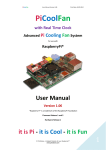
Auto-return time (from 1 to 60 minutes) is used to return the system to normal mode
(without camera exclusion) after a fixed time following selection by the Master
Operator. If set to 0 it is disabled and the system does not return to normal mode.
In the example the
Control Monitor sho
a cyclic sequence on
inputs 1, 2, 3 and 4
The Public Monitor
shows inputs 1 and 2
Camera 1 frames th
zone including the
Public Monitor.
During active contro
of video input 1 we
recommend removin
the input itself from
the cyclic sequence
the public monitor.
In this case it has be
replaced by input 5
called substitute
camera.
The camera is excluded only if the Public Monitors are in automatic cyclic
sequence. The Control Monitor is always number 1. The video input is excluded
when a camera is selected on the master monitor.
During exclusion the Control Monitor reads a warning message. This message is
overrided by an eventual alarm message.
To end camera exclusion press Seq to request the automatic sequence on the
Control Monitor.
Cameras ID Texts
The matrix allows up to 80 cameras to be connected. Each camera has an ID text of
max 28 char. When possible part of this text is shown in the various menus (when
defining the cyclic sequences for example) to make setup control easier. (Menu
3)
Page 20 of 33
MNYASM328S_0648
Move the cursor to the desidered camera by means of Inc and Dec . It is
possible to select quickly a camera text by pressing the number on the keyboard: i.e.
2 , 8 to select camera 28.
Enter is used to start modification of the ID text indicated by the cursor.
The text is inserted in the same way as for a cell phone: pressing a numeric key
quickly several times will run through the characters associated with the key; a
pause is used to pass to the next character.
Enter inserts a space and Clear erases the last character. Inc and Dec
change the character set.
Cyclic sequences
Cyclic sequences are series of cameras that are shown consecutively according to a
predefined order. (Menu 4.1)
Each sequence consists of max. 32 cameras, each of which can be shown for a time
ranging from 1 to 600 seconds. The cameras may be repeated within a sequence in
any order.
Defining and modifying the cyclic sequences
The definition screen shows the list of 32 available cyclic sequences. If a sequence
is empty (the cameras have not been defined) fixed camera 1 will be shown.
(Menu 4.2)
After choosing the sequence to define or modify press Enter to enter the edit
submenu.
Inside the edit submenu scroll through the 32 available steps with Inc / Dec and
request a change by pressing Enter : enter the time (from 1 to 600 seconds) and
the camera to be shown.
Times from 1 to 180 seconds are determined with 1-second step; from 181 to 400
seconds in 5-second steps; from 401 to 600 seconds in 10-second steps. Inserting a
time of 0 seconds or pressing Dec while changing a value erases the step.
Allocating cyclic sequences
After the cyclic sequences have been defined, the sequence to be shown must be
assigned to each monitor.
Press 1 (and 2 if Night Sequences are provided) to change the desired
sequence. The first cameras in the sequence are shown. (Menu 4.2)
Page 21 of 33
MNYASM328S_0648
Auto-return time
Auto-return time is the time between manual selection of a camera by the operator
and automatic return to the cyclic sequence (between 1 and 60 minutes). If set to 0 it
is disabled.
Alarms
Are alarms used?
Matrix alarms can be activated in 2 ways: (Menu 5)
z
z
Contact Alarms: the alarm is activated when the respective contact on the rear
connector is OPEN (if the alarm is defined as NORMALLY CLOSED) or
CLOSED (if the alarm is defined as NORMALLY OPEN)
Aux Command Alarms: the alarm is activated upon receving a proper
command from keyboard.
Functionally these 2 types of alarm behave in the same way and each alarm can be
either CONTACT or AUX COMMAND type but not both.
On alarm a number of automatic operations can be performed:
z
z
Switching of chosen cameras or sequences on some monitors (Menu 5.5)
Telemetry control to put connected domes/receivers on Home Position; up to 4
distinct positionings are available (Menu 5.6)
z
Close of relays (Menu 5.7)
z
Buzzer activation.
Contact Alarms
The matrix is supplied with 32 alarm contacts, which are defined as normally closed
or normally open.
Only alarm contacts on Single and Master Matrixes are available: contacts on Slave
matrixes are not enabled.
Alarm contacts that are not used should be set up as NOT USED to prevent false
signals in the event of disturbance.
An alarm is acknowledged if the corresponding actuating signal is at least 30ms
long.
Aux Command Alarms
The use of Aux Command Alarms allows flexible management of periferal units,
Page 22 of 33
MNYASM328S_0648
such as VCRs connected to the system and multiple actions by pressing a single
key.
AUX RESET commands are provided to reset the alarm condition by
keyboard. AUX COMMAND ALARMS can only be reset by keyboard.
Actions on telemetry receivers are also available when the dome/receiver is
controlled through a DVR (by Coax connection).
In this example it is assumed that:
z
z
z
on keyboard the Aux key sends to the matrix the message Aux+7 to activate
Alarm no.7
on the matrix Alarm no.7 is defined as AUX COMMAND and performs these
actions:
{
it closes relay 2
{
it switches a camera related to a DVR on a monitor
{
it moves dome no.17 to preset no.1 (home)
{
it enables the matrix buzzer
on the DVR, dome no.17 is connected through coax cable; it is also possible to
connect the domes even on the keyboard line.
This is the sequence of actions:
Page 23 of 33
MNYASM328S_0648
z
The operator (1) press the Aux key and a Aux+7 command is sent to the
matrix
z
The matrix (2) recognizes the command and set Alarm no.7 off
z
Relay no.2 is closed
z
The operator's monitor (6) shows an alarm-related camera
z
z
z
A message to move dome 17 to home is sent by the matrix
Alarm buzzer is activated
DVR (4) receives the command sent to the dome and retransmit it through
coax
z
Dome 17 (5) moves to home position
z
After closing the relay VCR (3) starts recording.
To reset the Alarm a command Aux-7 must be provided on the keyboard.
ID text
The Alarm ID Text can have a max. 28 characters and the procedure to define it is
the same for ID texts for the cameras. (Menu 5.2)
Reset modes
Each alarm can be silenced in various ways and the reset mode setting for one alarm
will not influence the other alarms. If more than one reset mode is defined for the
same alarm, this alarm will be silenced by recognition of the first reset from among
the definitions. (Menu 5.3)
For Contact Alarms four reset modes are available:
z
Continuous type reset: when the alarm signal ceases (instructed by a control
centre for example) the alarm event is silenced
z
Keyboard reset: keyboards able to reset the alarm are indicated
z
External reset: the alarm is silenced by an external reset trigger
z
Time reset : the alarm is automatically silenced following a specified time after
acknowledgement. This time can be selected from among 2, 5, 10, 20, 30, 60
seconds; 2, 5, 10, 15, 30, 60 minutes; 3, 6, 12 hours.
Notes
Do not use the continuous type reset if the alarm signal is of the pulsed type
Page 24 of 33
MNYASM328S_0648
(supplied by a sensor attached to a door for example)
The external reset trigger should be enabled to be able to reset the alarms by
external reset.
For Aux Command Alarms only a keyboard Aux Reset Command is available.
Enabling the alarm contact
Acknowledgement of alarm events can be limited to specific periods (day or night
period, always or never; the latter is useful if the alarm is to be temporarily disabled
without losing the already completed setting, such as when testing a
system). (Menu 5.4)
Effects on the monitors
When an alarm is acknowledged each video output may react differently: (Menu
5.5)
z
the alarm may be ignored
z
a fixed camera may be shown
z
a pre-defined cyclic sequence may be shown.
To change the effect on a monitor press the corresponding number; then
press 0 to ignore the alarm, 1 to request a cyclic sequence, 2 to request
a fixed camera.
If a sequence or a camera is requested it is then necessary to indicate the desired
number and then confirm it with Enter . A sequence/camera number equal to 0 or
pressing Dec during insertion will cancel the action.
Action on receivers
If the telemetry receivers are controlled via the matrix it is possible to reposition up
to 4 receivers when an alarm event is identified. (Menu 5.6)
The receiver number is always between 1 and 127. Setting the number 0 or pressing
Dec during insertion will cancel the action.
The action on alarm can be selected:
z
scan on predefined preset position
z
autopan
z
tour
Page 25 of 33
MNYASM328S_0648
z
sequence patrol.
Action on relays
If a relay is controlled by an alarm, acknowledgement of the alarm is able to close it
automatically. When more than one alarm controls the same relay,
acknowledgement of any one of these alarms will cause the relay to close. When all
alarms controlling the relay cease, the relay will open. (Menu 5.7)
Buzzer
It is possible to enable a warning buzzer on the matrix (each keyboard is set up
individually for another warning buzzer in the event of an alarm).
Image Masking
Image Masking is a system to hide part of the image when this comes from fixed
cameras. Do not mask signals from pan & tilt cameras, domes or VCR outputs: the
view provided by these devices changes continuously and cannot be effectively
masked. (Menu 6)
Masking may only be defined for video inputs present at the time of setup: in order
to be able to modify masking, the video signals should already be connected to the
matrix.
Changing the masking
If Enabled is OFF all Masks are not visible, even if previously defined.
Definition of a mask
Each camera is provided of a unique mask definition. (Menu 6.2)
Select the camera to be masked pressing Inc / Dec .
To erase completely a mask on the camera press
0
0 (zero twice).
Move the cursor with keys Up / Down / Left / Right and toggle active cell
visibility by pressing Enter .
Press Seq when mask definition is complete.
Composite systems
The matrix can be cascaded to connect more than 32 video inputs:
z
2 matrixes (1 Master + 1 Slave): up to 48 inputs
Page 26 of 33
MNYASM328S_0648
z
3 matrixes (1 Master + 2 Slaves): up to 80 inputs
A Slave matrix is just an extension card: it provide neither relays nor alarm contacts.
Keyboard can only be connected to the Master matrix.
1 Matrix and 1 Slave
Video inputs:
z
Master matrix from 1 to 16
z
Slave matrix from 17 to 48. The Slave matrix must be set as Slave no.1.
Connection cable is described in Aux Line.
Slave's outputs are connected to Master's inputs according to this table:
Slave output Master input
1
17
2
18
Page 27 of 33
MNYASM328S_0648
3
19
4
20
5
21
6
22
7
23
8
24
1 Matrix and 2 Slaves
Video inputs:
z
z
z
Master matrix from 1 to 16
Slave matrix no.1 from 17 to 48
Slave matrix no.2 from 49 to 80.
Connection cable is described in Aux Line.
Slave's outputs are connected to Master's inputs according to this table:
Page 28 of 33
MNYASM328S_0648
Slave 1 output Master input
Slave 2 output Master input
1
17
1
25
2
18
2
26
3
19
3
27
4
20
4
28
5
21
5
29
6
22
6
30
7
23
7
31
8
24
8
32
Event log
The matrix supplies a series of information, via the RS232 channel, for recording
the succession of significant events occurring to the system. This log file is also
extremely useful for identifying the cause of faulty operation due to errors when
setting up the matrix.
The log can be sent either to a serial printer or to a Personal Computer, for
subsequent processing in the latter case.
Warning! Serial printers are usually provided with a reception buffer:
printing will only commence when the buffer is full. Before removing the paper from
the printer force the printer to print the outstanding buffer, following the
instructions given in the user's manual for the printer. Usually OFFLINE forcing
followed by page feed is sufficient to empty the buffer.
Each event has a corresponding message in code that is sent to the RS232 channel.
The message is preceded by an indication of the date and time and is followed by a
checksum character.
List of event messages
Message
PowerOn
Parameters
-
Page 29 of 33
Meaning
Matrix switched on
MNYASM328S_0648
PowerOff1
-
Matrix switched off
PeriodDay2
-
Start of Day Period
PeriodNight2
-
Start of Closed Period
Time+1
-
Start of summer time
(DST)
Time-1
-
End of summer time
(TST)
Setup
-
Start of matrix setup
EndSetup
-
End of matrix setup
AlarmXX
XX: alarm number
1/32
Acknowledgement of
alarm XX
KeybXAlarmReset
X: keyboard
number 1/8
Reset alarms from
keyboard No.
Aux+XX
XX: aux command
from keyboard
An alarm activation is
requested from keyboard
Aux-XX
XX: aux reset
command from
keyboard
An alarm reset is
requested from keyboard
AlarmXXIdleOn
XX: alarm number
1/32
Alarm active but
disabled
AlarmXXIdleOff
XX: alarm number
1/32
Alarm idle but disabled
AlarmExtReset
-
External alarm reset
AlarmXXTimeReset XX: alarm number
1/32
Time alarm No.XX
AlarmXXAutoReset XX: alarm number
1/32
Continuous
Video-XX
XX: camera
number 1/32
Page 30 of 33
Video loss, camera No.XX
MNYASM328S_0648
Video+XX
XX: camera
number 1/32
Signal return, video
No.XX
CfgReset
-
Restore settings
MicroReset
-
Re-run program
EnKeybX
X: keyboard
number 1/8
Time event: keyboard
No.X
DisKeybX
X: keyboard
number 1/8
Time event:
CloseRelayX
X: relay number
1/8
Time event: relay No.X
OpenRelayX
X: relay number
1/8
Time event: relay No.X
EnContactXX
XX: contact
number 1/32
Time event: alarm
contact XX
DisContactXX
XX: contact
number 1/32
Time event: alarm
DateChange
-
Start date modification
DateSet
-
End of date modification
TimeChange
-
Start time modification
TimeSet
-
End time modification
1) The time at which the matrix was switched off is shown the next time it is
switched on
2) After the message for the start of the day/night period there is a description of the
status of the keyboards, relays and alarm contacts:
Message
Parameters
Page 31 of 33
Meaning
MNYASM328S_0648
KeyboardsX1..X8 X1..X8:
keyboard status
RelaysX1..X8
X1..X8: relay
status
Status of the keyboards
+ keyboard enabled, keyboard disabled
Status of the relays
+ relay controlled by alarm
enabled, - relay disabled, 1 relay controlled by time
events enabled, 0 relay
disabled
Status of the alarm contacts
ContactsX1..X32 X1..X32:
contact status
+ contact enabled, - contact
disabled
Baud rate and data format
The baud rate is the one set by the Dip Switch for communications with the
keyboards.
Format is 8 bit, No parity, 1 stop bit.
Technical specifications
Power supply:
100 - 240 V~ 47/63 Hz
Consumption (max):
24 W
Video:
32 inputs - 75 Ohm 1 Vpp (PAL / NTSC)
8 outputs - 75 Ohm 1 Vpp (PAL / NTSC)
> 6 Mhz
Lower cut-off frequency (3dB):
9 Hz
Signal/noise ratio (S/N):
> 47 dB @ 5.5MHz
RS232 communication to PC:
max. 15m
RS485 communication to
keyboards:
max. 1200m
Page 32 of 33
MNYASM328S_0648
RS485 communication to Aux
devices
(Mux and telemetry receivers):
max. 1200m
Relay contacts:
50 V AC/DC 0.5 A max
Net weight (excluding p.s.):
Epoxypoliester powder painted metal
enclosure
3.2 kg
180 (L) x 430 (W) x 94 (H) mm (rack 19''
2HE)
Working temperature:
0 - 45°C
Compliance to:
EN55022 Class A, EN50130-4, EN60065,
FCC Part 15 Class A
Page 33 of 33
MNYASM328S_0648