1
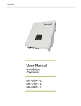
1 Version DC SOLAR DISTRIBUTION, INC. Solar Eclipse™ Mobile Solar Generators Technician Guide Solar Eclipse™ Mobile Solar Generators Technician Quick Guide DC SOLAR DISTRIBTION, Inc. 393 E. Channel Rd. Benicia, CA 94510 Phone 925.459.5615 Fax 925.798.3682 i The information described in this manual is distributed under license from DC SOLAR Distribution, Inc.. Your license agreement specifies the permitted and prohibited uses of this manual. Any unauthorized duplication or use of Solar Eclipse™ Mobile Solar Generators: Technician Quick Guide®, in whole or in part, in print, or in any other use prohibited. Every attempt has been made to make this document complete, accurate and up-to-date. Readers are cautioned, however, that DC SOLAR Distribution, Inc. is not responsible for damages caused by the reliance on the material presented in this manual, including, but not limited to, omissions, typographical errors, arithmetical errors or listing errors in the content material. DC SOLAR Distribution, Inc., reserves right to make changes to this manual without notice and shall not be responsible for updating the user with such changes or additions. The Solar Eclipse™ Mobile Solar Generators: Technician Quick Guide® is provided as courtesy “as is” without warranty of any kind, either expressed or implied. While the information in this manual has been carefully checked, DC SOLAR Distribution cannot be responsible for errors and reserves the right to change the specifications without notice. The use of any information found in this manual will be entirely at the user’s risk. This manual is Copyright © 2012, DC SOLAR Distribution, Inc. Solar Eclipse is a registered trademark DC SOLAR SOLUTIONS MFG., Inc. Inverter 5048U is a registered trademark of SMA America, LLC Midnite Solar Charge Controller charge controller a registered trademark of Midnite Solar MNPV3 & MNPV6 are registered trademarks of Midnite Solar Phono Solar is a trademark of Phono Solar Technology Co., Ltd. All other trademarks and registered trademarks are property of their respective holders. Manual version: 1.0 Corresponds to DC Solar Distribution version 1.0 February, 2012 Printed in the U.S.A. ii Warning: Electrical Hazard Authorized Personnel Only Use Caution When Using This Equipment Specifications iii by Model XC5 MODEL XC10 SCT20 22’’ L X 8’W X 7’6”H/ 22’’ L X 12’6”’W X 6’6”H 5,200 lbs Pintle 22'L X 8'W X 7'6"H/ 22'L X 12'6"W X 6'6"H GVWR Hitch 12'L X 9'W X 7'6"H/ 12'L X 11'W X 6'6"H 3,400 lbs Pintle Total Input (Watts) Movement 1,600W Manual 2,400W Manual 2,400W Manual Nominal AC voltage Nominal frequency Continuous AC output at 77 °F/ 113 °F(25 °C /45 °C) AC output power at 25°C (77°F) for 30 min/1min/3s Nominal AC current/ Max. Ac current (peak) THD output voltage/ power factor 120V 60Hz 5000w/ 4000w 120V 60Hz 5000w/ 4000w 120V 60Hz 5000w/ 4000w 6500W/8400W/ 11000W 41.7A/ 180A for for 60ms <3%/-1 to +1 6500W/8400W/ 11000W 41.7A/ 180A for for 60ms <3%/-1 to +1 13000W/16800W/ 22000W 41.7A/ 180A for for 60ms <3%/-1 to +1 Input voltage Input frequency Maximum AC input current 120V 60Hz 14A 120V 60Hz 14A ** ** ** Battery voltage Maximum battery charging current/ Continuous charging current Battery Type Battery Capacity 48V 48V 120A/100A 2x 48V 2x 120A/100A FLA 400 Ah DC 200 Ah AC FLA 510 Ah DC 205 Ah AC FLA 1,020 Ah DC 510 Ah AC Dimensions Transport/ Deployed 8,400 lbs Pintle PV Panels AC output AC Input Battery DC Input Non PV Charge 120V Male Battery remaining % 15/50/75 SB Connector Battery remaining % 15/50/75 14.9/ 8.8/ 4.4 hrs 4.5/2.7/1.3hrs Standard Features on All Models o o o o o o o o o o o o Ruggedly mobile with a polyurethane-coated steel frame Designed for on and off-road conditions Motion shock-absorbers for solar panel safety in movement Deep-cell industrial batteries with extended life and center-mounted for stability in transit Capable of being setup by a single adult and generating renewable energy in under 5 minutes No special permits or licenses required to operate or be towed in transit Flush mounted exterior outlets and breakers with backup generator and shore-power options Custom designed for rapid deployment and minimum maintenance Manufactured with high-efficiency polycrystalline solar modules Utilizes pure sine-wave outdoor rated inverters and equipment lockers 100% UL-Approved components with 10 year product warranty Designed and manufactured in the United States of America iv ™ Identify Equipment v Flow of Engery vi Table 1 Approximate Run time This is intended to serve as a guide to illustrate the approximate run time End Users may expect before complete depletion of the Battery (15%) occurs and recharging of the unit is required. The green cells indicate that, under the given parameters, the battery would never be drawn down, nor require external recharging. Other factors, such as array shading, lower rate of solar insolation, or inconsistent draw may affect performance and run time. The red cells indicate that, under the given parameters, the battery would require recharging before one “Work Day” was accomplished. Such a situation would require a Solar Eclipse that has been upgraded with a backup generator to recharge the battery. Full Sun (Hours) 5.5 5.5 5.5 5.5 5.5 5.5 5.5 5.5 5.5 5.5 5.5 5.5 5.5 5.5 5.5 5.5 5.5 5.5 5.5 5.5 5.5 5.5 vii Daytime Use (Hours) 8 8 8 8 8 8 12 12 12 12 12 12 8 8 8 8 8 8 12 12 12 12 Nighttime Use (Hours) 0 0 0 0 0 0 0 0 0 0 0 0 4 4 4 4 4 4 12 12 12 12 Average Draw (Amps) 15 20 30 40 50 60 15 20 30 40 50 60 15 20 30 40 50 60 15 20 30 40 Usable Work Days By Model XC10 STC20 2XSCT20 17.3 3.5 1.3 0.8 0.6 0.5 2.5 1.3 0.7 0.5 0.4 0.3 2.5 1.3 0.7 0.5 0.4 0.3 0.7 0.5 0.3 0.2 34.7 6.9 2.7 1.7 1.2 0.9 5.0 2.7 1.4 0.9 0.7 0.6 5.0 2.7 1.4 0.9 0.7 0.6 1.4 0.9 0.6 0.4 17.3 3.5 1.9 1.3 17.3 2.5 1.3 0.9 0.7 17.3 2.5 1.3 0.9 0.7 2.5 1.3 0.7 0.5 Table of Contents Identify Equipment ........................................................................ v Flow of Engery ..............................................................................vi Table 1 Approximate Run time ................................................... vii 1.1 Quick Starting the Solar Eclipse™ ............................. 11 2.1 Trailer ........................................................................... 14 Overview ...................................................................................... 14 Transporting ................................................................................ 14 Parking/ Positioning the Solar Eclipse™ .................................. 15 2.2 Positioning the PV Panels ........................................... 15 Deployment of PV Panels ........................................................... 15 2.3 Frequently Asked Questions ...................................... 17 3.1 Outlets .......................................................................... 19 Outlets.......................................................................................... 19 3.2 GFCI Circuits ................................................................ 19 GFCI Circuits ............................................................................... 19 Test Procedure ........................................................................... 20 Tripping the GFCI Circuit Modules ............................................ 20 3.3 Circuit Breaker ............................................................. 20 Circuit Breaker ............................................................................ 20 Tripping the Circuit Breaker ....................................................... 20 3.4 Frequently Asked Questions ...................................... 21 4.1 Overview....................................................................... 23 4.2 Display .......................................................................... 23 4.3 Menu Structure ............................................................ 26 4.4 Events, Warnings & Failures....................................... 27 Display of Events ........................................................................ 27 Display of Warning and Failures................................................ 27 Failure Confirmation ................................................................... 28 Display Code of Warning and Failures...................................... 28 Handling Pending Failures during the Booting Procedure ..... 30 4.5 Red & Green LEDs ....................................................... 31 Green LED ................................................................................... 31 Red LED ....................................................................................... 31 4.6 Keypad ......................................................................... 31 4.7 Breaker and SD Card ................................................... 32 Breaker......................................................................................... 32 DC Solar Distribution | PH 925.459.5615 8 Copyright 2012, All Rights Reserved SD Card ........................................................................................ 32 4.8 Non-PV Charge ........................................................... 32 2/O SB Industrial Connector ...................................................... 32 “Male” Plug.................................................................................. 32 4.9 Frequently Asked Questions ...................................... 33 5.1 Important Material Found in Job Box ......................... 36 Key ............................................................................................... 36 Registration ................................................................................. 36 Quick Start Instructions ............................................................. 36 5.2 Combiner/Breaker Box ................................................ 36 5.3 Charge Controller Overview........................................ 37 5.4 Frequently Asked Questions ...................................... 38 6.1 Battery .......................................................................... 40 Overview ...................................................................................... 40 6.2 Battery Metering on the Inverter ................................. 40 Accessing Meters........................................................................ 40 6.3 Battery Charge Stages and Meanings on the Charge Controller ........................................................................... 41 Bulk MPPT ................................................................................... 41 Absorb ......................................................................................... 41 Float ............................................................................................. 41 Equalize ....................................................................................... 41 6.4 Non-PV Battery Charge ............................................... 42 6.5 Frequently Asked Questions ...................................... 43 7.1 Maintenance of the Solar Eclipse™ ........................... 45 Trailer ........................................................................................... 45 PV Panels..................................................................................... 45 Spider Box ................................................................................... 45 Inverter ......................................................................................... 45 Job box ........................................................................................ 46 Battery.......................................................................................... 46 7.2 Frequently Asked Questions ...................................... 47 List of Figures ............................................................................. 48 List of Tables ............................................................................... 48 References................................................................................... 49 DC Solar Distribution | PH 925.459.5615 9 Copyright 2012, All Rights Reserved 1 Section General Operations: Quick Starting the Solar Eclipse™ DC Solar Distribution | PH 925.459.5615 1 0 Copyright 2012, All Rights Reserved 1.1 Quick Starting the Solar Eclipse™ Getting Started Park the Solar Eclipse™ in an open area free from shade, the hitch should point East and West for optimum performance. Deploying Solar Panels 1st - Identify the spring- locking “L” shaped pins at each end of the PV panels and pull out on the handle. 2nd - Rotate the PV panel to desired angle. ** Note, DC Solar recommends this is carried out by two adults. 3rd - Secure the PV panels after rotation by turning the spring-locking “L” shaped pins and locking it into place. Identifying the Equipment Standing at the Solar Eclipse™ ’s hitch; Spider Box with outlets (On trailer flatbed), Locked Job Box (Left side, can be identified by the key lock), the Inverter (Right side, has keypad with plastic covering), and the Battery (located on the rear of the trailer). Turning On At the outlet Spider Box, 1. Remove any equipment plugged into the outlets on Spider Box. At the Inverter 2. Lift plastic protective covering from bottom upwards to access breaker. 3. FLIP UP black breaker labeled “DC Disconnect”. 4. Wait until display reads: 5. Press and hold “ENTER” Hold until display bar descends: 6. Replace plastic protective covering. At the outlet Spider Box, 7. Verify both GREEN & RED LED lights are “on” next to each outlet. At the locked Job Box, 8. Unlock and open door. Identify the two different types of equipment found inside: Left - Gray Breaker box Right - Charge Controller (Black with LED screen) 9. On the left - Open Gray Breaker box from bottom upwards. DC Solar Distribution | PH 925.459.5615 1 1 Copyright 2012, All Rights Reserved 10. FLIP UP breakers 1-6. 11. On the right- Visually verify LED display on meter is now on. 12. Leave the door to the Job box OPEN for cooling while in use. You are now ready to plug your equipment into outlets on the Spider Box. Shutting Down At the outlet Spider Box, 1. Remove any equipment plugged into the outlets on Spider Box. At the locked Job box, (door should already be open for cooling). 2. On the left - Open Gray Breaker box from bottom upwards. 3. Next, FLIP DOWN breakers 1-6. 4. On the right- Visually verify LED display on Charge Controller is now off. 5. Close door to Job Box. At the Inverter, 6. Lift plastic protective covering from bottom upwards to access the breaker. 7. Press and hold “ENTER” Hold until display bar descends: 8. Inverter display reads: 9. Flip DOWN black breaker labeled “DC Disconnect”. 10. Wait a moment and verify display turns off. 11. Replace plastic protective covering. Cleaning and General Maintenance Keep panels free of dust and dirt for optimal usage. Use ONLY WATER, soft bristle brush, towel and squeegee for cleaning. NEVER USE any soaps or chemicals and NEVER power wash; this will DAMAGE the solar panels and will void the warranties. DC Solar Distribution | PH 925.459.5615 1 2 Copyright 2012, All Rights Reserved 2 Section Photovoltaic (PV) Solar Panels DC Solar Distribution | PH 925.459.5615 1 3 Copyright 2012, All Rights Reserved After this section you will: Recognize safety measures while transporting or shipping the Solar Eclipse™ Understand optimal Positioning of the Solar Eclipse™ Safely deploy the PV panels 2.1 Trailer Overview There are two rows of PV panels on the Solar Eclipse™. Each row consists of five panels. Transporting Anytime the Solar Eclipse™ is Figure 1 Vertical position of the PV towed or shipped, the PV panels for transporting. panels need to be in the upright/vertical position for safe transportation. Figure 1 When towing the Solar Eclipse™, o o First, secure the pintle/ ball hitch Then, attach the 7-way connector, the two safety chains, and brake cable to the main vehicle. Figure 2 Figure 2 Identifying equipment on hitch DC Solar Distribution | PH 925.459.5615 1 4 Copyright 2012, All Rights Reserved Parking/ Positioning the Solar Eclipse™ Park the Solar Eclipse™ in an open area, free from shade. Remember to park it in a location that has adequate clearance to deploy the panels. Anytime the Solar Eclipse™ is not in motion, place a block or wedge under the tires to prevent the Solar Eclipse™ from rolling. For the best results, point the Solar Eclipse’s™ hitch toward East or West. However, environmental constraints may require the hitch to be pointed South or North. Avoid any shading on the PV panels. 2.2 Positioning the PV Panels To safely deploy the PV panels, DC Solar Distribution recommends two adults deploy each row of panels; one near the hitch and the other at the rear. There are two “L” shaped, spring-loaded, pins per row of PV panels, and four in total on the Solar Eclipse™. Figure 3 Locate the “L” shaped spring-loaded, locking pin. The locking pins allow the PV panels to change positions. Figure 3 The four locations of the springThere is one position for loaded, locking pins transportation and storage; as there are three positions for deployment. Deployment of PV Panels Pull out on the “L” pins (on each end of the row of panels), adjust panel to desired angle, then turn “L” to lock panel into position on both sides of the PV DC Solar Distribution | PH 925.459.5615 1 5 Copyright 2012, All Rights Reserved panel. Figure 4. Repeat this for both of the PV rows of panels. Adjust the angle of the PV panels and confirm they are free from any shading. If shading is present, readjust panels until they are free of shade. Shade will decrease the PV arrays absorbed by the panels, thus reducing efficiency. In general, if the Solar Eclipse™ is parked with the hitch pointed East and West, the panels can be deployed flat. If no shading occurs, the panels are able to remain flat. However, if the Solar Eclipse’s™ hitch is pointed South and North, then adjustment of the PV panels may be necessary throughout the day. Watch your head!! Be aware of your surroundings. The PV panels hang low. The corners on PV Panels are marked with caution tape for your protection. Figure 4 explains how to adjust the angle of the PV panels DC Solar Distribution | PH 925.459.5615 1 6 Copyright 2012, All Rights Reserved 2.3 Frequently Asked Questions Q: Do I need to change the angle of my PV panels throughout the day? There are many factors that contribute to orientation of the PV Panels. As a general rule, be aware of any shading on the PV panels throughout the day and make any necessary adjustments. Optimal use of PV panels occurs when the Solar Eclipse’s™ hitch is pointed East or West. Therefore, adjustment of the PV panels may not be necessary. However, if the Solar Eclipse’s™ is pointed North and South, adjustment to the angle of the PV panels may be necessary to reach efficiency. Q: The PV Panels look dirty, are they still able to charge? Dust or dirt on the panels reduces the amount of solar arrays needed to produce electricity; therefore it is recommended that the panels are free of any surface dirt or dust. Q: Can I tow the Solar Eclipse™ with PV Panels deployed? No! Do not attempt to tow Solar Eclipse™ with panels deployed. Q: The PV panels are deployed, is my battery charging even though I haven’t turned any on the equipment No! The PV panels will only charge the battery when all breakers (1-6) on the Combiner/ Breaker box, (located in the Job Box) are all flipped up into the “ON” position. DC Solar Distribution | PH 925.459.5615 1 7 Copyright 2012, All Rights Reserved 3 Section Spider Box 1 1 (Construction Electrical Products) DC Solar Distribution | PH 925.459.5615 1 8 Copyright 2012, All Rights Reserved This section will inform you how to: Safely Use the Spider Box Understand Components Test Procedures 3.1 Outlets Outlets The Spider Box is equipped with different types of outlets. Table 2 Summarizes each model of Solar Eclipse™ and its available outlets. Outlets XC5 XC10 SCT20 20A Edison 6 6 6 20A Twist Lock - - - 30A Twist Lock 1 1 1 120/240 50-Amp Hubbell Twist 1 1 1 3.2 GFCI Circuits GFCI Circuits Each outlet on the spider box as a GFCI Circuit associated to it. Figure 5 GFCI Circuit modules are designed to protect against ground faults. However, they are not designed to protect against overloads or short circuits. The GFCI Circuit module does not eliminate the hazard of shock; however, it does limit the duration of the shock to a period that is considered safe for a normally healthy person. Use caution when in contact. Figure 5 GFCI Circuit Model on the left and the outlet on the right. DC Solar Distribution | PH 925.459.5615 1 9 Copyright 2012, All Rights Reserved Test Procedure There are two buttons associated with each GFCI Circuit module, labeled “test” and “reset”. The green LED light indicator is associated with the “test” and the red LED indicator is associated with the “reset”. Figure 6 Both red and green indicators must Figure 6 identifies the reset and test on the GFCI Circuit module. be visible to ensure safe use of the outlet. Every outlet on the Spider Box have both a “test” and “reset” with LED indicators on the Spider Box. Tripping the GFCI Circuit Modules If GFCI Circuit modules trips; First, attempt to reset it by following the test procedure. If after resetting a GFCI Circuit modules and it trips again immediately, the fault is still present. Unplug all equipment plugged into the Spider Box. Then, reset every GFCI Circuit Modules on the Spider Box. Reconnect the each plug into outlet one at a time; the GFCI Circuit module will trip when the faulted load is reconnected. 3.3 Circuit Breaker Circuit Breaker The circuit breaker is located on the rear of the Spider Box and is covered. Lift the cover to expose. Figure 7. The circuits should remain in the “on” Figure 7 Circuit Breaker and position. its cover Tripping the Circuit Breaker An overload or short circuit will cause the Circuit Breaker to trip. Once the fault is corrected or removed the circuit breaker can be reset by switching the breakers in the “OFF” position and then to the “ON” position. DC Solar Distribution | PH 925.459.5615 2 0 Copyright 2012, All Rights Reserved 3.4 Frequently Asked Questions Q: How do I verify power on the Spider Box? o o o o Check the GFCI buttons, and perform the test procedures if necessary. Verify that the Inverter is powered on. Check the breakers on the Spider Box (located on back of the Spider Box). Verify equipment you are attempting to power is functioning by testing it on another power source. Q: One outlet in the Spider Box doesn’t work. Check the GFCI reset buttons next to the outlet. Q: The Green LED is “ON” but the Red LED is “OFF” and the outlet is still working on the Spider Box, is it ok to continue use? STOP!! The RED LED is an indicator to identify when the outlet is GFCI protected. Therefore, if the GREEN LED is on but the RED LED is off the outlet is not protected. Continued use can result in injury. Contact DC Solar Distribution Immediately (925) 459-5615. Q: How do I reset a single outlet on the Spider Box? Press the Green “test” button, and then press the Red “reset” button. Q: I forgot to unplug my equipment from the outlets before shutting down the Inverter, is that a problem? This should not affect Inverter negatively, but it is recommended to remove your equipment before to shutting down the Inverter. Q: It is raining and I have my equipment plugged into the Spider Box, what do I do? The sockets are protected from water by the GFCI. Turn off equipment and following shut down procedures from the Quick Start Instructions found in Section 1 of this manual and also found in the Job Box on the Solar Eclipse™. Q: What’s the length of power cord can I use before losing current? It is not recommended to use a power cord longer than 250 feet. DC Solar Distribution | PH 925.459.5615 2 1 Copyright 2012, All Rights Reserved 4 Section Inverter 2 2 (SMA America, LLC, 2010) DC Solar Distribution | PH 925.459.5615 2 2 Copyright 2012, All Rights Reserved After this section you will understand: Safety and the Inverter Accessing the Menu and Submenus How to handle Errors and Failures Accessing an External Charge 4.1 Overview The Inverter pulls DC current from the Battery. Just as its name implies, the Inverter inverts DC into AC Current. This AC current is made accessible on the Spider Box. 4.2 Display The display has two lines, each with 16 characters. The top line is the menu number and the menu name, or the name of the parameter where applicable. The lower line has a series of symbols indicating the status of the Inverter. Figure 8 Figure 8 Display of the Inverter Table 3 Inverter’s display markers and descriptions. Marker Description A Output Pwr / Charging Pwr (load Status) B Direction of energy flow and system status C Displays if the Inverter parameters for grid operation or parameters for generator operation D Device assignment E Status of the external source (Asterisk, question mark or exclamation mark) F Relay 1 Status G Relay 2 status H Warning message (Exclamation Mark) DC Solar Distribution | PH 925.459.5615 2 3 Copyright 2012, All Rights Reserved Table 4 Inverter symbol meaning Symbol Meaning ] > Nominal power Nominal load exceeded. Direction of energy flow between grid/generator side, battery and load side. Generator/grid side is on. Battery Load side (loads/Sunny Boys) ╪ ╪ ╪× M1 * ? ! B C E L S Power pole The inverter is working with grid limits. The Inverter is working with generator limits. The Inverter is configured as master. Status of the external source: Voltage and frequency of the generator/grid are within set limits. Status of the external source: Voltage and frequency of the generator/grid are not within set limits. In this case, the Inverter does not connect the generator to the off-grid power system. Status of the external source is displayed (at position E): The maximum admissible generator reverse power was exceeded; the Inverter has disconnected the generator from the off-grid power system. Request reason “Battery”: The generator has been requested as a result of the battery charge level. Request reason”Cycle”: The generator was requested via the generator operation's time-dependent repetition cycle (parameter: 235.17 GnTmOpCyc). This symbol can only be shown in Multicluster operation. Request reason “External”: The generator was requested via the extension cluster. This request can only take place in multicluster operation. Request reason “Load”: The generator has been requested as a result of the load-dependent generator request. Request reason “Start”: The generator has been requested by the operator manually setting the generator request in the Inverter from “Auto” to ”Start”. The generator is then no longer automatically controlled or switched off by the Inverter. DC Solar Distribution | PH 925.459.5615 2 4 Copyright 2012, All Rights Reserved T ○● ! Request reason “Time”: The generator was started for one hour using the “Run1h” setting in the Inverter. Once this time has passed, the Inverter automatically switches off the generator. Display for relays (solid circle = the relay is activated / empty circle = the relay is deactivated). Warning message is displayed (at position (H): This symbol blinks until you have confirmed the warning or the error in the menu”#410 Failures Current” or ”#420 Failure History”. DC Solar Distribution | PH 925.459.5615 2 5 Copyright 2012, All Rights Reserved 4.3 Menu Structure Table 5 Outlines Inverter menu hierarchy DC Solar Distribution | PH 925.459.5615 2 6 Copyright 2012, All Rights Reserved 4.4 Events, Warnings & Failures In general, the Inverter distinguishes between events and errors. o o Events describe state changes or transient states (e.g. generator connection). Failures describe states that are not permitted or are only permitted up to a certain rate. This includes warnings, failures and errors. A user interaction is generally required. Display of Events The Inverter can display a list of events: The running count of the events is on the upper line; the date and time display changes in 2second intervals on the lower line are the number of the event and the corresponding short text. Figure 9 Figure 9 Display of events Display of Warning and Failures The Inverter can display a list of errors and warnings: The running number (quantity) of the errors is on the upper line; the time and date display changes in 2-second intervals. On the lower line is the number of the error and the corresponding error short text. A “!” on the right on the upper line indicates when Figure 10 Display of warning and the warning and/or error occurred. A “C” on the right on the upper line indicates when the failures warning or the error was confirmed or cleared. Figure 10 Direct Access to the Error List: As a shortcut, press ESC and the arrow up button simultaneously to go directly to the error list (#420 Failure History). DC Solar Distribution | PH 925.459.5615 2 7 Copyright 2012, All Rights Reserved Failure Confirmation If there is a disturbance or failure, the Inverter goes into standby. Proceed as follows to confirm a failure: 1. Remove the cause. 2. Confirm failure with <ENTER>. 3. Start the Inverter again. Display Code of Warning and Failures In the event of a failure, and provided it is recorded, “!” is displayed for a failure that has occurred and “C” is displayed for a failure that has stopped. Each failure and each event have a unique three-digit display number that is created according to the parameter/measuring value assignment. The events and failures have the identical numerical range: o o o o o o o o 1xx - INV – Inverter 2xx - BAT - Battery 3xx - EXT - Extern 4xx - GEN - Generator 5xx - GRD - Grid 6xx - RLY - Relay 7xx - SYS – System 8xx - AUX - external devices and components Table 6 Warning and Failures Codes; “F” marks a failure; “W” marks a warning Display Level F109 F113 F117 F121 W137 F141 F158 F201 F206 F208 W209 W210 W211 W212 W220 3 3 2 3 1 2 2 2 3 3 1 1 1 1 1 Description Transformer over temperature Over temperature on heat sink AC current limit (short-circuit control active for too long) Inverter overvoltage Derating due to temperature (heat sink or transformer Inverter under voltage Voltage on output AC1 Measuring range of battery voltage exceeded Battery over temperature Battery excess voltage Battery excess voltage Battery overvoltage warning Low battery temperature warning High battery temperature warning Warning SOH < 70 % DC Solar Distribution | PH 925.459.5615 2 8 Copyright 2012, All Rights Reserved W309 F314 W315 W319 W323 W327 W331 W335 1 2 1 1 1 1 1 1 W339 W343 1 1 W347 W351 W401 W501 F605 F702 F703 F704 W705 F706 1 1 1 1 4 5 2 4 1 4 F710 W713 F716 F720 F721 W722 W723 F731 F732 W738 F739 F743 W753 F754 W755 W756 W757 W758 W782 F801 W804 W805 F806 W807 W808 4 1 2 4 4 1 1 4 4 1 3 3 1 2 1 1 1 1 4 4 1 1 4 1 1 Relay Protection External voltage failure Grid/generator disconnection due to insufficient external voltage Grid/generator disconnection due to excessive external voltage Grid/generator disconnection due to insufficient external frequency Grid/generator disconnection due to excessive external frequency Grid/generator disconnection due to anti-islanding Disconnection from grid/generator due to violation of voltage limits (redundant measurement) Grid/generator disconnection due to voltage rise protection Disconnection from the external source, because the elation of the external voltage to the battery voltage is too high. Disconnection from external source due to excessive load Disconnection from external source due to external short-circuit Reverse power protection (generator) Grid reverse current prohibited (quick grid disconnection) Transfer relay does not open DSP reset Timeout during a task Invalid DSP calibration DSP watchdog has been triggered Watchdog meter has expired (watchdog triggered several times in succession) Auto-start meter has expired (several auto -starts in succession) Watchdog has been triggered Measuring range of battery voltage exceeded Short-circuit or cable break on transformer temperature sensor Short-circuit or cable break on heat sink temperature sensor Short-circuit battery temperature sensor Cable break on battery temperature sensor Error in the cluster configuration Error in the address assignation of the cluster devices Synchronization not successful Internal communication of the master is interrupted Internal CAN communication of the master is interrupted Invalid system time Communication with Multicluster Box interrupted Battery Preservation Mode 1 (LBM) Battery Preservation Mode 2 (LBM) Battery Preservation Mode 3 (LBM) No output voltage measured from the main cluster Failure of the grid monitoring 4 Plausibility check of the contactors in a Multicluster Box has failed Grid operation not possible Generator operation not possible Multicluster Box settings do not correspond to the software settings. No valid grid voltage with the requested grid operation Fault in contactor Q4 DC Solar Distribution | PH 925.459.5615 2 9 Copyright 2012, All Rights Reserved F809 F810 F811 W815 F816 F818 W851 W852 W853 W854 W855 W856 W857 W861 4 4 4 1 2 4 1 1 1 1 1 1 1 1 W862 W863 W864 W865 W867 W871 1 1 1 1 1 1 W872 W873 W874 W875 W876 W877 W881 1 1 1 1 1 1 1 W882 W883 W884 W885 W886 W887 F890 1 1 1 1 1 1 2 Fault in contactor Q10 (load shedding) Error in 15 V supply of the Multicluster Box Error in 24 V supply of the Multicluster Box Fault in contactor Q5 Fault in contactor Q7 A phase is missing, Multicluster Box goes into ”Failure” status Pole of battery connection is reversed or short-circuit on the Sunny Battery overvoltage Inverter Charger Overvoltage PV generator Inverter Charger No PV voltage or short-circuit on Inverter Charger 1 Sensor error (or under temperature) on Inverter Charger 1 Over temperature Inverter Charger 1 No communication with Inverter Charger 1 for more than 24 h Pole of battery connection is reversed or short-circuit on the Inverter Charger 2 Battery overvoltage Inverter Charger 2 Overvoltage PV generator Inverter Charger 2 No PV voltage or short-circuit on Inverter Charger 2 1 Sensor error (or under temperature) on Inverter Charger 2 No communication with Inverter Charger 2 for more than 24 h Pole of battery connection is reversed or short-circuit on the Inverter Charger 3 Battery overvoltage Inverter Charger 3 Overvoltage PV generator Inverter Charger 3 No PV voltage or short-circuit on Inverter Charger 3 Sensor error (or under temperature) on Inverter Charger 3 Over temperature Inverter Charger 3 No communication with Inverter Charger 3 for more than 24 Pole of battery connection is reversed or short-circuit on the Inverter Charger 4 Battery overvoltage Inverter Charger 4 Overvoltage PV generator Inverter Charger 4 No PV voltage or short-circuit on Inverter Charger Sensor error (or under temperature) on Inverter Charger Over temperature Inverter Charger 4 No communication with Inverter Charger 4 for more than 24 h Fault at the external measuring point of the Multicluster Box Handling Pending Failures during the Booting Procedure During the booting procedure, all pending failures are generally confirmed without an entry being made in the history. This way, after the booting procedure failure that is still pending will be re-entered, or if the system detects that this failure has stopped, it is entered as no longer being present. DC Solar Distribution | PH 925.459.5615 3 0 Copyright 2012, All Rights Reserved 4.5 Red & Green LEDs Green LED The GREEN LED indicates the inverter is in operation or standby. Figure 11 Red LED The RED LED indicates a disturbance or fault. Both the RED and Figure 11 Indentifying LEDs and Keypad GREEN LEDs light simultaneously during initialization. 4.6 Keypad The keypad allows the user to access the menus and submenus on the Inverter. Figure 11 ENTE R ESC Use “Enter” as Confirmation or yes, navigate one menu level down and to START and STOP device (when held down). Use “ESC” to cancel a function, answer no, or to navigate one menu level higher. Use the arrow keys to navigate through the menus. The Inverter display will go into sleep mode after a short time of no action being taken on the screen. The display will turn off. Simply press the any key to wake the display. DC Solar Distribution | PH 925.459.5615 3 1 Copyright 2012, All Rights Reserved 4.7 Breaker and SD Card Breaker The breaker is located on the front of the Inverter, Labeled “DC Disconnect”. The breaker is the main on/ off switch for the Inverter. Figure 12 When flipped up in the “ON” position, the Inverter is connected to DC power. SD Card The SD card is found to the right of the breaker. It serves as two critical functions for the Inverter; it maintains parameters designed specifically for the Solar Eclipse and it archives crucial data. Figure 12 Figure 12 Breaker and SD card The SB card saves all disruptions, allowing technicians to monitor problems with the unit. Therefore, the SD CARD should never be removed unless authorized by DC Solar Distribution. 4.8 Non-PV Charge 2/O SB Industrial Connector3 The SB Industrial Connector is located under the front, right side of the inverter. It is a 350 amp, 600 volts. This industrial connector is used for supplemental or addition battery charge. Figure 13 “Male” Plug Figure 13 Non-PV charge 3 The “Male” Edison plug is located under the front, right side of the Inverter, next to the SB Industrial Connector. The 120 v, 15 Amp “Male” Wall Plug enables the Inverter to plug into any standard Edison “Female” outlet. Figure 13 (Anderson Power Products®) DC Solar Distribution | PH 925.459.5615 3 2 Copyright 2012, All Rights Reserved 4.9 Frequently Asked Questions Q: Can I remove the SD card? Never, remove SD card. Removal of SD could harm the integrity of device. Only qualified technicians are allowed to remove. Q: The SD card has been removed and is missing, what do I do? Contact DC Solar Distribution Immediately (925) 459-5615. Q: What if I flipped down the breaker but forgot to Press and Hold “Enter”? (step #7 on the Shutting Down on the Quick Start Guide) This is a safety measure for the device, always power down properly before shutting off the Inverter’s breaker. Q: The Inverter screen is blank, what do I do? o o o o Check breaker to verity it is flipped upward in the “on” position. Press Enter on the Keypad, The display goes into sleep mode. Verify that battery is plugged in the Inverter. If the battery may have dropped below 15%. Shut off breaker on inverter by flipping down. Then wait 15 minutes and retry powering on procedures (You may need to do this twice). Q: The Inverter screen asked me for a password, what’s the password for the inverter? Password protected portions of the Inverter are for DC Solar Distribution technicians use only. Contact DC Solar Distribution for assistance (925) 459-5615. Q: The display has a flashing exclamation point (!), what does this mean? An error or warning has occurred. Q: How do I find the error code? Go to menu #400 Events (hit “enter”), then to #410 failures current, (hit “enter”) this will display current error DC Solar Distribution | PH 925.459.5615 3 3 Copyright 2012, All Rights Reserved Q: How do I know how much power I am drawing? From the home screen, down arrow to #100 meter (hit “enter”) then arrow down to 150# Compact meters Q: Can I need to plug this system into a wall socket? A 15 amp “Male” plug can be found on the front of the inverter. The Inverter should be turned on before plugging into wall socket. DC Solar Distribution | PH 925.459.5615 3 4 Copyright 2012, All Rights Reserved 5 Section Job Box DC Solar Distribution | PH 925.459.5615 3 5 Copyright 2012, All Rights Reserved After this section you will: Know where important paperwork can be found Identify equipment found in the Job Box Be able to read and understand the display on the Charge Controller 5.1 Important Material Found in Job Box Key The key locks the Job Box and protects all of its contents; do not lock the Job Box when the Solar Eclipse™ is in use. Leave the Job Box door open for ventilation. Registration A laminated copy of the registration can be found in the Job Box. The Department of Motor Vehicles (DMV) requires that all vehicles carry its registration on board. The registration identifies the vehicle identification number (VIN) and the license plate number. Quick Start Instructions Also found in the Job Box are the Basic operating instructions of the Solar Eclipse™ (Also found in Ch1). 5.2 Combiner/Breaker Box4 The Combiner/ Breaker Box is located on the upper left side of the Job Box. Inside are 6 breakers: o Breakers 1-2 manage the left row of PV panels. o Breakers 3-4 manage the right row of PV panels. o Breakers 5-6 power the Charge Controller. The breaker box will have a main power switch on the front of the breaker box as in figure 14. The power should be manage from the large red switch on front of the box. Figure 14 4 (MidNite Solar Inc., 2010) DC Solar Distribution | PH 925.459.5615 3 6 Copyright 2012, All Rights Reserved However, in some cases the breaker box may not have the main power switch located on the front. If this is the case then the breakers will need to be turned on individually. To expose the breakers: o Lift up on the cover from the bottom. The cover is able to be held open on its own. Figure 15 The breaker box found in the job has Figure 14 to be in on position (flipped up) Combiner/ Breaker when the Solar Eclipse™ is in use. box with single power switch Figure 15 Combiner/ Breaker box, accessing breakers 5.3 Charge Controller Overview The Charge controller doesn’t require any programming. It is delivered already configured for optimal use. Figure 16 The Charge Controller blocks reverse current and to protect the battery from overcharge, which in turn, lengthens the life of the battery. Figure 16 Charge Controller DC Solar Distribution | PH 925.459.5615 3 7 Copyright 2012, All Rights Reserved 5.4 Frequently Asked Questions Q: Why do I need to leave the door open? The door to the job box must be left open during operation to prevent the Charge Controller from overheating. Q: Some rain got in the Job Box, what should I do? Make sure the drainage hole at the bottom of job box is free of debris to allow drainage. Q: I lost the key, what do I do? Contact DC Solar Distribution for a replacement: (925) 459-5615 Q: I lost the registration, what do I do? Contact DC Solar Distribution for a replacement: (925) 459-5615 Q: I lost the Quick Start Instructions and now I don’t know how to turn it on. Section 1 of this manual has the Quick Start Instructions. You can also contact DC Solar Distribution for replacement: (925) 459-5615 Q: How do I adjust the charge controller? Do not make adjustments to the Charge Controller. They are delivered to the customer preset. Any adjustments could cause malfunctions of the equipment. Q: Do all six breakers need to be in the “ON” position? Yes. DC Solar Distribution | PH 925.459.5615 3 8 Copyright 2012, All Rights Reserved 6 Section Battery DC Solar Distribution | PH 925.459.5615 3 9 Copyright 2012, All Rights Reserved After this section you will: Be able to identify the battery Understand the battery status on the Inverter and Charge Controller 6.1 Battery Overview The 48v Flood Lead Acid (FLA) battery5 is located towards the rear of the Solar Eclipse™. Depending on the model, the Solar Eclipse™ can be equipped with one or two batteries. Figure 17 Figure 17 Single Battery and Double Battery 6.2 Battery Metering on the Inverter6 Accessing Meters From the home screen, down arrow to #100 meter (hit “enter”) then arrow down to 150# Compact meters A. Meter name B. % of Battery C. % Error accuracy D. Current of charge or discharge E. Temperature of Battery Figure 18 Accessing battery meter on Inverter 5 (Hawker, 2012) 6 (SMA America, LLC, 2010) DC Solar Distribution | PH 925.459.5615 4 0 Copyright 2012, All Rights Reserved 6.3 Battery Charge Stages and Meanings on the Charge Controller7 Bulk MPPT This stage of the Charge Controller means; that the Charge Controller will be putting out as much current as it can trying to charge the batteries to the absorb voltage set point. This is also known as constant current mode. Absorb This stage means that the Charge Controller will maintain the absorb set point voltage until the batteries are charged or it reach Float stage. At this stage the Charge Controller is not putting out maximum current, as that would increase the battery voltage over the Absorb set point. This is also referred to as constant voltage mode. The absorb time is proportional to the bulk time. (i.e. the time bulk takes to reach the absorb voltage.) The battery it‘s considered ―full at the end of the absorb charge cycle. Float A Float cycle follows after the Absorb cycle is completed; Float is displayed on the screen. Battery voltage is held at the float voltage set point, float time can be changed by the user. Equalize Equalization function has to be enabled by the user, refer to page 25. The intent of an equalization charge is to bring all battery cells to an equal voltage by a deliberate overcharge. The goal is to return each battery cell to its optimum condition through a series of voltage controlled chemical reactions inside the batteries. The main function of a charge controller or regulator is to protect your battery from overcharge and block a reverse current. If a non-self-regulating solar array is connected to lead acid batteries with no overcharge protection, the life of your batteries will be compromised. 7 (MidNite Solar Inc., 2010) DC Solar Distribution | PH 925.459.5615 4 1 Copyright 2012, All Rights Reserved Simple controllers contain a transistor that shunt the PV charging circuit, terminating the charge at a pre-set high voltage and, once a pre-set reconnect is reached, opens the shunt, allowing charging to resume. 6.4 Non-PV Battery Charge At the battery can be charged from additional sourcesAs mentioned in section 4.8, the battery can be charged by the SB Industrial Connector and the Male Wall Connector. To use an external (non PV) charge, the Inverter breaker needs to be in the “ON” position and the display must be in the standby mode. Table 7 The battery life remaining at 15%, 50% and 75% and the amount of time it takes using each external charge method. Battery life Remaining Time to % in hrs SB Male wall plug 15% 4.5 14.9 50% 2.7 8.8 75% 1.3 4.4 DC Solar Distribution | PH 925.459.5615 4 2 Copyright 2012, All Rights Reserved 6.5 Frequently Asked Questions Q: How do I know how much battery power I have left? From the home screen on the Inverter, down arrow to #100 meter (hit “enter”) then arrow down to 150# Compact meters A. Meter name B. % of Battery C. % Error accuracy D. Current of charge or discharge E. Temperature of Battery Q: Do the Inverter and the Charge Controller monitor the same battery characteristics? No, the Charge Controller monitors voltage while the Inverter monitors amps. However, the Inverter is plugged into a non-PV source it will monitor volts. Q: What is the most efficient non-PV charge? The SB industrial Connector is the most efficient. DC Solar Distribution | PH 925.459.5615 4 3 Copyright 2012, All Rights Reserved 7 Section Maintenance DC Solar Distribution | PH 925.459.5615 4 4 Copyright 2012, All Rights Reserved After this section will: Know the responsibilities required to maintain the Solar Eclipse™. 7.1 Maintenance of the Solar Eclipse™ The Solar Eclipse requires relatively low maintenance; however there are a few simple maintenance procedures that will ensure the longevity of the Solar Eclipse™. Trailer The “L” shaped locking pins need lubrication o Use super white multi-purpose grease, Tires o Maintain a tire pressure of 65psi. PV Panels Keep panels free of dust and dirt for optimal use. o Clean with ONLY WATER, soft bristle brush, towel and squeegee for cleaning. NEVER USE any soaps or chemicals and NEVER power wash; this will DAMAGE the solar panels and will void the warranties. Spider Box There isn’t any routine maintenance for the Spider Box. However, it is important to be aware of the status of the GFCI light indicators. See Section 3 for Spider Box. Inverter Firmware update o DC Solar Distribution will contact the user when updates are needed. Plastic cover o If there are any rips or cracks on the plastic cover, contact DC Solar immediately for replacement (925) 459-5615 DC Solar Distribution | PH 925.459.5615 4 5 Copyright 2012, All Rights Reserved Job box Ventilation o The Job Box must remain open while in operation for ventilation. Water drainage o In the bottom of Job Box, keep the drainage hole clear. Battery8 There are 24 water reservoirs on each battery. After a full charge: o Each of reservoirs should be filled with distilled water 1/4 inch over the battery plate. Figure 19 & Figure 20 Figure 20 Automatic shut-off battery filler 8 Figure 19 Battery reservoir plate (Hawker, 2012) DC Solar Distribution | PH 925.459.5615 4 6 Copyright 2012, All Rights Reserved 7.2 Frequently Asked Questions Q: Can I power wash the PV Panels on low and be really careful? No! Power washing of any kind is not allowed and will void any warranties. NEVER POWER WASH, Q: What kind of cleaning products can I use to clean the PV panels? Never use any kind of chemical or soaps on PV Panels. Use Water only. Q: The PV panels still look dirty after I washed them with water, what can I do to clean them better? Rewash the PV panels with water using only towels, soft bristle brushes or squeegees, never power wash. DC Solar Distribution | PH 925.459.5615 4 7 Copyright 2012, All Rights Reserved List of Figures Figure 1 Identifying equipment on hitch ............................................................................................ 14 Figure 2 Vertical position of the PV panels for transporting. ...................................................... 14 Figure 3 The four locations of the spring- loaded, locking pins ................................................ 15 Figure 4 explains how to adjust the angle of the PV panels ....................................................... 16 Figure 5 GFCI Circuit Model on the left and the outlet on the right. ....................................... 19 Figure 6 identifies the reset and test on the GFCI Circuit module. ........................................... 20 Figure 7 Circuit Breaker and its cover .................................................................................................. 20 Figure 8 Display of the Inverter .............................................................................................................. 23 Figure 9 Display of events......................................................................................................................... 27 Figure 10 Display of warning and failures .......................................................................................... 27 Figure 11 Indentifying LEDs and Keypad ............................................................................................ 31 Figure 12 Breaker and SD card ............................................................................................................... 32 Figure 13 Non-PV charge ......................................................................................................................... 32 Figure 14 Combiner/ Breaker box with single power switch....................................................... 37 Figure 15 Combiner/ Breaker box, accessing breakers ................................................................. 37 Figure 16 Charge Controller .................................................................................................................... 37 Figure 17 Single Battery and Double Battery .................................................................................... 40 Figure 18 Accessing battery meter on Inverter ............................................................................... 40 Figure 20 Battery reservoir plate ............................................................................................................ 46 Figure 19 Automatic shut-off battery filler ......................................................................................... 46 List of Tables Table 1 Approximate Run time............................................................................................................. vii Table 2 Summarizes each model of Solar Eclipse™ and its available outlets........................ 19 Table 3 Inverter’s display markers and descriptions. ...................................................................... 23 Table 4 Inverter symbol meaning .......................................................................................................... 24 Table 5 Outlines Inverter menu hierarchy........................................................................................... 26 Table 6 Warning and Failures Codes; “F” marks a failure; “W” marks a warning ................. 28 Table 7 The battery life remaining at 15%, 50% and 75% ............................................................ 42 DC Solar Distribution | PH 925.459.5615 4 8 Copyright 2012, All Rights Reserved References Anderson Power Products®. (n.d.). SB® Connector Family. SB® Connector Family . Sterling, MA. Construction Electrical Products. (n.d.). CEP 6506GU, 6506G. CEP 6506GU, 6506G; Temporary branch power distribution unit . Hawker. (2012). Flood Lead Acid Battery. Ooltewah, TN. MidNite Solar Inc. (2010). MidNite Solar's Classic charge controller User’s Manual. MidNite Solar's Classic charge controller User’s Manual . SMA America, LLC. (2010). The Sunny Island 5048U. The Sunny Island 5048U Off-Grid Inverter . Denver, Co. DC Solar Distribution | PH 925.459.5615 4 9 Copyright 2012, All Rights Reserved