1
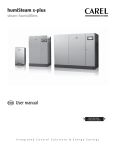
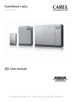
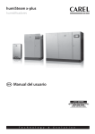
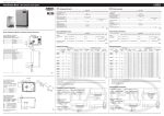
EN
4. ELECTRICAL CONNECTIONS
outside unit, bottom view
inside unit, top view
Check that the power supply voltage of the appliance corresponds to
the value indicated on the rating plate inside the electrical panel. Insert
the power and ground connection cables into the electrical panel
compartment using the tear-proof cable gland supplied, or through the
cable gland with cable stop, and connect the ends to the terminals (see
Fig. 4.c). The humidifier power line must be fitted, by the installer,
with a disconnecting switch and fuses protecting against short circuits.
Table 13.a lists the recommended cross-sections of the power supply
cable and the recommended fuse ratings; note, however, that this data
is purely a guide and, in the event of non-compliance with local
standards, the latter must prevail.
1
2
3
3
2
1
Note: to avoid unwanted interference, the power cables should
be kept apart from the probe signal cables.
Single-phase models
am
iSte
hum
am
iSte
hum
GND
Models UE025 to UE130
outside unit, side view
Three-phase models
GND
Fig. 4.a
user
Before making the connections, ensure that the machine is
disconnected from the mains power supply.
Models UE001 to UE018
installer
4.2 Power cable connection
4.1 Preparing the electric cableways
L N
L1 L2 L3 N
service
1
Fig. 4.c (view inside unit, electrical compartment)
1
3
2
Important: connect the yellow-green cable to the earth point
(GND).
(1) In the 400 V three-phase models, also connect the neutral (N)
Fig. 4.b
4.3 Control signals ( M2.1 - M2.8; M7.1 - M7.2)
Key to Figs. 4.a & 4.b:
1.
2.
3.
power cable inlet;
optional utility cable inlet (after drilling).
probe cable inlet. On models UE001 to UE018, remove the plastic “tab”
and use it to secure the cable (held in place by the screws provided).
Steam production by the humidifier is enabled or controlled.
For connection of control signals, use the connection kit (supplied in the
packaging) and run the cables from the humidifier through the cable
gland (Fig. 4.a or 4.b).
Depending on the type of signal used, steam production can be enabled
and/or managed in different ways.
1. Enable steam production using:
REMOTE CONTACT (ON/OFF action)
• jumper outputs M7.1 and M7.2
• connect outputs M2.7 and M2.8 to a remote contact (e.g.: switch,
timer,…)
M.2
M.7
M.2.1 M.2.2 M.2.3 M2.4 M.2.5 M.2.6 M.2.7 M.2.8
M.8
M.7.1 M.7.2
Fig. 4.d
15
“UEX-PLUS” +030220621 - rel. 1.4 - 04.08.2009