1
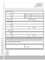
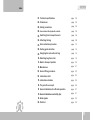
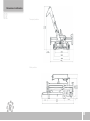
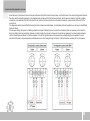
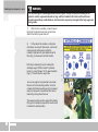
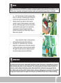
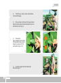
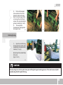
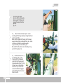
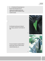
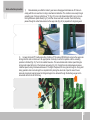
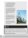
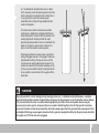
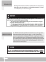
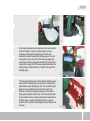
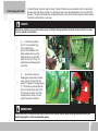
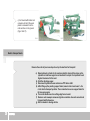
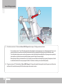
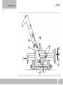
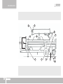
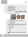
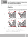
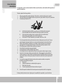
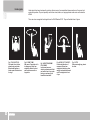
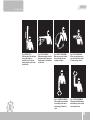
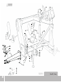
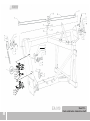
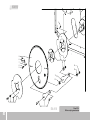
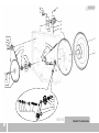
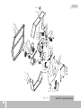
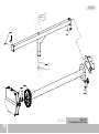
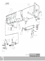
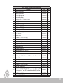
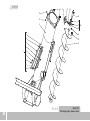
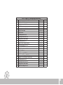
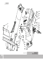
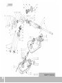
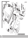
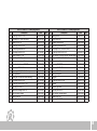
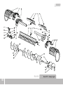
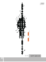
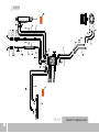
RICHIGER
EA 910 UNLOADER
CDDF00051A
Operator's Manual
Parts list
EA 910 UNLOADER
Operator's Manual
This manual
Richiger has endeavored to provide the most accurate and clear information on this equipment.
Because of efforts to produce the best equipment possible, upgrades and improvements may
precede this or subsequent manuals' updates. Therefore, contents of this manual are based on
development in effect at the time of publication and are subject to change without notice.
Important
Before attempting machine operation, read this manual's instructions carefully.
This manual contains information and recommendations that may vary in accordance with user
experience, climate, grain type, tractor weight and other variable conditions.
CDDF00051A
Warranty policy
Warranty terms
Limitations on Warranty
Unit: Hydraulic-Mechanical Grain Bag Unloader
Model: EA-910
RICHIGER MAQUINARIAS S.A, located in Avellaneda 661, Sunchales, Santa Fe province, Argentina, warrants its
product EA-910 mechanical grain unloader from defects in materials and workmanship under normal operating
conditions and proper application, in accordance with the specifications for operation as described by the
manufacturer, for the period of 365 days from date of delivery to buyer.
This warranty is expressly in lieu of any other warranties, express or implied, including any warranty of merchantability
or fitness for a particular purpose.
Buyer's sole and exclusive remedy under this warranty shall be limited to the repair, replacement or exchange of
warranted parts at our option, F.O.B. our factory, or designated service center, agent or representative. If the agent or
representative grants any warranty greater in scope or time period or labor allowance than that detailed herein,
RICHIGER MAQUINARIAS S.A shall not be liable beyond the herein stated limitations.
Equipment and accessories not of our manufacture are not covered by this warranty. Any claim with regards to
defective aforementioned equipment and accessories shall be submitted by RICHIGER MAQUINARIAS S.A to the
original manufacturers for analysis and subsequent non-approval or approval of repair, replacement or exchange, at
their option.
No special, incidental, consequential or other damages or contingent liabilities including, but not limited to, loss of life,
personal injury, loss of crops, loss due to fire or water damage, loss of business or business income, down time costs
and trade or other commercial loss arising out of the failure of product. The term product and products as used in this
warranty designates the whole finished unit in its entirety, i.e. the complete assembled machine, and/or all and every
individual component, part, equipment and accessory that forms said complete assembled machine.
Normal wear and tear associated with use is expressly excluded from this warranty.
No products shall be returned without prior authorization from RICHIGER MAQUINARIAS S.A.
Buyers and their agents shall prepay all transportation charges for the return of such products to RICHIGER
MAQUINARIAS S.A. or designated service center. There will be no acceptance of any charges for labor and/or parts
incidental to the removal and remounting of product repaired or replaced under this warranty.
This warranty does not cover conditions over which RICHIGER MAQUINARIAS S.A. has no control including, without
limitation, contamination, pressures in excess of the recommended maximum, products damaged or subject to
accident, abuse or misuse after shipment from factory, products altered and repaired by anyone other than RICHIGER
MAQUINARIAS S.A. factory personnel or representative or source approved by RICHIGER MAQUINARIAS S.A in
writing prior to commencement of said work.
The first buyer is responsible for proof of delivery date of product for the purpose of establishing warranty time of
validity. Warranty can continue for new user should the product be resold by the first buyer during valid period of
warranty, only if this situation is reported in writing, with enclosed documentation as proof of purchase. Warranty will
not be applicable if series number or other identification markers are erased, obliterated or otherwise altered.
Limitations on Warranty
The first buyer is responsible for proof of delivery date of product for the purpose of establishing warranty time of
validity. Warranty can continue for new user should the product be resold by the first buyer during valid period of
warranty, only if this situation is reported in writing, with enclosed documentation as proof of purchase. Warranty will
not be applicable if series number or other identification markers are erased, obliterated or otherwise altered.
The following are types of failures which are not attributable to defects in materials and/or workmanship and which
are not considered by RICHIGER MAQUINARIAS S.A. as part of the warranty extended hereunder. This listing is by
way of example and is not intended to be exhaustive:
1)
2)
3)
4)
5)
6)
7)
8)
9)
10)
11)
12)
13)
14)
15)
Buyer inspection and acceptance
Product suffered damages attributable to accident, abuse, neglect or ignorance.
Product was not used in accordance with manufacturer's recommendations.
Product did not receive required maintenance.
Failure ensued after replacement of original parts without express consent of RICHIGER
MAQUINARIAS S.A. , or modifications that in RICHIGER MAQUINARIAS S.A.’s judgment may have
affected performance, safety and/or dependability parameters.
Product was used in a manner or for a purpose for which it was not designed or intended to be used.
Incorrect mounting of external gears, pulleys.
Stripped splines or keyways on drive shafts.
Damage due to deterioration during periods of storage by the purchaser prior to operation.
Damage of any kind from erosive or corrosive action of any gases or liquids handled by the machinery.
Lack of or incorrect type of hydraulic fluid, lubricant, oil and/or grease.
Contamination of hydraulic fluid.
Operating beyond recommended maximum speeds, pressures and temperatures.
Repairs or disassembly by unauthorized personnel.
Misalignment of drive shafts, gears, sprockets and power driven elements.
Damage due to voltage spikes, static discharge, electrical storms, physical abuse, externally controlled
device failure and improper fusing.
Within 15 days after delivery to or receipt by the buyer of the product, the buyer shall inform the seller in writing if
product is found defective or short in any respect. Failure to so inform the seller or any use by buyer of product shall
constitute conclusive evidence that the seller satisfactorily performed and the buyer waives any right to reject the
product thereafter
Machine Description:
Model #:
Unit #:
Date of Purchase:
Date of Delivery:
This form must be filled out and signed by the customer at the time of delivery, and sent
to factory within 30 days of delivery.
Cut-Out Warranty Registration Card
Customer Name:
Address:
City:
State:
Dealer Name:
Address:
City:
State:
The machine detailed above and the Operator's Manual have been received and I understand and have been thoroughly instructed
by my dealer about how to operate the machine, Operator's Manual content, equipment care, safe operation & warranty terms, and
have personally reviewed the Warranty Policy Terms.
Buyer's signature:
Avellaneda 661,
S2322BCM Sunchales,
Province of Santa Fe,
Argentina
This form must be filled out and signed by the customer at the time of delivery, and sent
to factory within 30 days of delivery.
Cut-Out Warranty Registration Card
Richiger Maquinarias SA
Index
01. Technical specifications
page
02
02. Dimensions
page
03
03. Safety precautions
page
04
04.
A word about the hydraulic controls.
page
05
05. Switching from transport to work
page
06
06. Attaching the bag
page
09
07. Grain extraction procedure
page
13
08. Ending grain extraction
page
16
09. Emptying the last section of bag
page
16
10. Detaching bag from roller
page
19
11. Back to transport position
page
20
12. Maintenance
page
21
13. Gear oil filling procedure
page
22
14. Lubrication chart
page
23
15. Lubrication schedule
page
25
16. The grain flow concept
page
26
17. General indications for efficient operation
page
27
18. General indications and safety tips
page
31
19. Hand signals
20. Parts list
page
32
page
35
901
Technical specifications
01
Materials to be extracted
Capacity
Tractor
All kinds of dry grains (wheat, sorghum, maize, sunflower, soybeans, rice,
etc.) and pelletized materials
Up to 300 tons/tour (*)
Minimum power:
60 CV
PTO revolutions:
540 rpm
Automatic bag pickup system
Extraction system
Working height hydraulically controlled
Bag slasher blade
Works mechanically and hydraulically
Adjustable working width
High clearance discharge auger, mechanical drive
Extraction
Drive shaft w / shear bolt protection
PowerTransmission
Mechanical central discharge auger & cross augers
Tires
11 L15 – 10 ply
Tire pressure:
Total weight
30 lbs./sq. in.
2000 kg. (4400 lbs.)
(*) Work capacity can vary according to grain type, moisture content and other factors
Manufacturer reserves right to change specifications at any given time without previous notification
02
Dimensions in millimeters
02
Transport position
5200
Work position
2500
6705
903
Safety precautions
Most accidents are caused by human error. Follow all safety procedures.
03
Make sure all people are safely positioned before starting tractor's engine and engaging
the PTO.
Keep unloader clean and sheltered when not in use. This diminishes risk of deterioration
and eventual failure.
Keep a fire extinguisher handy.
Decals with safety indications and warnings should be strictly heeded, kept in good
condition and replaced if necessary.
When towing the machine, drive with the utmost caution on public roads.
Keep hands, feet and clothing well away from moving parts.
Stop the tractor's engine before attempting a hands-on task on the unloader.
For the operator
In order to obtain maximum performance from your grain bag unloader, we recommend you keep
the owner's manual in a handy place for quick consultation. Read the manual carefully before
attempting to unload grain from bags and pay special attention to operating and maintenance
instructions.
Before transporting the grain unloader, verify that:
a)
The tow bar pin is properly secured
b)
Check tire pressure
c)
Check that wheel bolts are properly tightened
d)
Attach safety chains between machine's tow bar and
tractor drawbar for added security on the road
IMPORTANT
The operator should become familiarized with machine controls before attempting actual operation. Keep unit in
good working condition. Any modification could cause malfunctioning, potentially dangerous situations, or reduced
machine durability.
04
A word about the hydraulic controls.
04
As will be seen in this manual, there are frequent references to the first lever, the second lever, and the third lever of the valve that regulates hydraulic
flow rates, and thus operating speeds. In the diagram below can be seen the first and second levers (which open and close the hydraulic cylinders)
mounted on valve sections to the left of the control knob, and the third lever (which drives the roller) mounted on a valve section to the right of the
control knob.
The diagram shows the speed effect that turning the knob clockwise or anticlockwise, in combination with each specific lever, will have on the different
hydraulic circuits.
For example, setting roller speed on initiating extraction is simpler if starting from low revs and then increasing them as necessary. In this case the
knob can initially be turned completely clockwise, in which position the roller will not move at all, and then progressively be turned counterclockwise
until the desired rpm are attained. In another example, if one of the cylinders does not move when the corresponding lever is operated, it would
indicate that the knob is turned completely anticlockwise and no oil is flowing through that circuit. It will be therefore necessary to turn it clockwise.
905
Switching from transport to work
05
WARNING:
At no time during the unloading operation should anyone, except the operator standing at the
hydraulic controls, approach unloader or bag, and that includes both tractor and truck drivers.
Onlookers should keep a safe distance. And never allow anyone to lean against the bag: augers are
turning inside.
1)
Hitch tractor to unloader, connect hoses to
the tractor's hydraulic circuit and connect drive
shaft to the tractor's power take-off.
2)
To the side of the machine, on the roller
cross beam, an array of three levers, a turn knob
and a pressure limiting valve control the
unloader's hydraulics. A decal attached next to
them (Fig. 1) shows each control's function.
First step in preparing for work is raising the
discharge auger. With the tractor's hydraulics
turned on, move first lever “A” its upward position
(Fig. 2). This will raise the auger tube.
Fig.1
Fig.2
As soon as auger is fully extended, move back
the lever to its mid (neutral) position. Once the
unloader has finished working and is to be towed
away, the sequence is reversed and the tube is
lowered by moving down the lever.
The sequence ends once the upper half is resting
firmly upon its transport prop and the control lever
is returned to neutral position.
06
NOTE:
A pressure limiting valve set to 850 PSI is provided as a safeguard against excessive pressure in the hydraulic circuit.
If this value is exceeded, oil will bypass the hydraulic motor and momentarily bring operation to a standstill.
3)
Next, the second lever is used to regulate working
height (i.e., clearance of the sweep augers to the ground)
by means of a hydraulic cylinder. First, this center lever
should be moved to top position in order to raise the
unloader. To adjust for desired clearance, and the object
here is to set the sweep augers as close to the ground as
possible without scraping against it and compromising
bag integrity (see “General indications for efficient
operation” on page 26), a set of three clamp-on stops of
different size is provided.
Fig.3
Fig.4
Once a combination of stops or a single stop have
been selected and placed around the cylinder rod,
second lever “B” is pulled down (Fig. 3) so that the
weight of the unloader comes to rest upon the stops (Fig.
4). At this point the lever is returned to its neutral position.
The height of the machine can be modified at any point,
even when the sweep augers are inside the bag.
IMPORTANT:
The unloader should not be raised or lowered with the hydraulic cylinder if the augers are deep within the grain mass,
as this could place undue strain on some components. The correct procedure is to release a few feet of plastic from
the roller by counter rotating it hydraulically, advance forward with tractor to extricate the sweep augers from the
grain, modify machine clearance with the hydraulic cylinder removing or adding stops as necessary, back the machine
once again into the bag to position the augers next to the grain, and reinitiate PTO and roller to continue unloading.
907
4)
The third lever, used to control roller rotation,is
not used at this stage.
5)
Remove the pin at the base of the support stand,
swing the stand upward and attach temporarily to main
beam with same pin (Fig. 5).
Fig.5
6)
Pull back the
spring-loaded pin that holds the
roller assembly in place during
transport and swivel it 90º to
work position (Figs. 6 & 7).
Fig.6
Fig.7
7)
Lower the support stand and reinsert pin
at the base (Fig. 8).
Fig.8
08
8)
Remove the sweeper
screw extensions from their
transport location and insert
them in the main auger shafts,
not mixing left and right hand
screws. Also remove protection
grids and install (Figs. 9 & 10).
9)
The sequence is
reversed when changing back
to transport mode.
Fig.9
Fig.10
Attaching the bag
06
1)
Open the end of the bag
and along the top section make
a lengthwise cut approximately
2 meters (7 ft.) long.
Spread open the resultant flaps
to the side
(Figs. 11 & 12).
Fig.11
Fig.12
CAUTION:
Do not prolong the cut to the point where grain is filling the bag and exerting pressure. This could cause a rip that
spreads along the full length of the bag.
909
2) Turn the cutter blade
around so that its cutting edge
faces outward. The blade will
cut open the bag as the roller
pulls it in.
(Fig. 13).
Fig.13
3)
Drive the tractor/unloader pair in reverse
and align with the bag opening as straight and dead
center as possible.
Back up the unloader into the bag until the sweep
augers come lightly in contact with the grain, but do
not shove or attempt to wedge the sweep
augers forcefully into the mass of grain.
Be careful that the wheels are not treading on any
part of the bag (Fig. 14).
Fig.14
4)
Pull the third lever “C” up
to rotate bag pick-up roller
forward until the sharpened
studs that hold the bag reach
topmost position (Figs. 15 & 16).
If roller does not turn initially,
hold lever up for a few more
seconds until clutch engages
automatically. Then move lever
back to neutral.
Fig.15
10
Fig.16
5)
Lift the bottom half of the bag bringing it up to
the roller. Notice that the bottom half is one
continuous section of plastic that runs the entire
length of the roller and that it is the black inner layer
of plastic that is visible.
Punch the plastic sheet through each holding stud
(Fig. 17) leaving a remainder of 10 or 20 inches to the
edge.
Fig.17
Do not worry if the plastic is not perfectly distributed
along the length of the roller or if folds and creases
remain after attachment (Fig. 18).
Fig.18
911
6)
Once the bottom half of the bag has been
secured in this manner, place the upper half over the
bottom half already fitted; punch the plastic sheet
through each stud (Fig. 19), starting from the studs at
the end of the roller and progressing toward the
center. Notice that it is the white outer layer that is
now visible and that there are two sections of plastic:
the initial cut has divided the top part of the bag in two
parts. The left segment must be passed to the left of
the discharge auger and fastened to the studs on that
side of the roller, while the right segment must be
passed to the right of the auger tube and fastened to
the studs on that side (Fig. 20). Once unloading
operation is underway, the initial cut will be continued
by the cutter blade.
Fig.19
Once unloading operation is underway, the initial cut
will be continued by the cutter blade.
Fig.20
IMPORTANT:
There is no need to be overly precise when fastening the bag to the roller. Even though at this stage the plastic may
look crumpled and in disarray, it will stretch and straighten after a few turns of the roller. The basic consideration here
is having the bottom part of the bag (the part hooked to the roller first) hold some slack relative to the upper part
attached last (one or two feet is enough). The latter should be attached shorter so that the roller tugs at it first. The
small margin of slack in the bottom section plus the plastic sheet's elasticity helps form a rounded shape that contains
the grain as the bag is rolled in. The round shape also helps keep adequate clearance between bag and sweep augers
(see “General indications for efficient operation”, page 27).
12
Grain extraction procedure
07
1)
Make absolutely sure that the tractor's gear case is disengaged and brakes are off. Failure to
comply with this can result in a torn bag or mechanical malfunction. The machine is now ready to begin
unloading grain. First, pull up third lever “C” (Fig. 23) to turn roller forward about half a turn or more so
that it gatherssome plastic sheet (Fig. 21) and then move lever back to neutral. Check that the bag
passes through the cutter blade located on the auger tube (Fig. 22) in preparation for beginning work.
Fig.21
Fig.22
2)
Engage the tractor PTO with engine idling, throttle so PTO reaches 500/540 rpm's and once the augers are
turning move the roller control lever to its upper position. Normally it is left in that position until the unloading
operation is finished (Fig. 23). Turn to the variable flow valve. This valve handles roller rotation speed through a
turning knob located at the top of the hydraulic valve array (Fig. 24). Turning the knob anti-clockwise increases
rotational speed; turning it clockwise decreases it. The higher the speed, the more grain is brought in. At any point
during operation roller can be brought to a complete halt by closing the valve knob. Open the valve if it was
previously closed and augment speed so that grain begins to be delivered through the discharge auger and to
accumulate at the front end of the bag.
Fig.23
Fig.24
913
3)
To determine proper speed, wait until grain
reaches a level that is approximately 10 centimeters (4
inches) below the roller's level and keep it there by
adjusting the knob in either direction. (See “General
indications for efficient operation” on page 22 for further
information on regulating grain height within bag).
This can be verified visually by observing the mass of
grain through the cutter blade opening at the top of the
bag. If the gap between grain level and pick-up roller
grows too close, and grain is being pulled up into the
roller with the bag folds, then too much material is
accumulating inside the bag faster than it can be
discharged.
Operating speed must be lowered by turning knob
clockwise. If the gap between roller and grain
increases, more grain must be supplied by turning the
knob anti-clockwise and speeding up the roller. The
knob is turned very gradually, avoiding any abrupt
changes of grain flow.
The unloader should now be delivering a steady
stream of grain to the receiving truck or trailer (Fig.
25). The truck will have to move every so often to stay
Fig.25
alongside the retreating bag.
CAUTION:
It is critical that grain not be allowed to collect higher up in the bag than level recommended (see “General
indications for efficient operation”, page 27) because it can be drawn up with the bag, rolled in with the plastic sheet
and form large masses of bulging grain that continue to get bigger. If that happens, operation is stopped, roller is
disengaged (see “Detaching bag from roller, page 20), tractor is made to advance a few meters so that enough plastic
is unrolled to be cut off with a knife, all the used plastic is discarded from the roller and operation is recommenced.
Although it is ideal that no grain be picked up by the roller, small bulges here and there can be put up with as long as
roller speed is decreased and grain ceases to be pulled in.
14
4) It is advisable to check direction once in a while
and if necessary correct the steering wheel so that the
tractor continues to be pulled back in a straight line. It
is very important to prevent the sweep auger
extremities from touching the bag sidewalls as this
could tear the plastic.
That is the reason tractor and machine should be
positioned in a straight line and aligned with the bag
when initiating labor. If noticed that the unloader is not
working aligned with the bag and that the auger
protection grids have either come into contact with the
plastic or are about to make contact, it may be too
late to correct the situation by steering alone.
When bags are filled on uneven terrain or the tractor
pulling the bagger swerves or the bagger's brakes are
adjusted while working, the bag can curve, and the
curvature can be quite sudden and pronounced. The
operator should watch for this while unloading and try
to follow curvature with the tractor's steering wheel as
far as possible to avoid contact of the augers with the
bag's walls.
CAUTION:
When not possible to correct misalignment by steering action only - in situations as described above - operation
should be halted and the unloader realigned before it ruptures the bag and grain is lost. It should be done as follows:
PTO is turned off and the roller is counter-rotated hydraulically to slacken off as much plastic sheet as may be
necessary to provide scope for maneuvers (there is no need to detach bag from roller for this specific correction).
Tractor and unloader are first driven forward to extract the sweep augers from the grain and then maneuvered to line
up straight with the bag, sweep augers placed next to the grain (not wedged forcefully into the grain) ready to initiate
work again once PTO and roller are reengaged.
915
Ending grain extraction
When the bag is to be closed because work has been completed and the unloader is being taken away,
sufficient plastic is unrolled, either hydraulically or by mechanically disengaging the roller, for the bag to
be sealed with plastic strips or 2” x 4” boards nailed together.
08
IMPORTANT:
Whenever grain extraction is ended, either if the unloader will remain with bag attached to continue work later or if it
will be towed away, the correct termination sequence is as follows:
a) The roller is brought to a complete standstill by setting valve lever in neutral position or closing flow
control knob, in order to stop the input of grain.
b) PTO is left engaged and working for a few minutes so that all loose grain is unloaded, ensuring there is
no buildup inside the discharge auger tube that could be cause of transmission overload and breakdown.
Emptying the last section of bag
09
1)
When the unloader reaches a point where it can advance no further because the bag is almost
finished and the augers are not picking up any more grain (Fig. 27), it is time to cut short the main
operation. After stopping hydraulics and stopping the PTO for reason of safety, the operator should use a
knife to rip open the upper part of the bag, remove stops and lower the machine so that the augers may
pick up additional grain (Fig. 28) while the roller remains stationary. The tractor can engage in some gentle
forward and reverse action to boost grain collection. Repeating this sweeping action, the volume to be
loaded by hand can be considerably reduced.
WARNING:
At this stage no one should approach the bag to hasten discharge by heaping grain onto the augers, or attempt any
other action in proximity of the augers since these are turning and could cause serious injury or worse. Stay away!
16
Fig.26
Fig.27
Once all grain possible has been picked up in this way the tractor
engine is stopped. For reason of operator safety, it is now
necessary to disconnect the sweep augers from the main
transmission while still allowing the discharge auger to turn and
unload grain. Remove the lock pin from the sweep auger gear
case and pull out the coupling gears' handle (Fig. 28), which will
disconnect the auger drive. With sweep augers disconnected, the
auxiliary hopper is attached to the slot located at the base of the
discharge auger.
Fig.28
At this stage the sliding panel or divider that separates the sweep
augers from the discharge auger is introduced in corresponding
space between auger flightings (Fig. 29). Then provided crescent
shaped covers are attached to the ends of the divider, thus
effectively covering and sealing both openings of the cylinder
shaped grain reception chamber (Fig. 30). In this way the totality
of grain introduced in the auxiliary hopper will be captured by the
discharge auger, valuable loading time gained as no grain is
tossed out of the chamber by the whipping and churning action of
the auger.
Fig.29
917
The tractor engine is turned on, its PTO is engaged and the last
grain remaining in the bag is shoveled into the auxiliary auger by
hand (Fig. 31). Once unloading is concluded and engine turned
off, the sweep auger coupling gears' handle should be pushed in
and the lock pin reinserted. The coupling gears are connected to
the drive shaft by means of a flange fitted with shear bolts. Should
these bolts be cut, unscrew gear case cover and replace with low
carbon steel SAE 1010 or C10 bolts of same diameter as the
original.
Fig.30
Fig.31
CAUTION:
Always disable the sweep augers when grain is being introduced manually in the hopper in the final stages of work.
18
Detaching bag from roller
10
To detach the bag, the roller must turn freely. The EA-910 model uses an automatic clutch to connect and
disconnect the roller drive, so there is no need at any time to open the transmission's cover to perform this
operation. The photo that depicts the operating mechanism is only for information purposes. Never operate
the machine with protection cover open.
DANGER:
Roller drive protection cover must remain in place at all times during operation. Removal can mean death or serious
injury to operator or bystanders.
a)
Pull the third hydraulic
lever “C” to low position (Fig.
32) to rotate the bag
pick-up roller backward. This
action releases tension as the
plastic begins to unroll. At this
point, the arm cam “D”(Fig. 33)
will fall back and disengage the
roller drive.
b)
Once the arm cam has
disengaged, usually with an audible
clunk, continue turning roller until
marker “E” appears in viewing window
“F”. This positively indicates that the
roller now rotates freely (Figs. 34 &
35). Move lever back to its middle,
neutral position, and do not move
again till operation is finished.
C
Fig.32
F
E
Fig.34
D
Fig.33
Fig.35
IMPORTANT:
Plastic sheet litter is an eyesore and doesn't help the environment. Inquire about recycling alternatives from your
plastic bag supplier or local environmental agency.
919
c) Go forward with tractor and
unloader until all of the used
plastic is released from the
roller and lies on the ground
(Figs. 36 & 37).
Fig.36
Fig.37
Back to transport mode
11
Reverse the order of previous steps to set up the machine for transport:
a) Raise hydraulic cylinder to its maximum height, clamp all the stops on the
cylinder rod and lower again to rest machine on stops. It is important to set
highest clearance for the road.
b) Fold the discharge auger.
c) Disconnect hydraulic hoses and remove PTO drive shaft.
d) After lifting up the pivoting support stand, swivel roller cross beam ¼ of a
circle into its transport position. Then remember to secure support stand to
its base once again.
e) Turn cutter blade round so cutting edge faces inward.
f) Remove outer sweeper screws and grids so machine does not exceed road
transport width allowance.
g) Hitch unloader to towing vehicle.
20
Maintenance
12
WARNING:
Never perform maintenance or lubrication tasks when there are moving parts. Always stop tractor's engine and
remove the ignition key as an extra precaution.
To check for main drive chain slack, remove covers located on front part of frame and discharge auger
tube, and adjust idler sprockets if needed.
Shear bolts
The drive shaft that connects to tractor's PTO is
equipped with two shear bolts linking yoke and flange
elements (Fig. 38).
They have been installed there to protect the
unloader's driveline and transmission from overloads.
Should they have to be replaced, use soft low carbon
steel SAE 1010 or C10 bolts of same diameter as the
original.
Never use hardened steel bolts or pins as
replacements.
Fig.38
Lubrication
Roller gearbox, sweep auger and discharge auger transmission cases and chains:
Use SAE 140 gear oil.
Bearings and chains:
Use heavy duty lithium grease.
921
Gear oil filling procedure
13
A
B
A) The driveline case shown in “A” takes about 4 liters of SAE 140 gear oil in two stages. The filling procedure is as follows:
?
?
?
Pour in oil until gear case “A” is full. This will require about two liters (slightly over half a gallon) of oil. Leave it standing for about 24 hours, or to
speed up the process connect to tractor and drive the transmission for an hour, preferably with the fill plug removed to facilitate air venting.
The oil will gradually drain down and once it does the gear case must be refilled with about two additional liters. Oil passage is slow, especially in
low temperatures, and this is the reason why two filling steps are required. It helps if oil is warmed slightly.
Before replacing the fill plug, turn transmission on. Any oil quantity in excess will be thrust out through the plug opening. Peering down, oil should
be visible at about mid level to ensure proper gear lubrication. If oil surface is not visible, pour in some additional quantity.
B) The gear case shown in “B” is filled with about 3 liters of SAE 140 gear oil. Oil is poured through the fill opening at the side of the gear case until oil reaches
and flows out of the smaller drain opening. Both fill and drain plugs are then screwed on in place.
22
Lubrication chart
14
16
19
15
19
18
923
Lubrication chart
17
20
24
21
23
22
Lubrication schedule
15
1
PTO shaft
U-joints
Grease zerks (qty)
Lubricant
Interval in hours
2
Grease
8
2
Sliding shafts
Apply w/brush
Grease
16
3
Plastic shields
2
Grease
16
Sliding bearing housing
1
Grease
50
5
Hinge assy.
4
Grease
50
6
Cylinder bushing
1
Grease
50
7
Compression springs
Apply w/brush
Grease
50
Plastic bearing caps
2
Grease
50
Shaft bearing
2
Grease
50
4
8
Discharge tube
Drive shaft
9
10
Pivoting beam
Pivot bushing
2
Grease
50
11
Cross auger drive
Chain tensioner
2
Grease
50
Apply w/brush
Grease
50
1
Grease
50
Apply w/brush
Grease
50
12
13
Auger drive chain
Roller drive
Chain tensioner
14
Roller drive chain
15
Tri-lobed plates
2
Grease
50
16
Front drive
Front drive chain
Apply w/brush
Grease
50
17
Rear drive
Rear drive chain
Apply w/brush
Grease
50
18
Wheel spindles
Bearing caps
3
Grease
50
19
Roller
Roller bearings
2
Grease
50
20
Jack stand
1
Grease
50
21
Wheels
Hubs
2
Grease
100
22
Lower drive
Chain drive casing
-
Oil (3 liters)
100 (1)
23
Intermediate drive
Gearbox
-
Oil (5 liters)
100 (1)
Ref (1): SAE 140 oil level should be checked every 100 hours.
925
The grain flow concept
16
The aptitude of different kinds of grain to flow
can be approximately determined by the
angle formed by the sides of a mound lying on
the ground. A steep angle indicates bad grain
flow (Fig. 39) whilst a shallow angle indicates
a good flow rate (Fig. 40).
E
Fig.39
FF
Fig.40
Some of the factors that contribute to good grain flow are the following:
Bigger grain size
Smooth outer surface
Round shaped grain
Dry grain
Clean grain
Low
heap
angle
Smooth flow,
higher rate of
extraction
Examples of grains with good flow characteristics that can be unloaded at higher speeds are:
Corn below 21% moisture
Soybeans below 21% moisture
Wheat below 19% moisture
Grains that flow with more difficulty should be extracted at a slower pace as the higher speeds cannot be
attained and if attempted the unloader could suffer mechanical damage. Examples of these grains are:
Corn above 22% moisture
Soybeans above 22% moisture
Wheat above 20% moisture
Sunflower
Oats
Barley
Paddy rice
Chickpeas
Remember: the whole working principle of the unloader rests upon the flow characteristics of grain.
26
General indications
for efficient operation
17
Sweep auger efficiency is dependent on the type of grain being unloaded. The highest output measured in tons
extracted per hour is obtained with grains that run well. Free running grain results in more efficient auger
operation, a higher discharge rate and less stress on mechanical components.
The opposite is true of grain that does not run so well, that clusters together because of contamination with straw
or twigs, excessive moisture, or because grain shape lends itself to interlocking. In these less than ideal
conditions, work speed
is necessarily compromised.
The following drawings depict magnitudes A, B, C & D. The text that follows can help you assess how
these parameters interact with each other and with different grains to help optimize operation:
A
D
D
A
Roller
Roller
C
B
A
C
Fig.41
B
Fig.43
D
Roller
C
B
Fig.42
Fig.44
“A” is the height that grain within the bag can be taken to by increasing or reducing the pickup roller's RPM's. This
level must not exceed the roller's height to prevent grain from being picked up with the plastic sheet. With this
constraint, grain level should normally be maintained as high as possible so that, with the aid of gravity, it can
readily fall back onto the sweep augers and be directed to the discharge auger.
27
“B” shows the curved shape that the front part of the bag should adopt - Figs. 41 & 42 - in order that the plastic
sheet does not come in contact with the sweep augers or their protection grids with risk of ripping open and losing
contents. The curvature is formed by the grain mass weighing down the tip of the bag as it is rolled in. When grain
does not accumulate there, the plastic will tend to go up to the roller in a straight line - Fig. 43 - dangerously close
to or actually touching the augers, with possibility of bag damage. With grain that flows easily (e.g. dry wheat), if the
sweep augers are set with their normal low clearance to the ground (see “C” below), it can happen that due to quick
passage, no layer of grain is left between the sweep augers and the floor. With no grain weighing down the bottom
part of the bag and grain being unloaded at a very fast pace because it flows freely, it might not accumulate at the
front as in fig. 41 but take on the shape shown in Fig. 43. In this case, sweeper height (“C”) should be increased to
permit some grain to pass beneath the sweepers without being gathered so that it can weigh down the bottom of
the bag and collect at the front (“B”). However, if sweeper height is excessive, too much grain could accumulate
there and project forward, making contact with the unloader's wheels (Fig. 44), a situation that should be avoided.
The weight of grain contained within the curved shape “B” can reach tons. For that reason too it is important to pay
close attention to grain level within the bag and prevent it from climbing above the roller as this will add even more
volume and weight, the problem compounded by a large amount of grain that will immediately be pulled up by the
roller along with the plastic, forming huge lumps of rolled material. If it goes unchecked, this progression could
cause failure of mechanical components.
“C” is the clearance between sweep augers and bag bottom (or ground). This distance should be small so that the
sweep augers lie low inside the bag and are well covered with grain, which ensures adequate delivery to the
discharge auger. The clearance is set via clamp stops placed on the hydraulic cylinder rod. Since the augers
should not touch the ground as this would endanger bag integrity, the convenience of placing the bags on terrain
as flat as possible becomes clear. If the ground is rough, this will force operation with sweeper augers placed
higher up than optimum because a rut will cause the unloader to dip, with the consequence of sweepers bumping
against the ground and ripping the plastic. Especially with grain that clings together and flows badly, it is important
to place the sweeper augers as low as possible. Generally speaking and in average conditions, low may be
considered to be a clearance of about four to six inches from auger flighting to floor.
“D” indicates the slope or angle of grain inside the bag. Materials that flow easily will form a shallow slope Fig. 41
-, whilst those that do not will tend to form a steeper slope - Fig. 42 - that in extreme cases will flow only with great
difficulty and could keep the augers uncovered and visible (or partially visible) while the machine is working,
instead of fully covered with grain which constitutes the most desirable situation. Free flowing grain will typically
cover the augers with a foot thick layer of grain. In relation to this, it is very important to remember that quick
starting the augers deeply immersed in grain will most likely result in shear bolts that snap or transmission
breakages. When labor is interrupted, PTO must not be restarted when augers are deep inside grain. The correct
procedure is to unwind a certain length of plastic by hydraulically turning the roller in reverse and then advancing
forward with tractor and unloader the distance it takes to extricate the augers from the mass of grain. When
reinitiating work, augers should not be thrust into the grain by the tractor, but should be pulled into the mass of
grain by roller action.
28
The main rule when dealing with difficult, hard flowing grain is to slow down the operation.
This means lessening the volume of incoming grain, which in turn means
slowing down the roller's revolutions per minute.
Let us present a practical example applying some of the parameters mentioned above by analyzing an
extraction of “difficult” grain in detail. Most of these indications are applicable grains in general, but grain that
flows with difficulty better exemplifies the precautions that should be taken. Once the operator becomes
knowledgeable about how the unloader handles different types of grain, using the correct approach
becomes a matter of routine. The intention is not to impose a rigid set of rules, but to provide general
guidelines that the operator can follow while he familiarizes himself with the machine.
If we consider a bag filled with grain that will not flow easily, in a situation such as depicted in Fig. 42, the
grain forms a compact mass that the sweep augers can only penetrate with difficulty. The augers will
move less quantity of grain per unit of time compared with free flowing material.
A)
First adjust “C” so that sweeper distance to the ground is the minimum possible. This allows the
augers to tackle the mass of grain from a lower point, so that more grain can accumulate above them
and form a steeper angle “D”. This will cause the wall of grain to tumble down more readily and better
feed the augers. Remember that minimum is a relative term and can very well mean 4 or 6 inches or
more from the floor, to compensate for the unloader lurching into a hole or depression and causing the
augers to thump on the ground and rip the plastic. Therefore, sweeper clearance “C” will tend to increase
with ground bumpiness.
B)
When backing up the tractor into the bag, the unloader must never be rammed forcefully against
the grain as this can damage the sweeper augers or even bend the beam that supports them. The
unloader should be introduced with prudence in the bag and the augers should not penetrate the mass of
grain, but make light contact with it. See warning (above in “D” section) about not initiating work with
augers surrounded by grain.
C)
The PTO should always work within its normal 500/540 rpm range, not slower. Whatever grain
characteristics are, PTO revs are not reduced and augers work at a uniform speed.
29
D)
Once the bag has been hooked to the roller and the augers are moving, the operator should begin
to haul in the bag by gradually turning open the hydraulic flow control valve (with the roller control lever in
its upper position).
Grain will start coming out of the discharge auger and simultaneously it will start building up inside
the bag to form shape “B” with a certain gradient “D”. The operator should allow a buildup of grain that
will probably take a few minutes to reach point “A”.
E)
F)
If level of grain inside bag goes too high the roller must be slowed down to allow more grain to
be removed by the sweeper and discharge augers. Grain picked up and rolled as one with the plastic
sheet is the telltale sign that should be watched out for. The roller extremes where the plastic folds
converge on the centering discs is where grain is more likely to collect. If grain is being picked up then
roller speed has to be reduced. If the roller picks up too much grain resulting in prominent and growing
bulges under the plastic, it will be necessary to stop operation, cut the bag, remove plastic sheet from
roller, and reinitiate operation.
G)
If grain height reaches point “A”, where a substantial amount of grain is being unloaded with none
being picked up by the roller, then roller speed should be stabilized there. Usually point “A” is the highest
point that the grain can reach without being pulled in with the plastic folds, but the actual clearance to the
roller measured in centimeters can vary. When this plateau is reached, the roller is turning at the correct
speed.
H)
This is the point of equilibrium where inflow and outflow of grain are equal. The amount of grain
that can be handled has reached its peak. Increasing discharge speed should not be attempted at this
stage since no benefit in terms of time or volume will be obtained and failure of mechanical parts is a
possibility.
I)
30
If in doubt, first always try working slower before increasing speed in a gradual manner.
General indications
and safety tips
18
It is important, in order to avoid accidents that affect oneself and others, to be familiar with the operation of
agricultural machinery.
Therefore, please follow these guidelines:
1.
2.
3.
Allow only people with a working knowledge of the machine, controls and safety rules to operate it.
Verify that all safety and instructional decals are in place and in good condition. If they're not, replace them.
For machinery that uses the PTO:
a)
b)
c)
4.
5.
6.
7.
8.
9.
10.
11.
12.
Confirm that all protective shields are in place and do not interfere with moving parts.
Drive shaft shields should be secured with chains to prevent them from turning.
Follow instructions regarding minimum coupling lengths for drive shaft sections.
Disconnection during operation can have dire consequences.
Check correct PTO rpm's indicated for your machine, either 540 or 1,000.
Do not tow agricultural machinery with automotive vehicles at high speeds on public roads. They are
mostly designed to be towed by tractors on country roads at low speeds of not more than 15 mph.
Make sure the total width of machinery you are towing on public roads does not exceed what is
legally permitted. Use signaling lights or banners, or travel with a signaling companion vehicle.
Do not allow people on machines, either working or in transport.
Check that all nuts and bolts are properly tightened.
Follow maintenance indications detailed in user's manual.
Do not attempt to revise or repair anything if there are moving parts or tractor's engine is running.
Hands, feet, hair and loose clothing are especially at risk of being snagged by moving shafts and
driveline components. Operator should use adequate shoes and tight fitting clothes, and avoid using
rings, watches, chains or other types of jewelry. He should also wear head, eye and ear protection if
necessary.
In all machines equipped with hydraulic circuits used for elevation or rotation, do not perform
maintenance work without ensuring that:
a)
Engine is off.
b)
Nobody has ignition keys to inadvertently turn engine on.
c)
Safety stops are in place
d)
There are supporting stands between machine and ground.
Ensure that operator is familiar with fire hazard procedures and proficient with a fire extinguisher.
Following all safety routines involves a high degree of responsibility. Be responsible to yourself and others.
31
Hand signals
19
There are eleven recognized hand signals found in ASAE Standard S351. They are illustrated here in figures.
Fig. 1 THIS FAR TO GO.
Put hands in front of face,
palms facing each other.
Move hands together or
farther apart to indicate how
far to go.
32
Hand signals have been developed to provide a uniform means of communication between workers on the ground and
equipment operators. They are especially useful when noise, distance, or language barriers make voice communication
difficult.
Fig. 2 COME TO ME.
(May mean “Come help me” in
an emergency). Raise arm
straight up palm to the front
and move arm around in a
large circle.
Fig. 3 MOVE TOWARD ME
FOLLOW ME.
Look toward person or
vehicle you want moved. Hold
one hand in front of you, palm
facing you, and move your
forearm back and forth.
Fig. 4 MOVE OUT TAKE OFF.
Face desired direction of
movement. Extend arm
straight out behind you, then
swing it overhead and forward
until it's straight out in front
of you.
Fig. 5 STOP.
Raise arm straight up, palm to
the front.
Hand signals
Fig. 6 SPEED IT UP.
Clenching your fist, bend your
arm so your hand is at
shoulder level. Thrust arm
rapidly straight up and down
several times.
Fig. 7 SLOW IT DOWN.
Extend arm straight out to the
side palm down. Keeping arm
straight, move it up and down
several times.
Fig. 8 START THE ENGINE.
Move arm in a circle at waist
level as though you were
cranking an engine.
Fig. 9 STOP THE ENGINE.
Move your right arm across
your neck from left to right in
a “throat-cutting” motion.
Fig. 10 LOWER EQUIPMENT.
Point toward the ground with
the forefinger of one hand
while moving the hand in a
circle.
Fig. 11 RAISE EQUIPMENT.
Point upward with forefinger,
while making a circle at head
level with your hand.
33
Notes
34
Parts list
20
Sheet N° 1 - PTO driveline & wheels
page 36
Sheet N° 2 - Frame
page 38
Sheet Nº 3 - Front end driveline & main drive shaft
page 40
Sheet Nº 4 - Roller coupling mechanism
page 42
Sheet Nº 5 - Roller drive
page 44
Sheet Nº 6 - Gear plate & covers
page 46
Sheet Nº 7 - Pivoting beam, roller assy.
page 48
Sheet Nº 8 - Discharge auger, upper section
page 50
Sheet Nº 9 - Discharge auger, lower section
page 52
Sheet Nº 10 - Rear end driveline
page 54
Sheet Nº 11 - Gear case
page 56
Sheet Nº 12 - Sweep auger drive
page 58
Sheet Nº 13 - Sweep augers
page 62
Sheet Nº 14 - Hydraulic controls
page 64
Sheet Nº 15 - Hydraulic circuit
page 66
35
EA 910
36
Sheet N° 1 - PTO driveline & wheels
Nº
1
2
3
4
5
6
7
8
9
10
11
12
13
14
15
16
17
18
19
20
EA-910 - Sheet N° 1 - PTO driveline & wheels
Description
Code
Splined yoke x 35 mm
MCBA01007
Grease zerk, 45° angle SAE 1/4"
MCAL01001
U-joint K-518
MCBA01017
Snap ring
MCBA01061
PTO drive shaft x 800 mm
MCBA01106
Plastic shield, drive shaft
MCBA01070
Power limiter
MCBA01037
Main drive shaft assembly
MCBA00022
Self locking nut BSW 5/16"
MCTU06002
Flat washer galvanized 5/16"
MCAR00004
Retaining washer, plastic shield
CDBQ00036
Plastic shield, PTO
CDBZ00112
Hex bolt gr. 5 BSW 1/2" x 1 3/4"
MCBU00027
Disc springs 1/2" (24x13x2,8 mm)
MCAR03002
Plastic shield bracket
CDBZ50062
Hex bolt gr. 5 BSW 5/16"x2"
MCBU00059
Snap ring 75I DIN472
MCSE00009
Bearing 6009 2RS
MCRO00001
Drive shaft, short
CDBW00174
Drive shaft housing
CDBV00025
Qty.
1
2
2
8
1
1
1
1
8
4
1
1
6
6
1
4
2
2
1
1
Nº
21
22
23
24
25
26
27
28
29
30
31
32
33
34
35
36
37
38
39
40
41
EA-910 - Sheet N° 1 - PTO driveline & wheels
Description
Code
Bearing cap, wheel axle
CDBZ50071
Flat washer 3/16" OD 35 / ID 20 (mm.)
CDAA42008
Disc springs 3/4" (40x20,4x2,25 mm)
MCAR01001
Hex bolt gr. 5 NF 3/4"x5"
MCBU02039
Oil seal 48x82x8 mm
MCRE00036
Bearing 30208
MCRO06006
Bearing cap, wheel axle
CDBZ50072
Wheel hub
CDBW50056
Bearing 30205
MCRO06003
Flat washer 3/16" OD 35 / ID 20 (mm.)
CDAA42008
Castle nut NF 3/4"
MCTU10003
Split pin 3x40 mm
MCCH01017
O-ring seal 52,07x57,31x2,62mm
MCRE01019
Hub cap
CDBE00026
Tire rim 15"
MCLL00020
Tire 11L-15 10 ply
MCCC00020
Conical bolt, 1/2" NF galvanized
MCTU12003
Wheel assembly w/ 11-15/10 ply tire
MCLL50012
Grease zerk, straight SAE 1/8"
MCAL00001
Main wheel axle assy.
CDBW50066
Axle spindle
CDBW00164
Qty.
3
6
6
6
2
2
3
2
2
2
2
2
2
2
2
2
10
2
3
1
2
37
EA 350 / EA 910
38
Sheet N° 2 - Frame
Nº
1
2
3
4
5
6
7
8
9
10
11
12
13
14
15
16
17
18
19
20
21
22
23
24
25
26
27
28
29
30
31
32
33
EA-910 - Sheet N° 2 - Frame
Description
Hex bolt gr. 5 BSW 1/4"x5/8"
Disc springs 1/4" (14x7,2x0,8 mm)
Cover plate, chain 1"
Spring loaded lock pin
Drawbar
Hex bolt gr. 5 BSW 1/2"x1 1/2"
Hex nut gr. 5 BSW 1/2"
Disc springs 1/2" (24x13x2,8 mm)
Square socket, screw jack
Hitch pin w/ R-clip, screw jack
Screw jack
Latch, protection grids
Extension spring 2 x 15 x 100 mm
R-clip w/ring
Support bracket, grid extension
Hex bolt gr. 5 BSW 1/2"x1"
Support bracket, discharge auger
Supporting pillar, roller assy.
Snap ring 35A DIN471
Cover plate, frame beam
Lock pin, roller support pillar
Auxiliary bin
Wing bolt 3/8"
User's manual canister
Self locking nut BSW 3/8"
Flat washer galvanized 3/8"
R-clip 2.5x50 mm
Flat washer galvanized 5/8"
Bracket, drive shaft
R-clip 2x40 mm
Lock pin, cutter blade
Self locking nut BSW 5/8"
Drawbar
Code
MCBU00004
MCAR01005
CDBW00227
CDBW50067
CDBW50085
MCBU00026
MCTU00005
MCAR03002
CDAA52002
CDAA52003
CDAA52001
CDBW50068
MCRS00002
MCCH03001
CDBW00260
MCBU00024
CDBW50069
CDBW50070
MCSE01010
CDBW00228
CDBW50057
CDBW00137
CDBE50011
MCPL00013
MCTU06001
MCAR00005
MCCH00001
MCAR00009
CDBZ50059
MCCH00009
CDBW50020
MCTU06005
CDBW50052
Qty.
16
16
2
1
1
8
5
12
1
1
1
4
4
4
4
4
1
1
1
2
1
1
1
1
2
2
3
1
1
1
1
1
1
39
26
27
28
29
30
26
27
31
EA 910
40
Sheet Nº 3 Front end driveline & main drive shaft
Nº
1
2
3
4
5
6
7
8
9
10
11
12
13
14
15
16
17
18
19
20
21
22
23
24
25
26
27
28
29
30
EA-910 - Sheet Nº 3 - Front end driveline & main drive shaft
Description
Code
Square head set screw 3/8"x1/2"
MCPR00012
Sprocket 22 tooth f/ASA 80/1 chain
CDBW00007
Roller chain ASA 80/1
CDBW00270
Connecting link, ASA 80/1 roller chain
MCCA01017
Square key 10x10x50 (mm.)
CDBW00048
Square head set screw 3/8"x3/4"
MCPR00014
Bearing UC-208
MCRO12005
Bearing housing for bearing UC-208
CDAA51034
Grease zerk, straight SAE 1/4"
MCAL00002
Disc springs 1/2" (24x13x2,8 mm)
MCAR03002
Hex bolt gr. 5 BSW 1/2"x2"
MCBU00028
Idler arm, front
CDBW50048
Flat washer galvanized 1/2"
MCAR00007
Hex nut gr. 5 BSW 1/2"
MCTU00005
Idler sprocket 12 tooth f/ASA 80/1 chain
CDBW00006
Bearing 6205 2RS
MCRO00017
Snap ring 52I DIN472
MCSE00004
Snap ring 25A DIN471
MCSE01006
Sprocket 17 tooth f/ASA 80/1 chain
CDBW00005
Disc springs 3/8" (20x10,2x0.8 mm)
MCAR01006
Flat washer galvanized 3/8"
MCAR00005
Bearing cap, drive shaft
MCPL00006
Long drive shaft
CDBW00182
Grease zerk, straight SAE 1/8"
MCAL00001
Hex bolt gr. 5 BSW 3/8"x5"
MCBU00023
Disc springs 1/2" (24x13x2,8 mm)
MCAR03002
Hex bolt gr. 5 BSW 1/2"x1"
MCBU00024
Upper bracket, drive shaft
CDBR50002
R-clip 4x100 mm
MCCH00008
Lower bracket, drive shaft
CDBR50003
Qty.
3
1
1
1
3
3
2
2
2
9
8
1
1
1
1
1
1
1
2
4
4
2
1
2
4
4
4
1
1
1
41
3
9
8
16
7
6
5
15
13 14
14
13
11
12
1
2 3 4
10 11
10
EA 910
42
Sheet Nº 4
Roller coupling mechanism
Nº
1
2
3
4
5
6
7
8
9
10
11
12
13
14
15
16
EA-910 - Sheet Nº 4 - Roller coupling mechanism
Description
Code
Hex bolt gr. 5 BSW 5/8"x2"
MCBU00037
Disc springs 5/8" (31,5x16,3x1,75 mm)
MCAR01003
Grease zerk, 45° angle SAE 1/8"
MCAL01004
Engaging plate, RH
CDDF00010
Self locking nut BSW 3/8"
MCTU06001
Disc springs 3/8" (20x10,2x0.8 mm)
MCAR01006
Hex bolt gr. 5 BSW 3/8"x1 1/4"
MCBU00008
Disengage point indicator
CDDF00012
Sprocket 95 tooth f/ASA 60/1 w/ bronze bushing
CDDF50004
Hex bolt BSW 5/8"x3 1/2"
MCBU01084
Coupling arm
CDDF00009
Bushing
CDDF00005
Flat washer galvanized 5/8"
MCAR00009
Self locking nut BSW 5/8"
MCTU06005
Engaging plate, LH
CDDF00011
Intermediate flange
CDDF00006
Qty.
4
4
3
1
2
2
2
1
1
2
2
1
2
2
1
1
43
21
20
19
22
23
19
18
17
8
7
6
5
9
10
11
11
12
16
15
14
13
33
1
2
3
4
19 19 21 21 32 31 30
24
25
26
27
28
29
EA 910
44
Sheet Nº 5 - Roller drive
EA-910 - Sheet Nº 5 - Roller drive
Nº
1
2
3
4
5
6
7
8
9
10
11
12
13
14
15
16
17
18
19
20
21
22
23
24
25
26
27
28
29
30
31
32
33
Description
Split pin 3x40 mm
Hex nut BSW 3/8"
Flat washer 3/16" OD 45/ ID 20 mm
Sprocket 95 tooth f/ASA 60/1
Hex bolt gr. 5 BSW 1/4"x1"
Disc springs 1/4" (14x7,2x0,8 mm)
Flat washer 1/8" OD 40/ ID 07 mm
Sprocket 15 tooth, hydraulic motor
Connecting link, ASA 50/1 roller chain
Roller chain ASA 50
Bearing 6207 2RS
Bearing housing for bearing 6207
Spindle
Square key 8x8x40 mm
Connecting link, ASA 60/1 roller chain
Roller chain ASA 60
Sprocket 95 tooth f/ASA 60/1 w/ bronze bushing
Hex bolt gr. 5 BSW 1/2"x2"
Hex nut gr. 5 BSW 1/2"
Disc springs 1/2" (24x13x2,8 mm)
Flat washer galvanized 1/2"
Hex bolt gr. 5 BSW 1/2"x2"
Hydraulic motor, 250 cc
Snap ring 15A DIN471
Snap ring 35I DIN472
Bearing 6202 2RS
Tightener
Tightener arm
Snap ring 30A DIN471
Grease zerk, straight SAE 1/4"
Extension spring 2,5 x 19 x 135 mm
Threaded spring tensioner
Complete chain tightener assy.
Code
Qty.
MCCH01017
MCTU01003
CDAA42017
CDDF50010
MCBU00021
MCAR01005
CDAA42041
CDBG00020
MCCA01015
CDDF00042
MCRO00021
CDDF50007
CDDF50008
CDBZ00061
MCCA01016
CDDF00039
CDDF50004
MCBU00069
MCTU00005
MCAR03002
MCAR00007
MCBU00028
MCHI01008
MCSE01020
MCSE00011
MCRO00011
CDDF50016
CDDF50015
MCSE01008
MCAL00002
MCRS00003
CDBW50086
CDDF50009
1
1
1
1
1
1
1
1
1
1
2
1
1
1
1
1
1
1
4
2
2
2
1
1
1
1
1
1
1
1
1
1
1
45
33
32
1
2
3
22
27
21
2
3
4
5
6
28
29
30
31
7
8
18
3
17
26
25
24
22
23
22
22
21
21
20
19
3
2
11
10
3
12
9
13
16
3
10
3
10
EA 910
46
14
15
Sheet Nº 6 - Gear plate & covers
EA-910 - Sheet Nº 6 - Gear plate & covers
Nº
1
2
3
4
5
6
7
8
9
10
11
12
13
14
15
16
17
18
19
20
21
22
23
24
25
26
27
28
29
30
31
32
33
Description
Chain cover
Hex bolt gr. 5 BSW 3/8"x3/4"
Disc springs 3/8" (20x10,2x0.8 mm)
Complete sprocket assy.
Hex bolt gr. 5 BSW 5/8"x2 1/2"
Bearing housing for bearing UC-210
Bearing UC-210
Self locking nut BSW 5/8"
Lower cover section
Hex bolt gr. 5 BSW 3/8"x5/8"
Complete chain tightener assy.
Snap ring 30A DIN471
Back cover
Rubber strip
Acrylic window
Supplementary back cover
Hex bolt gr. 5 BSW 3/8"x1"
Gear plate
Extension spring 2,5 x 19 x 135 mm
Threaded spring tensioner
Flat washer galvanized 1/2"
Hex nut gr. 5 BSW 1/2"
Hex bolt gr. 5 BSW 1/2"x2"
Hex bolt gr. 5 BSW 1/2"x2"
Hydraulic motor, 250 cc
Attachment plate, hydraulic motor
Disc springs 1/2" (24x13x2,8 mm)
Hex bolt gr. 5 BSW 1/4"x1"
Disc springs 1/4" (14x7,2x0,8 mm)
Flat washer 1/8" OD 40/ ID 07 mm
Sprocket 15 tooth, hydraulic motor
Upper cover section
Ring bolt
Code
Qty.
CDDF50014
MCBU00005
MCAR01006
CDDF50020
MCBU00039
CDAA51041
MCRO12007
MCTU06005
CDDF50011
MCBU00031
CDDF50009
MCSE01008
CDDF50013
CDBF00023
CDBF00021
CDDF00015
MCBU00007
CDDF50006
MCRS00003
CDBW50086
MCAR00007
MCTU00005
MCBU00069
MCBU00028
MCHI01008
CDBW50061
MCAR03002
MCBU00021
MCAR01005
CDAA42041
CDBG00020
CDDF50012
CDDF50018
1
10
40
1
4
1
1
4
1
18
1
1
1
1
1
1
6
1
1
1
6
7
1
2
1
1
4
1
1
1
1
1
1
47
16
17
14
12
15
7
7
11
10
9
13
14
1
2
3
4
5
6
7
8
EA 910
48
Sheet Nº 7
Pivoting beam, roller assy.
Nº
1
2
3
4
5
6
7
8
9
10
11
12
13
14
15
16
17
EA-910 - Sheet Nº 7 - Pivoting beam, roller assy.
Description
Code
Bag roller w/end sprocket assy.
CDDF50002
Complete gear plate assy.
CDDF50005
Square head set screw 3/8"x1/2"
MCPR00012
End cap, spindle
CDBW00217
Spacer
CDDF00013
Bearing UC-210
MCRO12007
Self locking nut BSW 5/8"
MCTU06005
Bearing housing for bearing UC-210
CDAA51041
Hex bolt gr. 5 BSW 5/8"x2 1/4"
MCBU00038
Mounting bracket
CDDF00014
Hex bolt gr. 5 BSW 5/8"x1 1/2"
MCBU00035
Pivoting beam, roller assy.
CDDF50017
Pivot pin, roller assy.
CDBW50065
Washer, pivot pin
CDBW00192
Hex bolt gr. 5 BSW 5/8"x1 3/4"
MCBU00036
Hex bolt gr. 5 BSW 1/2"x1"
MCBU00024
Disc springs 1/2" (24x13x2,8 mm)
MCAR03002
Qty.
1
1
1
1
1
1
1
1
1
4
1
7
1
1
7
1
1
49
30
31
EA-910
50
Sheet Nº 8
Discharge auger, upper section
Nº
1
2
3
4
5
6
7
8
9
10
11
12
13
14
15
16
17
18
19
20
21
22
23
24
25
26
27
28
EA-910 - Sheet Nº 8 - Discharge auger, upper section
Description
Outer tube, upper section
Outer tube, upper section
End stub, upper auger shaft
Bracket, bearing housing
Hex bolt gr. 5 BSW 1/2" x 6" w/40 mm thread
Hex bolt gr. 5 BSW 3/8"x1"
Disc springs 3/8" (20x10,2x0.8 mm)
Flat washer galvanized 3/8"
Self locking nut BSW 3/8"
Flat washer galvanized 3/8"
Trusshead screw BSW galvanized 3/8" x 3/4"
Split pin 3x40 mm
Castle nut NF 3/4"
Flat washer 3/16" OD 36 / ID 20 (mm.)
Extension
Grease zerk, straight SAE 1/4"
Bearing UC-207 2L
Bearing housing UC 207
Flat washer galvanized 1/2"
Compression spring 3 x 26 x 120 (mm.)
Hair Pin clip 4,5 x 90 mm
Clevis pin 25 x 94,5 mm, hydraulic cylinder
Hydraulic cylinder 1 1/4" rod diameter x 2 1/2" sleeve bore x 500 mm stroke
Split pin 5x60 mm
Hinge pin, auger tube
Clevis pin 25 x 108 mm, hydraulic cylinder
Flat washer 3/16" OD 50 / ID 30 (mm.)
Grease zerk, straight SAE 1/8"
Code
CDBW50060
CDBW50007
CDBW00013
CDBW50002
MCBU01068
MCBU00007
MCAR01006
MCAR00005
MCTU06001
MCAR00005
MCTO03001
MCCH01017
MCTU10003
CDAA42052
CDBW00213
MCAL00002
MCRO12008
CDBW00036
MCAR00007
MCRS01002
MCCH05002
MCHI07142
MCHI02023
MCCH01044
CDAZ50010
MCHI07143
CDAA42010
MCAL00001
Qty.
1
1
1
1
4
4
4
4
6
6
6
1
1
1
1
1
1
1
4
4
2
1
1
1
1
1
1
2
29
Hydraulic hose 1/4" SAE 100R2 AT x 3600 mm, connectors 7/8" female UNF
90° w/o-ring seat x 3/4" male UNF w/o-ring seat w/restricted Ø 1,5 mm flow
MCHI04017
2
30
31
Repair kit, hydraulic cylinder
O-ring seal 23,47x29,37x2,95
MCHI00012
MCRE01031
1
2
51
22
11
12
13
10
14
10
15
9
17 18
16
5
19
6
20
7
21
8
1
4
5
6
2
3
EA-910
52
Sheet Nº 9
Discharge auger, lower section
Nº
1
2
3
4
5
6
7
8
9
10
11
12
13
14
15
16
17
18
19
20
21
22
EA-910 - Sheet Nº 9 - Discharge auger, lower section
Description
Code
Complete cutter blade assy.
CDBX50006
Holding bracket, cutter blade
CDBX50005
Cutter blade
CDBX00044
Fastening bracket, cutter blade
CDBX00007
Lock pin, cutter blade
CDBW50020
R-clip 2x40 mm
MCCH00009
Self locking nut BSW 5/16"
MCTU06002
Hex bolt gr. 5 BSW 5/16"x7/8"
MCBU00022
Discharge tube, lower section
CDBZ50058
Self locking nut BSW 1/2"
MCTU06003
Support bracket, bearing housing
CDBW50016
Hex bolt gr. 5 BSW 1/2"x1 1/4"
MCBU00003
Hex nut gr. 5 BSW 1"
MCTU00010
Coupling, auger lower section
CDBW50019
Bearing UC-208 3L
MCRO12010
Bearing housing UC-208 3L
CDAA51036
Grease zerk, 45° angle SAE 1/4"
MCAL01001
Complete UC-208 bearing & bracket assy.
CDBW50031
Self locking nut BSW 5/8"
MCTU06005
Hex bolt gr. 5 BSW 5/8"x3 1/4"
MCBU00042
Discharge tube, lower section
CDBW50029
Grease zerk, straight SAE 1/8"
MCAL00001
Qty.
1
1
1
1
2
2
4
4
1
2
1
2
1
1
1
1
1
1
1
1
1
2
53
EA 910
54
Sheet Nº 10
Rear end driveline
Nº
1
2
3
4
5
6
7
8
9
10
11
12
13
14
15
16
17
18
19
20
21
22
23
24
25
26
27
28
29
30
31
EA-910 - Sheet Nº 10 - Rear end driveline
Description
R-clip w/ring
Left side cover, slide plate
Sprocket 17 tooth f/ASA 80/1 chain
Square key 10x10x50 (mm.)
Square head set screw 3/8"x3/4"
Idler arm, rear
Idler sprocket 12 tooth f/ASA 80/1 chain
Bearing 6205 2RS
Snap ring 52I DIN472
Square head set screw 3/8"x1/2"
Snap ring 25A DIN471
Connecting link, ASA 80/1 roller chain
Roller chain ASA 80/1
Sprocket 22 tooth f/ASA 80/1 chain
Bracket, driveshaft casing
Flat washer galvanized 1/2"
Disc springs 1/2" (24x13x2,8 mm)
Hex nut gr. 5 BSW 1/2"
Cover plate chain 1", side
Disc springs 1/4" (14x7,2x0,8 mm)
Hex bolt gr. 5 BSW 1/4"x5/8"
Large cover plate, discharge tube
Hex bolt gr. 5 BSW 1/2"x1 1/4"
Gearbox, single input/double output
Small cover plate, discharge tube
Chain drive aasy., discharge auger
Disc springs 3/8" (20x10,2x0.8 mm)
Hex bolt gr. 5 BSW 3/8"x1"
Hex bolt gr. 5 BSW 1/2"x1"
Right side cover, slide plate
Idler arm, rear
Code
MCCH03001
CDBZ50010
CDBW00005
CDBW00048
MCPR00014
CDBW50017
CDBW00006
MCRO00017
MCSE00004
MCPR00012
MCSE01006
MCCA01017
CDBZ50068
CDBW00007
CDBZ50015
MCAR00007
MCAR03002
MCTU00005
CDBW00035
MCAR01005
MCBU00004
CDBZ00027
MCBU00003
CDBZ50070
CDBR00027
CDBW50035
MCAR01006
MCBU00007
MCBU00024
CDBZ50011
CDBW50032
Qty.
2
1
1
2
2
1
1
1
1
1
1
1
1
1
1
7
11
1
1
16
16
1
6
1
1
1
8
8
4
1
1
55
EA 910
56
Sheet Nº 11 - Gear case
Nº
1
2
3
4
5
6
7
8
9
10
11
12
13
14
15
16
17
18
19
20
21
22
23
24
25
26
27
28
29
30
31
32
33
34
EA-910 - Sheet Nº 11 - Gear case
Description
Plate flange, input shaft
Square key 5 x 10 (mm.)
Oil seal 45x80x13 mm
Snap ring 80I DIN472
Input shaft
Hex bolt BSW 3/8"x1 1/4"
Disc springs 3/8" (20x10,2x0.8 mm)
Bearing 30208
Rear driveline
Disc springs 5/16" (16x8,2x0,6 mm)
Hex bolt gr. 5 BSW 5/16"x3"
Threaded plug 3/8" GAS
Housing, gearbox
Spacer bushing
Cover plate, chain drive
Splined shaft, chain drive
Bearing 6208 2RS
Driven sprocket 18 tooth f/ASA 80/1 chain
Hex nut NF 1 1/8"
Conical gear 21 tooth
Housing, rear driveline
Oil seal 40x80x12 mm
Bearing housing 30208
Drive sprocket 18 tooth f/ASA 80/1 chain
Threaded plug 1/4" GAS
Offset link ASA 80/1 roller chain
Roller chain ASA 80/1
Casing, chain drive
Snap ring 40A DIN471
Housing, sweep auger drive shaft
Hex bolt BSW 5/16"x1 1/4"
O-ring seal 91,67x98,73x3,53mm
Base flange, cover plate
Drive shaft, sweep augers
Code
CDBW00037
CDAA45004
MCRE00039
MCSE00001
CDBW00038
MCBU01029
MCAR01006
MCRO06006
CDBZ00049
MCAR01004
MCBU00020
CDBG00014
CDBW00039
CDBW00040
CDBW50078
CDBW00095
MCRO00023
CDBW50079
MCTU02011
CDBW00042
CDBZ50014
MCRE00040
CDBW00041
CDBW00170
CDBG00019
MCCA01005
CDBW00274
CDBW00127
MCSE01012
CDBZ50019
MCBU01017
MCRE01030
CDBW00128
CDBZ00024
Qty.
1
6
3
2
1
18
18
7
1
16
4
4
1
1
1
1
1
1
2
3
1
1
1
1
1
1
1
1
1
1
12
1
1
1
57
8
10
11
11
12
18
13
14
19
15
16
17
24
8
9
20
21
22
25
23
26
29
4
5
18
28
18
30
6
7
38
45
6
31
32
33
34
35
32
36
37
39 40 41 42 43
44
48
46
12
47
1
2
3
49
61
50
62
51
59
52
60
53
51
62
54
2
55
49
12
56
57
63
58
EA 910
58
27
Sheet Nº 12 - Sweep auger drive
EA-910 - Sheet Nº 12 - Sweep auger drive
Nº
1
2
3
4
5
6
7
8
9
10
11
12
13
14
15
16
17
18
19
20
21
Description
Hex bolt gr. 5 BSW 1/2"x1"
Disc springs 1/2" (24x13x2,8 mm)
Bearing UC-208 3L
Hex bolt gr. 5 BSW 3/8"x1"
Flat washer galvanized 3/8"
Self locking nut BSW 3/8"
Bearing housing PF 208
Square key 8x8x40 (mm.)
Housing, sweep auger drive
Square head set screw 5/16"x1"
Hex nut gr. 5 BSW 5/16"
Disc springs 5/16" (16x8,2x0,6 mm)
Cover, gearcase
Double gear 18 teeth w/ bronze bushing
Self locking nut BSW 5/16"
Hex bolt gr. 5 BSW 5/16"x1 1/4"
Snap ring 38A DIN471
Grease zerk, straight SAE 1/4"
Lock pin, sweep augers
Bushing, lock pin
Spring, lock pin
EA-910 - Sheet Nº 12 - Sweep auger drive
Code
Qty.
Nº
Description
Code
Qty.
MCBU00024
MCAR03002
MCRO12010
MCBU00007
MCAR00005
MCTU06001
CDAA51026
CDBZ00061
CDBZ50074
MCPR00010
MCTU00002
MCAR01004
CDBZ50006
CDBZ50004
MCTU06002
MCBU00002
MCSE01011
MCAL00002
CDBZ50023
CDBZ00051
MCRS01010
6
6
1
3
3
5
1
2
1
2
10
16
1
1
1
1
1
3
1
1
1
22
23
24
25
26
27
28
29
30
31
32
33
34
35
36
37
38
39
40
41
42
Bushing, small
Split pin 2x20 mm
Complete lock pin assy.
Flat washer galvanized 5/16"
Disc springs 5/16" (16x8,2x0,6 mm)
Hex bolt gr. 5 BSW 5/16"x3/4"
Gear coupling w/ bronze bushing, sweep augers
O-ring seal 31,34x38,40x3,53mm
Lock, gear coupling
Snap ring 35I DIN472
Snap ring 15A DIN471
Bearing 6202 2RS
Bushing, idler gear
Idler gear
Hex bolt gr. 5 BSW 3/8"x2"
Idler arm
Idler arm, right side
Snap ring 25A DIN471
Gear coupling, sweep augers
Bearing 6205 2RS
Snap ring 52I DIN472
CDBZ00071
MCCH01002
CDBZ50028
MCAR00004
MCAR01004
MCBU00011
CDBZ50005
MCRE01009
CDBZ50073
MCSE00011
MCSE01020
MCRO00011
CDBZ00013
CDBZ00012
MCBU00012
CDBZ50016
CDBZ50017
MCSE01006
CDBZ00005
MCRO00017
MCSE00004
1
1
1
4
4
4
1
1
1
2
4
2
2
2
2
2
1
1
1
1
1
59
EA-910 - Sheet Nº 12 - Sweep auger drive
Nº
43
44
45
46
47
48
49
50
51
52
53
54
55
56
57
58
59
60
61
62
63
60
Description
Handle, gear coupling
Handle, gear coupling
Offset link ASA 50/2 roller chain
Connecting link, ASA 50/2 roller chain
Roller chain ASA 50/2
Chain cover
Hex bolt gr. 5 BSW 5/16"x5/8"
Flange bracket, oil seal
Square head set screw 3/8"x3/4"
Hex nut gr. 5 BSW 3/8"
Outer ring, flange bracket
Square key 8x8x65 (mm.)
Hex nut gr. 5 BSW 1/2"
Snap ring 62I DIN472
Oil seal 35x62x10 mm
Hex bolt gr. 5 BSW 3/8"x3/4"
Idler arm, left side
Double gear 22 teeth, sweep augers
Hex bolt gr. 5 BSW 1/2"x1 1/4"
Flat washer galvanized 1/2"
Disc springs 3/8" (20x10,2x0.8 mm)
Code
Qty.
CDBZ00054
CDBZ50025
MCCA01013
MCCA01026
CDBZ50066
CDBZ50007
MCBU00045
CDBZ00042
MCPR00014
MCTU00003
CDBZ00008
CDBZ00060
MCTU00005
MCSE00003
MCRE00031
MCBU00005
CDBZ50018
CDBZ50002
MCBU00003
MCAR00007
MCAR01006
1
1
1
1
1
1
8
1
2
1
1
1
2
1
1
4
1
1
2
4
4
61
EA 910
62
Sheet Nº 13 - Sweep augers
EA-910 - Sheet Nº 13 - Sweep augers
Nº
1
2
3
4
5
6
7
8
9
10
11
12
13
14
15
16
17
18
19
20
21
22
23
24
25
26
27
28
Description
Protection grid, left end section
Protection grid, supplementary section
Protection grid, left middle section
Hex bolt gr. 5 BSW 3/8" x 1 1/4"
Protection grid, center section
Self locking nut BSW 3/8"
Protection grid, left rear section
Protection grid, right rear section
Hex bolt gr. 5 BSW 3/8"x1"
Flange bolt gr. 5 BSW 3/8" x 1"
Protection grid, right end section
Protection grid, right middle section
Sweep auger, center section
Hex bolt BSW 3/8" x 2 1/2"
Disc springs 3/8" (20x10,2x0.8 mm)
Hex nut gr. 5 BSW 3/8"
Sweep auger, right end section
Sweep auger, left end section
Support bracket, bearing housing
Flat washer galvanized 3/8"
Square head set screw 3/8"x1/2"
Dust seal
Bearing UC-208 3L
Hex nut gr. 5 BSW 1"
Bearing housing UC-208 3L
Grease zerk, 45° angle SAE 1/4"
Complete UC-208 bearing & bracket assy.
Support bracket, bearing housing
Code
Qty.
CDBW50004
CDBX50004
CDBZ50032
MCBU00008
CDBZ50038
MCTU06001
CDBZ50037
CDBZ50036
MCBU00007
MCBU13001
CDBW50003
CDBZ50034
CDBZ50012
MCBU01034
MCAR01006
MCTU00003
CDBX50002
CDBX50003
CDBZ50013
MCAR00005
MCPR00012
CDBZ00028
MCRO12010
MCTU00010
CDAA51036
MCAL01001
CDBW50031
CDBZ50041
1
2
1
24
1
34
1
1
3
10
1
1
1
2
2
2
1
1
1
8
1
1
1
1
1
1
1
1
63
15
16
EA 910
64
Sheet Nº 14 - Hydraulic controls
EA-910 - Sheet Nº 14 - Hydraulic controls
Nº
1
2
3
4
5
6
7
8
9
10
11
12
13
14
Description
Tie-rod
Outlet body
Spring centered spool
Inlet body w/flow divider
Flow control valve
Pressure relief valve
Spring centered spool, 1 position detent
Closure section
Central body
Plug, solid
Spring, divider spool
Replacement plug SVLP
Lever actuator assy.
Central body
15 Cover repair kit
16 Body repair kit
Code
Qty.
MCHI07112
MCHI07113
MCHI07114
MCHI06015
MCHI06016
MCHI06017
MCHI07101
MCHI07115
MCHI06018
MCHI07116
MCHI07117
MCHI07118
MCHI07119
MCHI06019
3
1
2
1
1
1
1
1
1
1
1
1
3
2
MCHI00032
MCHI00033
1
4
65
EA 910
66
Sheet Nº 15 - Hydraulic circuit
EA-910 - Sheet Nº 15 - Hydraulic circuit
Nº
Description
Code
Qty.
1
2
3
4
5
Plastic plug BTHP 1/2"
Quick disconnect coupling PNH 1/2" w/Boss 3/4" o-ring
Adapter, 3/4" male NPT x 3/4" male UNF w/o-ring seat
One-way valve, 3/4" female NPT both ends
Hydraulic hose 1/2" SAE 100R2 AT x 2400 mm, connectors 7/8" male UNF JIC 37° x 3/4" male NPT
MCHI07027
MCHI07062
MCHI07072
MCHI06008
MCHI04025
2
2
1
1
1
6
Hydraulic hose 1/4" SAE 100R2 AT x 3600 mm, connectors 7/8" female UNF 90° w/o-ring seat x 3/4"
male UNF w/o-ring seat w/restricted Ø 1,5 mm flow
MCHI04017
2
7
Hydraulic cylinder 1 1/4" rod diameter x 2 1/2" sleeve bore x 500 mm stroke
MCHI02023
1
8
Sauer Danfoss control valve, 60 liters/minute flow, 3 sections w/ mechanical lever actuators, single
position detent w/ flow control and pressure relief auxiliary valves
MCHI06007
1
9
Hydraulic hose 1/2" SAE 100R2 AT x 1150 mm, connectors 7/8" male UNF JIC 37° x 7/8" male UNF
90° w/o-ring seat
MCHI04022
2
MCHI05037
2
MCHI04093
2
MCHI01002
MCHI02024
1
1
10 Hydraulic tube 5/8" x 1350 mm
11
Hydraulic hose 1/2" SAE 100R2 AT x 500 mm, connectors 7/8" male UNF JIC 37° x 7/8" male UNF
w/o-ring seat
12 Sauer Danfoss orbital motor, 50 cc displacement
13 Hydraulic cylinder, 1 1/4" rod diameter x 3" sleeve bore x 8" stroke
14
Hydraulic hose 1/4" SAE 100R2 AT x 660 mm, connectors 7/8" male UNF w/o-ring seat x 3/4" male
UNF w/o-ring seat
MCHI04019
1
15
Hydraulic hose 1/4" SAE 100R2 AT x 1000 mm, connectors 7/8" male UNF w/o-ring seat x 3/4" male
UNF 90° w/o-ring seat
MCHI04018
1
16
Hydraulic hose 1/2" SAE 100R2 AT x 850 mm, connectors 7/8" male UNF JIC 37° x 7/8" male UNF
90º w/o-ring seat
MCHI04021
1
17
Hydraulic hose 1/2" SAE 100R2 AT x 700 mm, connectors 7/8" male UNF JIC 37° x 7/8" male UNF
w/o-ring seat
MCHI04020
1
MCHI05014
2
18 Hydraulic tubing 5/8" x 2720 mm., connectors 7/8" female swivel UNF JIC 37° both ends
19
Hydraulic hose 1/2" SAE 100R2 AT x 2500 mm, connectors 7/8" male UNF JIC 37° x 3/4" male UNF
o-ring
MCHI04024
1
20
21
22
23
24
Repair kit, hydraulic cylinder
Repair kit, hydraulic cylinder
O-ring seal 23,47x29,37x2,95
O-ring seal 20,30x25,54x2,62
Mounting bracket, double tubing 5/8"
MCHI00012
MCHI00017
MCRE01031
MCRE01032
MCHI07048
1
1
6
10
9
67
Notes
68