1
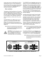
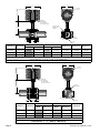
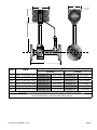
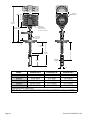
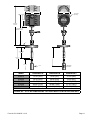
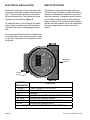
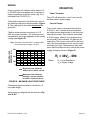
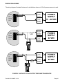
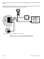
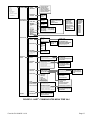
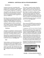
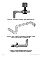
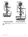
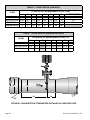
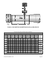
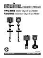
Operator’s Manual
RWG/RWS Wafer-Style Flow Meter
RNG/RNS Insertion-Style Flow Meter
FLOW
Flow
Flow
RV-1000-R5
Tel: 262-639-6770
Toll Free: 888-572-2463
TABLE OF CONTENTS
HEADING
PAGE
INTRODUCTION ........................................................................................................................................5
SPECIFICATIONS ......................................................................................................................................5
INSTALLATION ..........................................................................................................................................6
Installation Location ..............................................................................................................................6
Mechanical Installation .........................................................................................................................6
Meter Installation ......................................................................................................................7
Electrical Installation ...........................................................................................................................12
EMC Notification .....................................................................................................................12
Wiring ......................................................................................................................................13
OPERATION.............................................................................................................................................13
Power Terminals .................................................................................................................................13
Current Output ....................................................................................................................................13
HART® Communication ......................................................................................................................14
TROUBLESHOOTING .............................................................................................................................18
Preliminary Checks .............................................................................................................................18
WARRANTY .............................................................................................................................................27
WASTE ELECTRICAL AND ELECTRONIC EQUIPMENT (WEEE) DIRECTIVE .....................................27
LIST OF FIGURES
FIGURE
A
B1
B2
B3
B4
B5
C
D
E
F
G
J
H1
H2
H3
K
L
M
N
TITLE
PAGE
Internal Alignment RWG and RWS Wafer Flow Meters..............................................................7
Outline Dimensions for ½″, 1″, and 1½″ RWG / RWS Wafer Flow Meters ................................8
Outline Dimensions for 2″, 3″, and 4″ RWG / RWS Wafer Flow Meters ....................................8
Outline Dimensions for RWG / RWS Flanged Flow Meters .......................................................9
Outline Dimensions for RNS Insertion Flow Meters .................................................................10
Outline Dimensions for RNG Insertion Flow Meters ................................................................. 11
Flow Meter Terminal Functions.................................................................................................12
Load Resistance Chart .............................................................................................................13
Sensor Wiring Diagram (Without Pressure Transducer) ..........................................................15
Sensor Wiring Diagram (With Pressure Transducer) ...............................................................16
HART® Communicator Menu Tree............................................................................................17
Typical Velocity Profile ..............................................................................................................19
Turbulence Caused by Bend or Obstruction ............................................................................22
Swirl Caused by Two Bends in Different Planes and in Close Proximity to One Another ........22
Upstream/Downstream Sonic Noise Caused by Slightly Opened Control Valves ....................22
Hot Tap Configuration for RNS Insertion Flow Meter ...............................................................23
Hot Tap Configuration for RNG Insertion Flow Meter ...............................................................23
RNS Insertion Flow Meter Installed in a Reduced Pipe ...........................................................24
RNG Insertion Flow Meter Installed in a Reduced Pipe ...........................................................25
Form No. RV-1000-R5 11/10
Page 3
LIST OF TABLES
TABLE
1
2
3
4
5
6
7
TITLE
PAGE
Specifications .............................................................................................................................5
Flow Range Chart for RWG Series Meters ................................................................................6
Flow Range Chart for RWS Series Meters .................................................................................6
Flow Range Chart for RNG Series Meters .................................................................................6
Flow Range Chart for RNS Series Meters .................................................................................6
Flow Profile (Raw Data) ...........................................................................................................24
Flow Profile (Normalized Data) ................................................................................................24
LIST OF APPENDIXES
APPENDIX
A
TITLE
PAGE
ADDITIONAL INSTALLATION REQUIREMENTS ....................................................................19
Introduction ......................................................................................................................................19
Turbulence .......................................................................................................................................19
Swirl .................................................................................................................................................19
Sonic Noise .....................................................................................................................................19
Velocity Profile .................................................................................................................................19
Straight-Run Piping Considerations ................................................................................................20
Temperature and Pressure Tap Locations .......................................................................................20
Wafer-Style Sensor Installation .......................................................................................................20
Insertion-Style Sensor Installation ...................................................................................................20
Fixed Insertion Flow Meter Installation ............................................................................................21
Hot Tap Insertion Flow Meter Installation.........................................................................................21
Flow Profiling ...................................................................................................................................21
Reducing the Pipe Diameter ............................................................................................................21
B
CERTIFICATION DOCUMENTS ..............................................................................................26
CE-ATEX Declaration of Conformity ................................................................................................26
Page 4
Form No. RV-1000-R5 11/10
INTRODUCTION
The RNx/RWx series vortex shedding flow meter family is designed to provide accurate and
repeatable gas or steam flow measurement.
These meters employ a patented ultrasonic
technique to measure a form of turbulence created in the flow stream. This turbulence, known
as the Von Karman Vortex Street, is related to
the flow through the pipe.
The RNx/RWx series flow meter is a digital
signal processing device, with HART® compatible communications. The primary output of the
meter is a 2 wire, 4-20 milliampere (mA) current
which is proportional to the flow.
With HART® Communications, users have the
capability to remotely configure the meter. Typical operations, like re-scaling the analog output,
can be performed in comfort using a standard
PC or HART® 275/375 Communicator.
The wafer-style meters are for pipe diameters
four inches or less, and are installed between
150 lb. flanges, or are manufactured with pipe
extensions and 150 lb. (300 lb. optional) flanges
welded on the ends. These meters are calibrated in volumetric flow units, e.g. Actual Cubic
Feet per Minute (ACFM). Flow rates for the
wafer-style meters are listed in Tables 2 and 3.
The insertion-style meters are retractable meters that are installed through the wall of a pipe
or duct larger than four inches. These meters
can be installed through a 2″ full port valve,
which permits the unit to be retracted or inserted manually without shutting down the system.
DANGER: Caution should be used
when inserting or retracting at pressures exceeding 60 PSIG (4.14
BARg).
Flow rates for the insertion-style meters are shown
in Tables 4 and 5.
TABLE 1 - SPECIFICATIONS
Parameter
Mounting
Requirements
Wafer
Gas / Air
Insertion
Steam
Steam
Mounts between two 150 lb. flanges
Gas / Air
Options for 2" NPT, 2" 150# Flange,
2" 300# Flange, DN50 Flange
Operating
Pressure
-5 to +250 PSIG
(-0.34 to +17 BARg)
-5 to +150 PSIG (-0.34 to +10.3 BARg)
-5 to +250 PSIG
(-0.34 to +17 BARg)
Operating
Temperature
-20 °F to +360 °F
(-28 °C to +182 °C)
-20 °F to +366 °F(-28 °C to +186 °C)
-20 °F to +300 °F
(-28 °C to +149 °C)
Ambient
Temperature
-20 °F to +155 °F (-28 °C to +68 °C)
Accuracy
±1% of Reading over the upper 90% of the flow range
Repeatability
0.5% of Reading
Input Power
+24 VDC*
Output
Primary - 4-20 mA (2 wire)
Load Limits
See Figure D
*The meter requires a minimum of 21 VDC for HART® Communications with a 250 Ω resistor and no load
Form No. RV-1000-R5 11/10
Page 5
TABLE 2: FLOW RANGE FOR RWG SERIES
TABLE 3: FLOW RANGE FOR RWS SERIES
Gas / Air Application
Steam Application
Model
RWG05
RWG10
RWG15
RWG20
RWG30
RWG40
Pipe Size
inch (mm)
Flow ACFM (m³/hr)
Minimum Maximum
Model
Pipe Size
inch (mm)
Flow ACFM (m³/hr)
Minimum Maximum
0.5
1
1.5
2
3
4
0.4 (0.7)
16 (27)
1.2 (2.0)
45 (77)
2.0 (3.4)
100 (170)
5.0 (8.5)
200 (340)
10.0 (17.0) 400 (680)
20.0 (34.0) 600 (1019)
RWS05
RWS10
RWS15
RWS20
RWS30
RWS40
0.5
1
1.5
2
3
4
0.40 (0.7)
1.25 (2.1)
3 (5.1)
5 (8.5)
13 (22.1)
23 (39.0)
(13)
(25)
(38)
(50)
(76)
(102)
(13)
(25)
(38)
(50)
(76)
(102)
10 (17)
35 (59)
100 (170)
160 (272)
320 (544)
480 (816)
TABLE 4: VELOCITY RANGE FOR RNG SERIES
TABLE 5: VELOCITY RANGE FOR RNS SERIES
Gas / Air Application
Steam Application (see Notes)
Model
Pipe Size
inch (mm)
Velocity - fps (mps)
Minimum
Maximum
Model
Pipe Size
inch (mm)
Velocity - fps (mps)
Minimum Maximum
6 (152)
4 (102)
8 (203)
6 (152)
RNS
5 (1)
125 (38)
RNG
2 (0.6)
140 (43)
10 (254)
8 (203)
12 (305)
10 (254)
Flow measured in feet / second @ 14.69 PSIA, 60 °F (meter / second @ 1.013 BAR, 16 °C)
Notes for Table 5
When pressure is 0 to 25 PSIG, the range is 5 to 125 FPS (1 to 38 MPS).
When pressure is 25 to 60 PSIG, the range is 5 to 158 FPS (1 to 48 MPS).
When pressure is greater than 60 PSIG, the range is 5 to 175 FPS (1 to 53 MPS).
INSTALLATION
The flow meter is shipped completely assembled, tested and ready to install in its permanent
location. See Figures B1 thru B5 for the applicable outline dimensions for specific meters.
Installation Location
The RNx/RWx series meters use ultrasonics to
measure flow. An ultrasonic noise can interfere
with this technique, therefore high intensity,
ultrasonic noise sources should not be located
upstream or downstream from the meter. Common mechanical ultrasonic noise sources
include the following:
Page 6
● Slightly cracked valves operating with
large pressure drops.
● Small pipe leaks in high pressure systems.
● Venturies operating at near-sonic flow
rates.
● Sonic nozzles.
If these ultrasonic noise sources cannot be
eliminated, the meter should be mounted with
at least one elbow between the flow meter and
the noise source.
Mechanical Installation
The meter should be installed with at least 20
pipe diameters of straight pipe upstream and
10 pipe diameters downstream. This condition
provides the fully developed, symmetrical flow
profile that is necessary to obtain accurate and
repeatable results. Shorter upstream/downForm No. RV-1000-R5 11/10
stream piping may be used although a shift in
calibration may occur. If severe turbulence or
distorted flow profiles are present, flow straighteners should be used. See Appendix A for
additional installation information.
Meter Installation
The labeling of the flow direction on the meter
should be aligned with the flow in the pipe. If liquids or condensate can be present in the flow,
the meter should be installed so that liquids will
not accumulate on the ultrasonic transducers
(the small buttons on either side of the vortex
strut).
The RNS/RNG series insertion meters are designed to mount on a standard ANSI 150 lb., 2″
pipe flange. The measuring window should be
installed in the center of the line for line sizes
12 inches or less (see Figures B4 and B5). For
line sizes larger than 12 inches, the measuring
window should be installed 25% to 50% of the
way into the pipe. It is recommended that the
internal dimensions of the line be measured for
accurate readings.
The RWG/RWS series wafer meters are designed to mount between two ANSI 150 lb.
flanges. The meter should be mounted so its
inside diameter is centered inside the pipe (see
Figure A).
Insertion meters can be used in any size pipe
four inches and larger in diameter. In order to
calculate accurate volumetric, mass, and standard flow measurements, it is recommended
to enter the exact pipe size into the meter.
Normally this operation, along with overall
meter configuration, is performed at the factory.
However, the user can enter the pipe diameter
on site using the Racine HART Interface or a
HART® 275/375 communicator.
Note: Gaskets (not provided) are necessary between
the sensor and the ANSI flanges. Ensure that
these gaskets are properly installed and do not
protrude into the flow stream.
Note: The torque requirement for the fitting is 50-60
ft. lbs. (see Figures B4 & B5). See Appendix
A for additional installation information and
flow profiling.
CAUTION: Avoid bending the vortex
strut or damaging the transducers
during installation. Do not remove
cover plates while unit is operating.
The RWGxxF/RWSxxF series flanged meters
are designed to mount between two ANSI 150
lb. flanges (300 lb. optional) (see Figure B3).
Note: Gaskets (not provided) are necessary between
the ANSI flanges. Ensure that these gaskets
are properly installed and do not protrude into
the flow stream.
CORRECT
(Meter Centered In Pipe)
Flow
INCORRECT
(Meter Not Centered In Pipe)
Flow
FIGURE A - INTERNAL ALIGNMENT OF WAFER STYLE FLOW METERS
Form No. RV-1000-R5 11/10
Page 7
5.75
4.50
3/4-14 NPT
Pipe Plug
4.38"
Cable Entry
Accommodates
.19/.25 Dia Cable
3/4 -14 NPT Connector
.531 Dia 4 Holes
Spaced at 90° on
D Dia BC
C +.12
-.00
Flow
Flow
E Dia
Both Sides
B Dia
.06
Diameter A
Diameter B
3.50 (89)
2.25
.06
A Dia
GAS/AIR
STEAM
Dimension D
Dimension E
Dimension F
2.38 (61)
2.25 (57)
1.38 (35)
Model
Dimension C
Model
Dimension C
0.50 (13)
RWG05
5.60 (142)
RWS05
9.47 (241)
3.97 (101)
0.88 (22)
RWG10
5.78 (147)
RWS10
9.65 (245)
3.12 (79)
2.12 (54)
2.00 (51)
4.72 (120)
1.38 (35)
RWG15
6.34 (161)
RWS15
10.21 (259)
3.88 (99)
2.12 (54)
2.88 (73)
All dimensions are in inches (mm)
FIGURE B1 - ½″, 1″, AND 1½″ METERS
5.75
4.50
3/4-14 NPT
Pipe Plug
4.38"
Cable Entry
Accommodates
.19/.25 Dia Cable
3/4 -14 NPT Connector
D Dia
Both Sides
+.12
C -.00
Flow
Flow
B Dia
.06
2.25
.06
A Dia
GAS/AIR
Diameter A
Diameter B
3.97 (101)
STEAM
Diameter D
Model
Dimension C
Model
Dimension C
1.75 (45)
RWG20
5.92 (150)
RWS20
9.79 (249)
5.22 (133)
2.75 (70)
RWG30
6.62 (168)
RWS30
10.49 (267)
4.55 (116)
6.87 (174)
3.75 (95)
RWG40
7.52 (191)
RWS40
11.39 (289)
6.19 (157)
3.15 (80)
All dimensions are in inches (mm)
FIGURE B2 - 2″, 3″, AND 4″ METERS
Page 8
Form No. RV-1000-R5 11/10
4.50
5.75
3/4-14 NPT
Pipe Plug
4.69"
A
by HEDLAND
SENSOR S.N.: 64
PRESSURE SENSOR:
OUTPUT: 4 - 20 mA
FLOW
FLOW
B
DIM A
SIZE
DIM B
½″
1″
1½″
2″
3″
4″
9.88 - 10.00 (250- 254)
9.88 -10.00 (250- 254)
9.88 -10.00 (250- 254)
9.88 -10.00 (250- 254)
11.88 - 12.00 (301- 304)
11.88 - 12.00 (301- 304)
GAS/AIR
RWG05F15*
RWG10F15*
RWG15F15*
RWG20F15*
RWG30F15*
RWG40F15*
5.60 (142)
5.78 (147)
6.34 (161)
5.92 (150)
6.62 (168)
7.52 (191)
STEAM
RWS05F15*
RWS10F15*
RWS15F15*
RWS20F15*
RWS30F15*
RWS40F15*
9.47 (241)
9.65 (245)
10.21 (259)
9.79 (249)
10.49 (267)
11.39 (289)
All dimensions are in inches (mm)
FIGURE B3 - OUTLINE DIMENSIONS FOR FLANGED SERIES METERS
*150 lb. RF ANSI Flange - 300 lb. RF ANSI Flange optional
Form No. RV-1000-R5 11/10
Page 9
4.50
5.75
3/4-14 NPT
Pipe Plug
4.38"
C Maximum
Retracted
Cable Entry
Accommodates
.19/.25 Dia Cable
3/4 -14 NPT Connector
13.0" Maximum at
Maximum Insertion
FLOW
Fitting Torque
Requirements
50-60 ft.-lbs.
.75"
6.10" Maximum
Retracted
A
B Maximum
Insertion
6.10"
Maximum
Measuring
Window
1.63"
Model
Dimension A
Dimension B
Dimension C
RNS12
RNS24
RNS36
RNS48
RNS60
12.00 (305)
24.00 (609)
36.00 (914)
48.00 (1218)
60.00 (1524)
15.0 (381)
27.0 (685)
39.0 (990)
51.0 (1295)
63.0 (1600)
21.5 (546)
33.5 (850)
45.5 (1154)
57.5 (1459)
69.5 (1765)
All dimensions are in inches (mm)
FIGURE B4 - OUTLINE DIMENSIONS FOR RNS INSERTION STEAM METERS
Page 10
Form No. RV-1000-R5 11/10
4.50
5.75
3/4-14 NPT
Pipe Plug
4.38"
C Maximum
Retracted
13.0" Maximum at
Maximum Insertion
FLOW
.75"
4.50" Maximum
Retracted
B Maximum
Insertion
A
4.50"
Maximum
Measuring
Window
FLOW
Model
Dimension A
Dimension B
Dimension C
RNG12
RNG24
RNG36
RNG48
RNG60
12.00 (305)
24.00 (609)
36.00 (914)
48.00 (1218)
60.00 (1524)
12.88 (327)
24.88 (632)
36.88 (937)
48.88 (1242)
60.88 (1546)
21.50 (546)
33.50 (851)
45.50 (1156)
57.50 (1461)
69.50 (1765)
All dimensions are in inches (mm)
FIGURE B5 - OUTLINE DIMENSIONS FOR RNG INSERTION AIR/GAS METERS
Form No. RV-1000-R5 11/10
Page 11
ELECTRICAL INSTALLATION
EMC NOTIFICATION
Electrical connections for the meter are made
using screw terminals located inside the enclosure. To access these terminals, remove the
lid from the enclosure. The functions of these
terminals are illustrated in Figure C.
The ultrasonic sensing technology employs a
160 KHz carrier frequency and the flow meter is
sensitive to radiated and conducted noise at or
near this frequency. Precautions must be taken
not to subject the flow meter or associated cabling to sources of RF noise that could interfere
with the ultrasonic carrier. Any such interference
can cause degradation in flow meter performance.
To install the cable, route it through the cable
entry located on either side of the enclosure
and attach the wires to the appropriate terminals.
It is recommended that a wire be attached from
the external flow meter ground terminal to chassis ground, if the pipe is not connected to chassis ground.
+
4-20MA
NC
EP RTN
EP PWR
EP OUT
EP IN
Cable Shield
Ground
Chassis
Ground
TERMINAL
DESIGNATOR
FUNCTION
4-20mA +
LOOP POWER (+15 to 24 VDC)
4-20mA LOOP POWER (-)
NC
not used
EP RTN
PRESSURE SENSOR POWER SUPPLY RETURN
EP PWR
PRESSURE SENSOR POWER
EP OUT
POWER OUT TO PRESSURE SENSOR
EP IN
PRESSURE SENSOR INPUT
FIGURE C - FLOW METER TERMINAL FUNCTIONS
Page 12
Form No. RV-1000-R5 11/10
WIRING
A two conductor foil shielded cable made of 14
to 22 AWG solid or stranded wire is required to
make connections to the flow meter (e.g. Consolidated Wire P/N 5573-CL).
The shield is required to be attached to one of
the shield ground points as illustrated in Figure
C. The other end of the shield should not be
grounded.
The flow meter requires a minimum of +15
VDC for proper operation. The maximum load
resistance for the power depends on the supply
voltage (see Figure D).
Note: The When used with HART ® Communication,
the minimum input voltage is 21 VDC.
MAXIMUM LOAD
RESISTANCE (W)
450
OPERATION
Power Terminals
The 4-20 mA terminals (+ and -) are used for
the flow meter’s power supply.
Current Output
The current output is accessed through the
4-20 mA + and - terminal loop and provides
an output current proportional to the flow measured by the meter. This output is a standard
4-20 mA output, where 4 mA corresponds to
no flow and 20 mA indicates 100 percent (full
scale) flow. The current output will not be accurate if the load resistance on the current output
terminal is too high. The maximum load resistance that the meter can drive versus the power
supply voltage is shown in Figure D.
RL = 46VS - 690
250
Where:
100
0
16
20
RL = Load Resistance
VS = Supply Voltage
24
Maximum Load resistance
without 250 : HART® resistor
Maximum Load resistance
with 250 : resistor installed
for HART® Communications
FIGURE D - MAXIMUM LOAD RESISTANCE
The external pressure sensor is limited to a 5
foot cable length.
Various wiring configurations are shown in Figures E & F.
Form No. RV-1000-R5 11/10
Page 13
HART® Communication
The Racine vortex meter has the capability of
HART® Communication. However, it is not required that it be used. In most cases, the meter
is configured at the factory per the customer’s
specifications. The user need only install the
meter and connect power.
If HART Communication is desired, it is required that a resistor be placed in the current
loop.
®
The value of the resistor can range from 250
to 350 Ω and be rated at ¼ watt or larger. The
placement of the resistor is illustrated in the wiring diagrams. The resistor will add to the total
loop resistance and will raise the value of the
required power supply voltage. With a resistor
in place, Racine Vortex recommends a maximum of 24 VDC supply. This power supply voltage will accommodate 164 Ω of loop resistance
in addition to a 250 Ω communication resistor.
For high loop resistance, consult Figure D for
the required supply voltage.
There are two ways to communicate to the
meter via the HART® interface: the Racine
HART Interface or a HART® Communicator. The
Racine HART Interface is a PC based software
program that runs on Windows 98, Windows
NT, Windows ME, Windows XP, Windows Vista®
and Windows® 7 operating systems.
This program will provide access to all the settings that can be configured by the user. It also
provides tools for diagnostics and trimming the
analog output.
The Racine HART Interface requires a HART®
modem to convert the modulated HART® signal
to the RS-232 communication standard. See
the Racine HART Interface User’s Manual for
more information about the Racine HART Interface.
The HART® 275/375 Communicator is a handheld device that can communicate with any
HART® device that is registered with the HART®
Communication Foundation. The HART® 275/
375 Communicator also provides access to
all settings that can be configured by the user.
The 275 provides a menu driven interface. See
Figure G to view the menu map for the HART®
275 Communicator.
Note: HART ® 275 Communicator requires Racine
vortex drivers for proper communications.
(See communicator owner’s manual for driver
listing).
Page 14
Form No. RV-1000-R5 11/10
WIRING DIAGRAMS
The wiring diagrams illustrated below are for installations where no 4-20 mA pressure sensor is used.
FLOW
INDICATOR
- OR CONTROL
SYSTEM
4-20mA+
4-20mANC
EP RTN
EP PWR
EP OUT
EP IN
FLOW
INDICATOR
- OR CONTROL
SYSTEM
4-20mA+
4-20mANC
EP RTN
EP PWR
EP OUT
EP IN
250 7
FLOW
INDICATOR
- OR CONTROL
SYSTEM
FLOW
INDICATOR
- OR CONTROL
SYSTEM
POWER
SUPPLY
15 - 24 VDC
POWER
SUPPLY
24 VDC
HART
Fieldbus
COMMUNICATIONS PROTOCOL
oundation
Page
Up
BK sp
Delete
Page
Dn
#%&
ABC
Copy
Paset
1
2
GHI
4
7
,(
)
3
MNO
+Hot Key
TUV
WXYZ
8
,
DEF
Hot Key
JKL
Insert
5
PQRS
<>
0
6
9
WXYZ
_
FIELD COMMUNICATOR
FLOW
INDICATOR
- OR CONTROL
SYSTEM
4-20mA+
4-20mANC
EP RTN
EP PWR
EP OUT
EP IN
250 7
FLOW
INDICATOR
- OR CONTROL
SYSTEM
POWER
SUPPLY
24 VDC
HART
Fieldbus
COMMUNICATIONS PROTOCOL
oundation
Page
Up
BK sp
Delete
Page
Dn
#%&
ABC
Copy
Paset
1
GHI
4
PQRS
7
,(
,
)
2
DEF
3
Hot Key
JKL
MNO
Insert
+Hot Key
TUV
WXYZ
5
8
<>
0
6
9
WXYZ
_
FIELD COMMUNICATOR
FIGURE E - WITHOUT 4-20 mA OUTPUT PRESSURE TRANSDUCER
Form No. RV-1000-R5 11/10
Page 15
If an analog pressure sensor is used, it must be wired as shown below to avoid inadvertent current
paths.
A single supply can be used to power the flow meter and the external pressure sensor. The 4-20 mA
flow indication must be taken from the source side of the loop.
HART
Fieldbus
COMMUNICATIONS PROTOCOL
oundation
Page
Up
BK sp
Delete
Page
Dn
#%&
ABC
Copy
Paset
1
2
GHI
4
7
,(
)
3
MNO
+Hot Key
TUV
WXYZ
8
,
DEF
Hot Key
JKL
Insert
5
PQRS
<>
0
6
9
WXYZ
_
FIELD COMMUNICATOR
4-20mA+
4-20mANC
EP RTN
EP PWR
EP OUT
EP IN
250 W
FLOW
INDICATOR
- OR CONTROL
SYSTEM
POWER
SUPPLY
24 VDC
PRESSURE
SENSOR
V+
RTN
Note: Pressure sensor’s cable length is limited to 5 feet (1.5 m).
FIGURE F - WITH 4-20 mA OUTPUT PRESSURE SENSOR
Page 16
Form No. RV-1000-R5 11/10
1
2
3
4
5
6
DEVICE SETUP
PV
AO
LRV
URV
Edit Mode
On / Off
7 Enable / Disable
Edit Mode
1 PROCESS
VARIABLES
2 DIAGNOSTICS
AND SERVICE
1 VIEW FIELD
DEVICE
VARIABLES
1
2
3
4
5
6
2 TOTALIZER
CONTROL
1 Total
2 Start / Stop
3 Reset
1 TEST / STATUS
1 View Status
2 Self Test
2 LOOP TEST
3 REVISION
NUMBERS
4 Flow
Profiling
(Method)
5 VOLTAGE
LEVELS
6 PRODUCT
INFORMATION
7 DEBUG
INFORMATION
3 BASIC SETUP
4 DETAILED
SETUP
1
2
3
4
1 Fixed Current
2 D/A Trim
Universal Cmd Revision
Specific Cmd Revision
PV Unit
Select PV Unit
1
2
3
4
5
6
7
8
9
Model Number
Part Number
Meter Style
Sensor Option
Display Option
Model Deviation
Modification Date
Strut Size
Calibration Date
1
2
3
4
AGC Voltage
APP Voltage
ADC Voltage
UPP Voltage
1
2
3
4
PV Type
SELECT PV TYPE
PV Unit
SELECT PV UNIT
3 RANGE VALUE
1
2
3
4
5
URV
LRV
Min Span
USL
LSL
4 STANDARD
CONDITIONS
5 PV Damping
6 Pipe ID
1 Base Temperature
2 Base Pressure
1 TEMPERATURE
SETUP
1 TEMPERATURE SOURCE
2 Temperature Unit
3 User Specified Temperatur Value
2 PRESSURE
SETUP
1
2
3
4
5
6
3 CONFIGURE
OUTPUTS
1 PULSE OUTPUT
2 HART OUTPUT
3 LOCAL DISPLAY
1 PULSE MODE
2 User Specified Frequency
3 Frequency URV
4 DEVICE INFO
1
2
3
4
5
6
Manufacturer
Descriptor
Message
Date
Device ID
Write Protect
1
2
3
4
Polling Address
Number of Preambles
Burst Mode
Burst Command
1
2
3
4
5
6
7
8
Process Density
Process Viscosity
Standard Density
PROPERTY SOURCE
User Specified Density Value
User Specified Viscosity Value
Property Table Name
Property Table Version Number
1
2
3
4
5
6
Process Variable
Analog Output
Totalizer
Process Temperature
Process Pressure
Alternating PV & Totalizer
1 Tag
2 PV TYPE
& UNIT
5 FLUID
PROPERTIES
6 Alarm Selection
7 Low Flow Cutoff
5 REVIEW
Process Variable
Analog Output
Percent of Range
Vortex Frequency
Process Temperature
Precess Pressure
8 PASSWORD
PROTECTION
5 UDC Voltage
6 VCC Voltage
7 Loop Voltage
Select from a
dynamic list
of units
PRESSURE SOURCE
Pressure Unit
User Specified Pressure Value
Pressure LRV
Pressure URV
Atmospheric Pressure
1
2
3
4
5
6
MASS FLOW
VOLUME FLOW
STANDARD FLOW
PROCESS TEMPERATURE
PROCESS PRESSURE
Vortex Frequnecy
1
2
3
4
Integrated RTD
External RTD
User Specified Temperature
Steam Table
1
2
3
4
Analog Input - Absolute
Analog Input - Gauge
User Specified Pressure
Steam Table
1
2
3
4
1
2
3
4
5
6
7
8
9
10
11
12
13
MPPS
Rynolds
Strouhal
WDRS
MTE
MPE
FCE
LXP
FCF
DCF
CSP
CFV
CSC
Scaled PV
Fixed Frequency
Vortex Frequency
Off
1 Property Table
2 User Specified Properties
3 Steam Table
1 Protection On / Off
2 Enable / Disable Protection
3 Forgot Password?
FIGURE G - HART ® COMMUNICATOR MENU TREE V4.0
Form No. RV-1000-R5 11/10
Page 17
TROUBLESHOOTING
Racine Vortex flow meters are designed to
ensure long term accuracy and reliability. The
stainless steel body and self-cleaning strut are
specifically designed to withstand the rigors of
industrial environments. As a result, periodic
adjustment or re-calibration is not required.
Technical assistance is available directly from
Racine Vortex, providing complete re-calibration
and repair service for the flow meter at a reasonable cost.
Preliminary Checks
Note: Do NOT open enclosure in hazardous areas
with power applied.
1) Is the flow meter cable installed correctly?
2) Is the proper power supplied to the proper
terminals?
3) Is the flow meter wired for 2 wire 4-20 mA
operation?
Page 18
Form No. RV-1000-R5 11/10
APPENDIX A - ADDITIONAL INSTALLATION REQUIREMENTS
Introduction
Installing a flow meter is something which
requires careful consideration. It cannot just be
placed in a line somewhere and be expected
to fulfill its purpose adequately. The geometry
and condition of the pipe runs in the area of the
installation must be considered to ensure the
best and most accurate operation of the flow
meter. This appendix provides suggestions for
optimum installations.
Most flow meter manufacturers define installation conditions in terms of upstream and downstream straight pipe lengths from the point of
installation. Unfortunately this is not the only
requirement, and one needs to consider other
peripheral conditions, such as proximity and
style of bends, and other equipment installed
in the line. By doing this, you avoid problems of
turbulence, swirl, and sonic noise.
Turbulence
Turbulence is a disturbance of the flow caused
by bends and obstructions in the flow stream (it
is this phenomena which makes the vortex flow
meter work). Fortunately turbulence dies out
fairly quickly, so by positioning the flow meter
well away from bends and obstructions this
potential problem of measuring flow in turbulent
conditions is overcome (see Figure H1).
Swirl
Unlike turbulence, swirl will not die away. Once
created it will continue until dissipated on the
next pipe bend in the system. Swirl occurs after
two bends, in close proximity, which are at an
angle to each other. When designing an installation, keep the flow meter out of any line which
has two adjacent bends upstream (see Figure
H2).
Sonic Noise
Sonic noise is created by valves (either flow
control or pressure control valves) which are
slightly open. Like swirl, sonic noise will only
dissipate on a bend, so it is important to install
flow meters out of the line of sight of valves.
Sonic noise is caused by liquid attaining sonic
velocities through a slightly open valve that
has a pressure difference across it. This noise
travels both upstream and downstream from the
valve so you have to ensure that the flow meter
is installed well away from the valve, preferably
around a bend (see Figure H3).
Velocity Profile
When using an RNG/RNS series insertion flow
meter, it is necessary to consider the effects of
the velocity profile across the pipe or duct to
optimize accuracy.
In large pipes, the flow moves slowly at the pipe
walls but is at maximum velocity in the center of
the pipe creating a continuously variable velocity across the pipe (see Figure J). This velocity
variation is called the velocity profile of the pipe,
and can be measured and plotted by using the
insertion flow meter to measure velocities at
various noted positions across the pipe. As the
maximum velocity is in the center of the pipe,
it follows that if the flow meter is positioned in
the center, it will not measure average flow. The
“rule of thumb” position is 25% of the way into
the pipe, but the optimum position can only be
obtained by measuring the profile and working
out the correct position from that.
1⁄8
¼
½
Flow
FIGURE J - TYPICAL VELOCITY PROFILE
Form No. RV-1000-R5 11/10
Page 19
Straight-Run Piping Considerations
The sensor should be installed with 20 diameters, or more, of straight, unobstructed, full area
pipe upstream of the flow meter installation
and 10 diameters, or more, downstream. This
condition provides the fully developed, symmetrical flow profile that is necessary to obtain
accurate and repeatable results. The first obstruction upstream and downstream should be
a full area elbow. If the minimum straight run is
not possible, the general rule is to have 80% of
the straight run upstream and 20% downstream
from the flow meter installation.
High intensity ultrasonic noises should not be
located upstream or downstream from the sensor. Common ultrasonic noise sources include
the following:
● Slightly cracked valves operating with
large pressure drops.
● Small pipe leaks in high pressure systems.
● Venturies operating at near-sonic flow
rates.
● Sonic nozzles.
If these ultrasonic noise sources cannot be
eliminated, the meter should be mounted with
at least one elbow between the flow meter and
the noise source.
Temperature and Pressure Tap Locations
User supplied pressure and temperature sensors should be mounted downstream from the
flow meter. The pressure sensor should be approximately 3-5 pipe diameters and the temperature sensor approximately 4-8 pipe diameters
downstream.
Page 20
Wafer-Style Sensor Installation
The flow meter is shipped completely assembled, tested and ready to install and operate in
its permanent location. The RWG/RWS waferstyle flow meters are designed to mount between two ANSI flanges. The flow meter should
be mounted so its inside diameter is centered
inside the pipe. The labeling of the flow direction of the flow meter should be aligned with the
flow in the pipe.
Note: Gaskets (not provided) are necessary between
the sensor and ANSI flange. It is recommended that the customer conduct a flow profile
survey prior to installing flow meter.
Insertion-Style Meter Installation
The flow meter is shipped completely assembled, tested and ready to install and operate in
its permanent location.
If the main line can be depressurized easily,
then a simple installation, consisting of a 2″
(51 mm) nozzle and a standard ANSI 150 lb.,
2″ pipe flange may be used. This permits the
shortest shaft length to be used, which keeps
clearance space requirements for insertion and
removal to a minimum.
Note: Gaskets (not provided) are necessary between
the sensor and ANSI flange. It is recommended that the customer conduct a flow profile
survey prior to installing flow meter.
DANGER - Caution should be used
when inserting or retracting at pressures exceeding 60 PSIG (4.14
BARg).
Form No. RV-1000-R5 11/10
Hot Tap Insertion Flow Meter Installation
Where de-pressurizing the line for flow meter maintenance is impossible or undesirable,
the “hot tap” method of installation is used.
This method involves inserting the flow meter
through a 2″ (51 mm) spool piece and a 2″ (51
mm) full port valve and will require a longer
shaft length as well as greater clearance space
for removal and installation.
DANGER - Caution should be used
when inserting or retracting at pressures exceeding 60 PSIG (4.14
BARg).
Figures K & L show a sample hot tap installation. With the exception of the spool piece,
which must be a minimum of 6″ (152.4 mm)
Figure K in length, or a minimum of 4.5″ (114.3
mm) Figure L, all of the dimensions are suggestions only. Actual dimensions may vary
depending on customer’s own hot tap configuration.
To calculate the required insertion flow meter's
stem length:
For pipe diameters less than or equal to 24″
(609 mm):
Calculate the distance from the center line of
the pipe to the top of the flow meter mounting
flange.
For pipe diameters greater than 24″ (609 mm):
Calculate the distance from the top of the flow
meter flange to a point ¼ of the pipe diameter
into the pipe.
Flow Profiling
If the flow meter is long enough to be inserted
to the far side of the pipe, the flow through the
pipe may be profiled at various flow rates. The
goal is to find a point in the pipe that remains a
consistent percentage of the average flow rate
over a wide range of flow. A sample flow profile
is shown in Table 6. In this example, the flow
rate of a 48″ pipe is measured every six inches
across the diameter of the pipe beginning and
ending 3″ from the near and far sides of the
pipe. The distance in inches from the nearside of the pipe is shown. Measurements are
taken at a low, medium and high average flow.
In Table 7 the flow rate at each measurement
point has been converted to a percentage of the
average flow. It can be seen that point number
three (15″ from the near side of the pipe) reads
a consistent 102 percent of the average flow.
The meter should be placed in this position and
the output should be divided by 1.02 to obtain
the correct reading. Flow profiling will generally
improve measurement quality in insertion meter
installations.
Reducing the Pipe Diameter
To decrease the variation of flow profile, the piping can be narrowed at the flow meter as shown
in Figures M & N. This will smooth the flow
and increase the effectiveness of flow profiling.
Nearly any angle can be used on the downstream side of the meter to restore the original
pipe diameter. However, if the angle of piping is
seven degrees or less, nearly all the pressure
drop caused by the narrow pipe section will be
recovered.
When flow profiling is required, calculate the
distance from the bottom of the pipe to the top
of the flow meter mounting flange and subtract
2″ (51 mm). Next round this distance up to the
next largest 12″ (305 mm) increment. This is the
stem length that should be ordered.
Form No. RV-1000-R5 11/10
Page 21
Flow
Flow
FIGURE H1 - TURBULENCE CAUSED BY BEND OR OBSTRUCTION
FIGURE H2 - SWIRL CAUSED BY TWO BENDS IN DIFFERENT PLANES
AND IN CLOSE PROXIMITY TO ONE ANOTHER
FIGURE H3 - UPSTREAM/DOWNSTREAM SONIC NOISE
CAUSED BY SLIGHTLY OPENED CONTROL VALVES
Page 22
Form No. RV-1000-R5 11/10
5.75
5.75
4.38"
Determined
By Stem
Length
4.38"
13.0" Maximum at
Maximum Insertion
Determined
By Stem
Length
Cable Entry
Accommodates
.19/.25 Dia Cable
3/4 -14 NPT Connector
FLOW
13.05" Maximum at
Maximum Insertion
Standard ANSI
2 Inch 150 Lb. Flange
Cable Entry
Accommodates
.19/.25 Dia Cable
3/4 -14 NPT Connector
FLOW
Standard ANSI
2 Inch 150 Lb. Flange
6.10" Maximum
Retracted
Spool Piece
6.00" Minimum
4.50" Maximum
Retracted
Spool Piece
4.50" Minimum
2" Full Port
Valve
Determined
By Stem
Length
2" Full Port
Valve
6.10"
Maximum
Determined
By Stem
Length
Flow
4.50"
Maximum
FIGURE K - HOT TAP CONFIGURATION
RNS INSERTION STEAM METERS
Flow
FIGURE L - HOT TAP CONFIGURATION
RNG INSERTION GAS METERS
DANGER - Caution should be used when inserting or retracting at pressures exceeding
60 PSIG (4.14 BARg).
Form No. RV-1000-R5 11/10
Page 23
TABLE 6 - FLOW PROFILE (RAW DATA)
FLOW RATE AT MEASUREMENT POINT (FPS)
FLOW
1
2
3
4
5
6
7
8
AVERAGE (FPS)
LOW FLOW
1.90 2.00 2.04 2.06 2.06 2.04 2.00 1.90
MEDIUM FLOW 5.58 5.91 6.12 6.21 6.24 6.18 6.06 5.70
HIGH FLOW
10.92 11.70 12.24 12.48 12.60 12.48 12.18 11.40
DISTANCE (in)
3
9
15
21
27
33
39
45
2.0
6.0
12.0
TABLE 7 - FLOW PROFILE (NORMALIZED DATA)
FLOW RATE AT MEASUREMENT POINT (%)
FLOW
1
LOW FLOW
95.0
MEDIUM FLOW 93.0
HIGH FLOW
91.0
2
3
4
5
6
7
8
100.0 102.0 103.0 103.0 102.0 100.0 95.0
98.5 102.0 103.5 104.0 103.0 101.0 95.0
97.5 102.0 104.0 105.0 104.0 101.5 95.0
FLOW
D
30°
Flow
d
3d
1d
7°
FIGURE M - RNS INSERTION STEAM METER INSTALLED IN A REDUCED PIPE
Page 24
Form No. RV-1000-R5 11/10
FLOW
Flow
d
D
3d
30°
1d
7°
FIGURE N - RNG INSERTION GAS METER INSTALLED IN A REDUCED PIPE
Pressure Drop Data for Wafer Style Gas Meters
Flow Range in SCFM for Air at 60 °F
Flow Range in Nm3/hr for Air at 15.6 °C
PSI
(Bar)
Pipe
Size
0
(0)
25
(1.7)
50
(3.5)
75
(5.2)
100
(6.9)
150
(10.3)
200
(13.8)
250
(17.2)
MIN
MAX
MIN
MAX
MIN
MAX
MIN
MAX
MIN
MAX
MIN
MAX
MIN
MAX
MIN
MAX
½″
13 mm
0.4
16
1
43
2
70
2
82
3
83
4
82
6
82
7
82
1
27
2
73
3
119
3
139
5
141
7
139
10
139
12
139
1″
25 mm
1
45
3
121
6
198
8
274
10
351
14
504
18
507
23
507
2
76
5
206
10
336
14
466
17
596
24
856
31
861
39
861
1½″
38 mm
2
100
7
270
11
440
15
610
20
780
28
1120
37
1253
45
1253
3
170
12
459
19
748
25
1036
34
1325
48
1903
63
2129
76
2129
2″
50 mm
5
200
14
540
22
880
31
1220
39
1560
56
2030
73
2030
90
2030
8
340
24
917
37
1495
53
2073
66
2650
95
3449
124
3449
153
3449
3″
76 mm
10
400
27
1080
44
1760
61
2441
78
3121
112
4247
146
4247
180
4247
17
680
46
1835
75
2990
104
4147
133
5303
190
7216
248
7216
306
7216
4″
102 mm
20
600
54
1620
88
2641
122
3662
156
4682
224
6724
292
7897
360
7897
34
1019
92
2752
150
4487
207
6222
265
7955
381
11424
496
13417
612
13417
Pressure
Drop at 50%
of Maximum
Flow*
in H2O
(Bar)
1.40
(3.47 x 10⁻³)
1.00
(2.49 x 10⁻³)
0.65
(1.62 x 10⁻³)
0.35
(8.72 x 10⁻⁴)
0.25
(6.23 x 10⁻⁴)
0.25
(6.23 x 10⁻⁴)
* Pressure drop data for air at 14.696 PSI at 60 °F (0 Bar at 15.6 °C)
Form No. RV-1000-R5 11/10
Page 25
APPENDIX B - CERTIFICATION DOCUMENTS
8635 Washington Avenue, Racine, WI 53406-3738
Phone: (262)-639-6770 Fax: (262)-639-2267 Website: www.racinefed.com
Declaration of Conformity
Manufacturer's Name:
Racine Federated Inc.
Manufacturer's Address:
8635 Washington Avenue
Racine, WI 53406 USA
Declares that the Products:
RWG05, RWG10, RWG15, RWG20, RWG30, RWG40,
RWS05, RWS10, RWS15, RWS20, RWS30, RWS40,
RNG, RNL
(Formerly J-Tec Associates Models: JW7nnn, JW7nnnS,
JI7000, JI8000)
Conform to the following Standards:
Safety:
Emissions:
Immunity:
Directive 94/9/EC
EN 55022
IEC 61000-4-2: 2001
IEC 61000-4-3: 2002
IEC 61000-4-4: 1995
IEC 61000-4-5: 2001
IEC 61000-4-6: 2001
The products listed above are in conformity with the requirements of the EMC Directive
89/336/EEC.
Reference Documents:
SIRA Assessment Report No. R52A18641A
EMC Test Report No. 3042281.011, April 30, 2003, by
Intertek Testing Services
EMC Test Report, May 13, 2003, conducted at Intertek
Testing Services
Test Report, Order No. 200251303, February 19, 2003 by
NEMKO
Supplementary Information:
Date: March 29, 2010
Signature:
Its:
Page 26
Form No. RV-1000-R5 11/10
Division of Racine Federated Inc.
Limited Warranty and Disclaimer
Racine, division of Racine Federated Inc. warrants to the end purchaser, for a period of one year
from the date of shipment from the factory, that all flow meters, electronic accessories and other
products manufactured by it are free from defects in materials and workmanship. This warranty does
not cover products that have been damaged due to misapplication, abuse, lack of maintenance, or
improper installation. Racine’s obligation under this warranty is limited to the repair or replacement
of a defective product, at no charge to the end purchaser, if the product is inspected by Racine and
found to be defective. Repair or replacement is at Racine’s discretion. A returned goods authorization
number must be obtained from Racine before any product may be returned for warranty repair or
replacement. The product must be thoroughly cleaned and any process chemicals removed before
it will be accepted for return.
The purchaser must determine the applicability of the product for its desired use and assumes all
risk in connection therewith. Racine assumes no responsibility or liability for any omissions or errors
in connection with the use of its products. Racine will under no circumstances be liable for any
incidental, consequential, contingent or special damages or loss to any person or property arising
out of the failure of any product, component or accessory.
All expressed or implied warranties, including the implied warranty of merchantability and the
implied warranty of fitness for a particular purpose or application are expressly disclaimed
and shall not apply to any products sold or services rendered by Racine.
The above warranty supersedes and is in lieu of all other warranties, either expressed or implied
and all other obligations or liabilities. No agent or representative has any authority to alter the terms
of this warranty in any way.
Waste Electrical and Electronic Equipment (WEEE) Directive
In the European Union, this label indicates that this product should not be disposed
of with household waste. It should be deposited at an appropriate facility to enable
recovery and recycling.
For information on how to recycle this product responsibly in your country, please
visit:
www.racinefed.com/recycle/
Division of Racine Federated Inc.
8635 Washington Avenue • Racine, WI 53406-3738 USA
Tel: 262-639-6770 or 888-572-2463
Fax: 262-639-2267
e-mail: [email protected]
www.racinevortex.com
Racine is a trademark of Racine Federated Inc.
HART is a registered trademark of the HART Communication Foundation.
WINDOWS and VISTA are registered trademarks of Microsoft Corp.
UL is a registered trademark of Underwriters Laboratories.
© 2010 Racine Federated Inc.
All rights reserved.
Printed in USA
Form No. RV-1000-R5 11/10