1
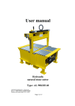
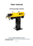
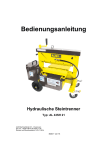
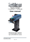
User manual
Hydraulic Block Cutter
Type: AL 43SH 14
ALMI Machinefabriek B.V., Vriezenveen
Doc.no.: 100287-HB-01 AL43SH 14 ENG
Revision and revision date: 3-03-11-2014
Page 1 of 14
Table of contents
1.
2.
3.
4.
5.
6.
7.
8.
9.
Foreword .................................................................................................................................................................................. 3
1.1.
Name of machine........................................................................................................................................................ 3
1.2.
Warning 3
1.3.
Target group for each chapter ..................................................................................................................................... 3
1.4.
Symbols 3
1.5.
Re-ordering the user manual ....................................................................................................................................... 3
1.6.
Deficiencies in this user manual ................................................................................................................................. 3
Introduction .............................................................................................................................................................................. 4
2.1.
The user 4
2.2.
The manufacturer ....................................................................................................................................................... 4
2.3.
Machine identification ................................................................................................................................................ 4
2.4.
Function of the machine ............................................................................................................................................. 5
2.5.
Machine options ......................................................................................................................................................... 5
2.6.
Liability 5
2.7.
Service 5
2.8.
Warranty conditions ................................................................................................................................................... 5
Safety regulations ..................................................................................................................................................................... 5
3.1.
Safety provisions ........................................................................................................................................................ 6
3.1.1. General ......................................................................................................................................................... 6
3.1.2. Emergency stop ............................................................................................................................................ 6
3.1.3. Key switch .................................................................................................................................................... 6
3.1.4. Safety shields................................................................................................................................................ 6
3.2.
Warning symbols on the machine ............................................................................................................................... 6
3.3.
General safety regulations .......................................................................................................................................... 7
3.4.
The operator ............................................................................................................................................................... 7
3.5.
The maintainer............................................................................................................................................................ 7
3.6.
Setup of the machine .................................................................................................................................................. 7
3.7.
The noise emission of the machine ............................................................................................................................. 8
3.8.
Maintenance of the machine ....................................................................................................................................... 8
3.9.
Summary of the safety regulations ............................................................................................................................. 8
Description ............................................................................................................................................................................... 8
4.1.
General 8
4.2.
Construction of the machine ....................................................................................................................................... 8
4.3.
Electrical supply ......................................................................................................................................................... 9
4.4.
Safety provisions and warning symbols...................................................................................................................... 9
4.5.
Controls and adjustments............................................................................................................................................ 9
4.6.
Operation .................................................................................................................................................................... 9
4.7.
Technical data .......................................................................................................................................................... 10
Scope of delivery, transport, storage, placement and initial setup .......................................................................................... 10
5.1.
Scope of delivery ...................................................................................................................................................... 10
5.2.
Transport and storage ............................................................................................................................................... 10
5.3.
Placement of the machine ......................................................................................................................................... 10
5.4.
Initial setup ............................................................................................................................................................... 10
Operation................................................................................................................................................................................ 10
6.1.
Placement and movement ......................................................................................................................................... 11
6.2.
Operation in general ................................................................................................................................................. 11
6.3.
Start up 11
6.4.
Shut down................................................................................................................................................................. 11
Maintenance ........................................................................................................................................................................... 11
7.1.
Precautionary measures ............................................................................................................................................ 11
7.2.
Checkpoints .............................................................................................................................................................. 12
7.3.
Replacement of components ..................................................................................................................................... 12
Trouble ................................................................................................................................................................................... 13
8.1.
General information for trouble ................................................................................................................................ 13
8.2.
Trouble indications and signals ................................................................................................................................ 13
Disposal.................................................................................................................................................................................. 13
Table 1.3-1: Overview of the target groups for each chapter ............................................................................................................... 3
Table 7.2-1: Checkpoints and lubrication schedule ........................................................................................................................... 12
Figure 2.3-1: Sample type plate with CE-mark.................................................................................................................................... 4
Figure 2.3-2: Location of the type plate and serial number.................................................................................................................. 5
Figure 3.2-1: Warning symbols on the machine .................................................................................................................................. 7
Figure 4.2-1: Construction of the machine .......................................................................................................................................... 9
Figure 6.3-1: Pictogram "placing the stone in the middle of the blade" ............................................................................................. 11
Appendix: ......................................................................................................................... EU Declaration of Conformity for machines
Appendix: ............................................................................................. Exploded view drawing with drawing number 1.0435.000 1A
ALMI Machinefabriek B.V., Vriezenveen
Doc.no.: 100287-HB-01 AL43SH 14 ENG
Revision and revision date: 3-03-11-2014
Page 2 of 14
1.
oreword
This foreword contains general information about and for this user manual.
1.1.
Name of machine
The name of the machine is "Hydraulic block cutter".
1.2.
Warning
Read this user manual carefully before use and before maintenance of the machine
is carried out. Only then is optimal safety ensured. The machine may only be
operated and maintained by personnel who have received special training.
There are moving parts on the machine!
For this reason, the machine must always be switched off and the electrical supply
must be disconnected before maintenance and/or repairs are carried out.
Always be careful of the moving, sharp and/or protruding parts; they can cause
injury!
While cutting, always remain at a safe distance.
1.3.
Target group for each chapter
This user manual is intended to provide information to the persons/departments
listed below.
- the owner
- the operator
- the maintainer
Next to the heading of each chapter is indicated for which of the groups described
above the chapter is intended. Table 1.3-1 provides an overview of the target
groups for each chapter.
Chapter
Title
1
2
3
4
5
6
7
8
9
Table of contents
Foreword
Introduction
Safety regulations
General description of the machine
Transport, storage and setup of the machine
Operation of the machine
Maintenance of the machine
Trouble
Disposal of the machine
Owner
Operator
●
●
●
●
●
●
●
●
●
●
●
●
●
Maintaine
r
●
●
●
●
●
●
●
●
●
●
Table 1.3-1: Overview of the target groups for each chapter
1.4.
Symbols
The safety and caution symbols shown below are used in this document.
The information indicated by this symbol warns you of potential
problems. Furthermore, the symbol warns you that you can seriously
injure yourself or that you can seriously damage the machine.
1.5.
Re-ordering the user manual
Extra copies of the user manual can be ordered from ALMI Machinefabriek BV of
Vriezenveen. When ordering, indicate the document number and the number of
copies. The document number is indicated in the footer area.
1.6.
Deficiencies in this user manual
This user manual was prepared with the greatest possible care. Should you,
nonetheless, find inaccuracies or deficiencies in the text, notify ALMI
Machinefabriek BV of the problem.
ALMI Machinefabriek B.V., Vriezenveen
Doc.no.: 100287-HB-01 AL43SH 14 ENG
Revision and revision date: 3-03-11-2014
Page 3 of 14
2.
Introduction
This chapter provides basic information about the machine and the accompanying user
manual. This chapter is intended for the owner, the operator and the maintainer of the
machine.
2.1.
The user
Read this user manual carefully before use and before maintenance
of the machine is carried out. Only then is optimal safety ensured.
The machine may only be operated by qualified personnel. The operator must read
the chapters indicated in 1.3 carefully.
Maintenance of the machine may only be carried out by specially trained personnel
from the maintenance department. The maintainer must read the chapters indicated
in 1.3 carefully.
2.2.
The manufacturer
The manufacturer of the machine is:
ALMI Machinefabriek BV
Wierdenseweg 82-86
7671 JK Vriezenveen
The Netherlands
T+31(0)546 561 353
F+31(0)546 564 465
2.3.
Machine identification
The machine is provided with the CE-mark. This is shown on the type plate. See
Figure 2.3-1.
The CE-mark indicates that this machine satisfies the fundamental health and
safety requirements of the European Union. Also refer to the warning in section 1.2.
In addition to the CE-mark, the data indicated below is also shown on the type plate.
See also Figure 2.3-1.
- Name and address of the manufacturer
- Type indication
- Year of manufacture
- Serial number (only reference)
- Required supply voltage
- Weight
ALMI Machinefabriek B.V.
Pump specifications
Type:
AL43SH14
Voltage:
12V
Year of
manufacture:
2010
Weight
125 kg
Serial no.: listed on the crosshead
Figure 2.3-1: Sample type plate with CE-mark
ALMI Machinefabriek B.V., Vriezenveen
Doc.no.: 100287-HB-01 AL43SH 14 ENG
Revision and revision date: 3-03-11-2014
Page 4 of 14
For the location of the attached CE-mark and type plate, see Figure 2.3-2.
serial number
Hydraulic unit
Type plate with CE-mark
Figure 2.3-2: Location of the type plate and serial number
3.
2.4.
Function of the machine
The function of the machine is the cutting of stone.
It is forbidden to use the machine for purposes other than the cutting of stone
products.
2.5.
Machine options
There is no optional equipment that can be added to the existing version of the
machine.
2.6.
Liability
When injury or harm to persons or damage to the machine or products is the result
of not following these operating and maintenance instructions, ALMI Machinefabriek
BV cannot be held liable.
2.7.
Service
For service contact your dealer or your own maintenance department.
2.8.
Warranty conditions
art. 1 If within 6 months of delivery ALMI Machinefabriek BV is notified of
deficiencies in the delivered machine that are caused by defects in materials
or workmanship and is provided with the serial number and the original
receipt, ALMI will repair these defects.
art. 2 All warranty obligations expire if:
repairs or modifications are made to the machine by others, without
instruction from ALMI, in an incompetent manner;
non-original parts are used;
the damage or defects are the result of connecting the machine in a
manner other than intended, incompetent use, or failure to follow the
regulations and instructions for use;
the deficiencies are the result of normal wear of the machine.
art. 3 ALMI reserves the right to have work on the machine carried out by third
parties during and after the warranty period.
Safety regulations
This chapter provides information concerning the general safety regulations. This chapter
is intended for the owner, the operator and the maintainer of the machine. Read this
chapter carefully before use of the machine and before carrying out repairs on the
machine.
ALMI Machinefabriek B.V., Vriezenveen
Doc.no.: 100287-HB-01 AL43SH 14 ENG
Revision and revision date: 3-03-11-2014
Page 5 of 14
3.1.
Safety provisions
3.1.1.
General
For the exact location of the various provisions, see Figure 4.2-1.
It is absolutely forbidden to remove or disable the safety provisions.
3.1.2.
Emergency stop
The machine is not equipped with an emergency stop provision.
An emergency stop does not contribute to a safer work situation.
3.1.3.
Key switch
The machine is equipped with a key switch that is used to set the hydraulic
unit in stand-by mode.
The machine may only be operated by personnel who have received
sufficient instruction. Therefore, remove the key from the key switch before
you leave the work area.
3.1.4.
Safety shields
The machine has no external moving parts except the upper blade.
To protect it from external contaminants, such as rain, dirt and falling debris,
the hydraulic unit and the battery with electric cabling are enclosed in a
separate housing.
Only personnel that have received sufficient instruction may open safety
shields to perform maintenance and/or repairs. Also refer to section 1.3
“Target group for each chapter”.
3.2.
Warning symbols on the machine
The following warning symbols can be found on the machine. For the location of the
warning symbols on the machine see Figure 3.2-1
It is absolutely forbidden to remove the warning symbols or make them unreadable
by any means.
Worn warning symbols must be replaced in a timely manner.
Sticker 1: Be careful to avoid injury to the hand!
Sticker 2: Use eye and hearing protection
Sticker 3: Read the user manual first
Sticker 4: Only transport the machine in the upright
position
ALMI Machinefabriek B.V., Vriezenveen
Doc.no.: 100287-HB-01 AL43SH 14 ENG
Revision and revision date: 3-03-11-2014
Page 6 of 14
Sticker 1
Hydraulic unit
Stickers 2, 3 and 4
Figure 3.2-1: Warning symbols on the machine
3.3.
General safety regulations
Although the machine satisfies the fundamental health and safety requirements of
the European Union, dangerous situations can always occur. Always remain alert
for possible dangerous situations. Be careful of projecting portions of the machine.
At a minimum, the following safety regulations must be followed:
- Never engage power to the machine if any person is in contact with the
machine in a dangerous manner.
- Never start the machine if any person is in contact with the machine in a
dangerous manner.
- During maintenance of the machine, use the key switch to switch off the
machine and remove the key from the lock.
- Remove the key from the key switch before you leave the work area.
- Follow the warnings and indications on the machine. For the explanation of the
symbols, see section 3.2.
Always think of the safety of yourself and others!
3.4.
The operator
The machine may only be operated by personnel who are qualified to do so.
Personnel that have this qualification are referred to in the rest of this user manual
as the operator. As operator of the machine, you must be aware of the information
that is relevant for you. Also refer to section 1.3 “Target group for each chapter”.
The operator is not permitted to perform operations that are not indicated to be
intended for the operator. Comply with the safety regulations in this user manual.
Do not deviate from the safety regulations. This can result in danger.
3.5.
The maintainer
Only personnel from the maintenance department who have received special
training may carry out maintenance of the machine. Personnel that have this
qualification are referred to in the rest of this user manual as the maintainer. As
maintainer of the machine, you must be aware of the information that is relevant for
you. Also refer to section 1.3 “Target group for each chapter”. Comply with the
safety regulations in this user manual. Do not deviate from the safety regulations.
This can result in danger.
3.6.
Setup of the machine
Make sure that the machine is horizontal and stable during use. Prevent tilting. Lock
the swivel caster.
ALMI Machinefabriek B.V., Vriezenveen
Doc.no.: 100287-HB-01 AL43SH 14 ENG
Revision and revision date: 3-03-11-2014
Page 7 of 14
4.
3.7.
The noise emission of the machine
The noise emission during cutting is highly dependent on the material of the stone
that is to be cut.
The use of good hearing protection is required.
3.8.
Maintenance of the machine
The machine must be in a sufficient state of repair that no dangerous situations can
occur. The troubleshooting chart is provided in chapter 7. Use only original parts.
3.9.
Summary of the safety regulations
- The machine may only be operated by qualified personnel.
- As operator of the machine, you must be aware of the information that is
relevant for you in these operation and maintenance regulations. Refer to
section 1.3 “Target group for each chapter”.
- The operator is not permitted to perform operations that are not indicated to be
intended for the operator.
- As maintainer of the machine, you must be aware of the information that is
relevant for you in these operation and maintenance regulations. Refer to
section 1.3 “Target group for each chapter”.
- Always remain alert for possible dangerous situations. Be careful of projecting
portions of the machine. Be careful with loose clothing and hair.
- Never engage power to the machine if any person is in contact with the
machine in a dangerous manner.
- Never start the machine if any person is in contact with the machine in a
dangerous manner.
- During maintenance of the machine, use the key switch to switch off the
machine and remove the key from the lock.
- Remove the key from the key switch before you leave the work area.
- Follow the warnings and indications on the machine. For the explanation of the
symbols, see section 3.2.
- It is absolutely forbidden to remove the warning symbols or make them
unreadable by any means. Worn warning symbols must be replaced in a timely
manner.
- The machine must be in a sufficient state of repair that no dangerous situations
can occur. The troubleshooting chart is provided in chapter 7.
- Only sufficiently trained personnel may open protective shields to perform
service. Also refer to section 1.3 “Target group for each chapter”.
Description
This chapter provides general information about the machine. This chapter is intended for
the owner, the operator and the maintainer of the machine.
4.1.
General
This user manual includes an appendix with an exploded view drawing with drawing
number 1.0435.000 1A.
This drawing includes a parts list containing the name of each part.
4.2.
Construction of the machine
The machine consists primarily of the components shown in Figure 4.2-1.
ALMI Machinefabriek B.V., Vriezenveen
Doc.no.: 100287-HB-01 AL43SH 14 ENG
Revision and revision date: 3-03-11-2014
Page 8 of 14
Adjustment handles, upper blade
Lifting eye
Upper blade
Hydraulic block
Lower blade
Handles for placement of
machine
Battery cabinet
Key switch and
Push button, cutting
Plug connection for
disconnecting battery from
hydraulic unit
Hydraulic unit housing
Swivel casters
Figure 4.2-1: Construction of the machine
4.3.
Electrical supply
The machine operates on a 12-volt maintenance-free battery.
The battery and battery charger are included in the battery cabinet as shown in
Figure 4.2-1.
4.4.
Safety provisions and warning symbols
The safety provisions and warning symbols are handled in sections 3.1 and 3.1.
4.5.
Controls and adjustments
The machine has the following controls and adjustments as shown in Figure 4.2-1:
- Handles for adjustment of the upper blade.
- Key switch
- Push button for cutting
- Handles for placement of machine
4.6.
Operation
By turning the two handles on the top of the machine, the distance between the
upper and lower blades can be adjusted.
The upper blade must be adjusted so it is parallel to the lower blade are there is 3 to
7 mm of free space above the stone.
The hydraulic unit can be put in stand-by mode by turning the key switch to the "1"
position.
The upper blade moves downward when the appropriate push button is pushed,
see Figure 4.2-1.
When the push button is released again, the upper blade returns to its original
position.
The machine is equipped with "flexibly mounted blades". These make it possible to
cut stones with an irregular surface. The maximum irregularity in the stone surface
that can be compensated for is 4 mm. The cutting force is divided evenly across the
stone surface by the flexible mounting of the blades. To prevent overloading of this
flexible blade system, a minimum cutting width of 180 mm must be respected.
The machine works on a 12-volt maintenance-free battery. The battery and battery
charger with supply cable and plug are located in the battery cabinet. The supply
voltage for the charger is 230V/60 Hz. The battery cabinet can be opened with the
star-knob.
If desired, the plug connection between the battery and the hydraulic unit can be
disconnected and the entire battery cabinet can be removed to simplify charging.
ALMI Machinefabriek B.V., Vriezenveen
Doc.no.: 100287-HB-01 AL43SH 14 ENG
Revision and revision date: 3-03-11-2014
Page 9 of 14
4.7.
Technical data
Type:
Serial number
Maximum cutting
pressure
Weight
Measurements
Range of cutting width
Range of cutting height
Stroke of upper blade
Blade system
Pump
Oil
Battery
Battery charger
5.
AL 43SH 14
The serial number is punched in the crosshead. See
Figure 2.3-2.
14000 kg
115 kg
lxwxh=900x450x700 mm
w=180-430 mm
h=10-200 mm
25 mm
Flexibly mounted cutting teeth of hardened metal.
Each has 3 cutting edges.
M319-03-12V-6660-N/O
Castrol Carelube HES 32 Synthetic Bio Degradable Oil
D&M battery 12-volt (maintenance-free)
F15EBS 12A Electronic
Scope of delivery, transport, storage, placement and initial setup
This chapter provides information about the scope of delivery, transport, storage,
placement and initial setup of the machine. This chapter is intended for the maintainer of
the machine.
5.1.
Scope of delivery
The following components should be included with every new machine:
- The Hydraulic Block Cutter AL 43SH 14 (1x)
- The battery with battery charger F15EBS 12A Electronic (built into battery
cabinet)
- Key (2x)
5.2.
Transport and storage
No special transport equipment is required.
The machine is equipped with four handles, two fixed casters and two swivel
casters. This makes it easy to move the machine.
For vertical lifting, the machine is equipped with a lifting eye.
Make sure that the machine is horizontal and stable during storage. Prevent tilting.
If the cutter is tilted, oil may leak from the vent hole.
6.
5.3.
Placement of the machine
Make sure that the machine is horizontal and stable during use. Prevent tilting.
Lock the swivel casters.
5.4.
Initial setup
Charge the battery. The battery charger with supply cable and plug are located in
the battery cabinet. Required supply voltage is 230V/60 Hz. The battery cabinet can
be opened with the star-knob.
Check the oil level in the oil reservoir of the hydraulic unit. The oil level must be
between 2 and 3 cm under the top of the reservoir. Top off if necessary.
Set the key switch to the "1" position.
The machine is now ready for use.
Operation
This chapter provides information about the operation of the machine. This chapter is
intended for the operator and the maintainer of the machine.
ALMI Machinefabriek B.V., Vriezenveen
Doc.no.: 100287-HB-01 AL43SH 14 ENG
Revision and revision date: 3-03-11-2014
Page 10 of 14
6.1.
Placement and movement
No special transport equipment is required. The machine is equipped with four
handles, two fixed casters and two swivel casters. This makes it easy to move the
machine.
For vertical lifting, the machine is equipped with a lifting eye.
Make sure that the machine is horizontal and stable during use. Prevent tilting. Lock
the swivel casters. If the cutter is tilted, oil may leak from the vent hole.
6.2.
Operation in general
The following is a description of regular operation.
Comply with the safety regulations in chapter 3.
Operation is carried out using the controls and adjustments described in section 4.5.
For additional information also see section 4.6, the "Operation" of the machine.
Clean stone debris from the machine regularly.
6.3.
Start up
- Charge the battery, if necessary. The battery charger with supply cable and
plug are located in the battery cabinet. Required supply voltage is 230V/60 Hz.
The battery cabinet can be opened with the star-knob.
- Set the key switch to the "1" position. The block cutter is now in "stand-by".
- Place the stone that is to be cut on the lower blade.
The cutting range is: Height 10-200 mm; width 180-430 mm
ATTENTION! The cutting width must not be less than 180 mm. At smaller
cutting widths, the flexible blades will be overloaded.
- Use the handles to adjust the upper blade to the correct height above the stone.
The space between the upper blade and the stone must be 3 to 7 mm. The
upper blade must be parallel to the lower blade.
- Slide the stone into position, approximately in the middle of the blade. See also
the pictogram shown on the machine.
Figure 6.3-1: Pictogram "placing the stone in the middle of the blade"
-
6.4.
7.
Push the push button to move the upper blade downward.
BE CAREFUL! Keep body parts out of the area between the stone and the
blade!
When the push button is released, the upper blade returns to its original
position.
Release the push button when the stone has been cut into two pieces. The
upper blade returns to its original position.
Shut down
To switch off the machine, set the key switch to the "0" position.
Maintenance
This chapter provides information about the maintenance of the machine. This chapter is
intended for the maintainer of the machine.
7.1.
Precautionary measures
Maintenance of the machine may only be performed if the machine
if voltage free. Comply with the safety regulations in chapter 3.
ALMI Machinefabriek B.V., Vriezenveen
Doc.no.: 100287-HB-01 AL43SH 14 ENG
Revision and revision date: 3-03-11-2014
Page 11 of 14
7.2.
Checkpoints
The machine must regularly be checked according to the points in Table 7.2-1.
Item number Description
1
2
3
4
5
6
7
clean stone debris from the machine
check machine for oil leakage
charge the battery if the voltage is too low
A battery that has not been used for 3 months must be
recharged.
The battery charger with supply cable and plug are
located in the battery cabinet. Required supply voltage
is 230V/60 Hz.
If desired, the plug connection between the battery and
the hydraulic unit can be disconnected and the entire
battery cabinet can be removed to simplify charging.
For the location of the plug, see Figure 4.2-1
check oil level in the oil reservoir of the hydraulic unit
The oil level must be between 2 and 3 cm under the top
of the reservoir.
If necessary, top off with hydraulic oil that has a
2
kinematic viscosity of 32-46 mm /s.
replace oil
Use Castrol Carelube HES 32 Synthetic Bio Degradable
Oil
The oil level must be between 2 and 3 cm under the top
of the reservoir.
Check the upper and lower cutting teeth for wear.
If necessary, rotate or replace cutting teeth.
A blade has three cutting edges and can therefore be
used 3 times. See also the provided exploded view
drawing.
Steps:
- Loosen attachment screw
- Rotate 120° or replace
- Tighten attachment screw
check machine for wear and damage
Time
interval
Daily
Daily
Daily
Monthly
Annually
Monthly
Monthly
Table 7.2-1: Checkpoints and lubrication schedule
7.3.
Replacement of components
If the machine requires repair, we recommend that you contact your dealer. If you
carry out repairs yourself, you must only use original parts.
When ordering parts, the following information must be provided:
- The machine type number
The machine type number is indicated on the type plate.
- The machine serial number
The machine serial number is punched in the crosshead. See Figure 2.3-2.
- The part number with description
The part number with description is indicated on the exploded view drawing
provided with this user manual, drawing number 1.0435.000 1A.
ALMI Machinefabriek B.V., Vriezenveen
Doc.no.: 100287-HB-01 AL43SH 14 ENG
Revision and revision date: 3-03-11-2014
Page 12 of 14
8.
9.
Trouble
This chapter provides information about trouble and trouble indications. This chapter is
intended for the operator and the maintainer of the machine.
8.1.
General information for trouble
When trouble occurs, switch off the machine and contact your dealer or your own
maintenance department.
Comply with the instructions in chapter 3 and the maintenance instructions in
chapter 3.
8.2.
Trouble indications and signals
The machine controls do not include trouble indications or other signals.
Disposal
This chapter provides information about the disposal of the machine. This chapter is
intended for the owner and the maintainer of the machine.
The machine must be disposed of in accordance with the legal requirements of the
country in which it is used.
The owner is responsible for disposal of the machine.
ALMI Machinefabriek B.V., Vriezenveen
Doc.no.: 100287-HB-01 AL43SH 14 ENG
Revision and revision date: 3-03-11-2014
Page 13 of 14
EU Declaration of Conformity for machines
(Directive 2006/42/EG art. 6 sec. 2 and Appendix II A)
Manufacturer:
Address:
Postcode and city:
ALMI Machinefabriek BV
Wierdenseweg 82-86
7671 JK Vriezenveen
Hereby declares that:
The Hydraulic Block Cutters
With
Type numbers AL 43SH 14 and AL 43SH 21
-
in conformance with the machinery directive 2006/42/EG,
-
satisfy the requirements of the following other EU directives;
2004/108/EG – EMC directive, as modified in directive 89/336/EEC.
and that
-
the following (portions of) European Standards have been applied:
NEN-EN-ISO 12100:2010 - Safety of machinery - General principles for design
- Risk assessment and risk reduction.
NEN-EN-ISO 4413:2010 - Hydraulic fluid power - General rules and safety requirements
for systems and their components.
NEN-EN-IEC 60204-1:2006 Safety of machinery - Electrical equipment of machines Part 1: General requirements.
Completed in Vriezenveen, 04 November 2014
Signature:
J. J. Landhuis
General Director
ALMI Machinefabriek B.V., Vriezenveen
Doc.no.: 100287-HB-01 AL43SH 14 ENG
Revision and revision date: 3-03-11-2014
Page 14 of 14