1
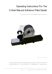
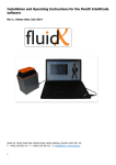
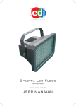
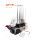
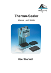
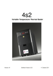
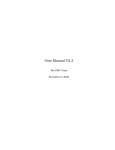
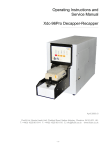
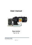
Operating Instructions For The X-Seal Manual Thermal Sealer __________________________________ Version 1 Release 1 May 2009 ©FluidX Ltd. FluidX Ltd. Monks Heath Hall, Chelford Road, Nether Alderley, Cheshire, SK10 4SY, UK. T: +44(0) 1625 861 614 F: +44(0) 1625 861 615 E: [email protected] www.fluidx.co.uk Page 1 of 16 Operating Instructions For The X-Seal Manual Thermal Sealer This document is for information only; the manufacturer accepts no liability for errors contained herein or for incidental or consequential damages with the furnishing, performance, or use of this material. Unless otherwise specified references to names or parts is purely casual and has the purpose of illustrating the product. The contents of this publication may not be reproduced in any form or by any means (including electronic storage and retrieval or translation into a foreign language) without prior agreement and written consent from the copyright owner. The information contained in this document is subject to change without notice. All rights reserved. Page 2 of 16 Operating Instructions For The X-Seal Manual Thermal Sealer Page 3 of 16 Operating Instructions For The X-Seal Manual Thermal Sealer TABLE OF CONTENTS 1. INTRODUCTION 5 1.1 5 Sealing process overview 2. WARNINGS 6 3. APPLICABLE RULES 7 4. TECHNICAL SPECIFICATIONS 7 5.1 Set Up Parameters 7 GENERAL DESCRIPTION 8 5.1 Main components 8 5.2 Control panel 8 5.3 Rear power interface 9 5. 6. 7. 8. 9. 10. INSTALLATION 9 6.1 Set up before use 9 6.2 To check voltage and change 10 6.3 Setting sealing temperature and time 11 6.4 To set audible warning for stand-by and power down 11 BASIC FUNCTIONS 12 7.1 Run cycle 12 7.2 Stand-by cycle 12 7.3 Power-down cycle 12 7.4 Locking the drawer 13 TROUBLE SHOOTING 13 8.1 Introduction 13 8.2 Errors 13 8.2 Sealing film inserted upside down 14 MAINTENANCE 15 9.1 15 Routine maintenance ACCESSORIES AND CONSUMABLES 15 10.1 Plate and seal compatibility 15 10.1 Sealing examples 16 Page 4 of 16 Operating Instructions For The X-Seal Manual Thermal Sealer 1. INTRODUCTION The X-Seal Manual Thermal Sealer is designed to seal a wide variety of sample plates in a controlled, safe manner. Both sealing time and temperature are programmable and a visual countdown is displayed during the sealing process. The Manaual Thermal Sealer can be used with most microplates and sealing films to prevent sample loss during exposure to high temperatures or for long-term storage. Temperature and seal time for a specific sealing operation can be preset by the user and adapted according to the type of plate and seal to be used. 1.1 Sealing process overview Fig. 1. The X-Seal Manual Thermal Sealer is simple to use (see Fig 1. for overview). After selecting the sealing time and temperature as required, the drawer is opened and the plate is placed on the holder. The seal is the positioned on top (with a brass holding plate on top to prevent curling if desired) and the sealing process starts automatically once the drawer is closed. The plate and seal are brought into contact with the internal heating plate. The display shows the amount of sealing time remaining. When zero is reached the drawer will open and the sealed plate will be returned to the original position, ready for the user to remove. Page 5 of 16 Operating Instructions For The X-Seal Manual Thermal Sealer 2. WARNINGS Please read the following before attempting to use the Manual Thermal Sealer. WARNING. Refer to manual The Manual Thermal Sealer is designed for indoor laboratory use only. Altitude Temperature range Relative humidity Less than 2200m above sea level 15°C to 35°C 5% to 85% non-condensing. If the instrument is stored outside of these ranges then it should be allowed to equilibrate before use. Ensure that the correct voltage is selected and appropriate fuse fitted. Do not work outside the rated power supply range. Use the cleaning method recommended by the manufacturer. Ensure the unit is connected to an earthed supply. Do not remove the outer housing. The Manual thermal Sealer should only be serviced or repaired by an appropriately trained technician. WARNING. Hot surface The internal heating plate is capable of reaching 200°C. Serious injury may occur if touched. The sealer will remain hot for a significant amount of time after use. Ensure the unit is cold before cleaning. Foil-sealed plates can remain hot after sealing and should be handled with care. WARNING. Risk of electric shock, high voltage. This equipment should only be dismantled by properly trained personnel. Removing the casing will expose potentially lethal voltages. Page 6 of 16 Operating Instructions For The X-Seal Manual Thermal Sealer 3. APPLICABLE RULES 2006/95/CE 2004/108/CE 2002/96/CE 4. Low Voltage Directive Electromagnetic Compatibility Directive amended 2003/108/CE WEEE Directive TECHNICAL SPECIFICATIONS Dimensions 310mm x 275mm x 181mm (H x W x D) Weight 9kg Voltage 230/115/100 ±10% Vac 47/63 Hz Power 300 W Temperature range Operative: 18°C - 35°C Storage: -20°C - 40°C Relative humidity 20% - 80% not condensing Table 1 5.1 Set Up Parameters Sealing temperature OFF or from 120°C to 180°C Step: 1°C Default: off Sealing time From 0.0 to 10 seconds Step: 0.5 secs Default: 3 secs Stand-by cycle “no” stand-by, or from 1 to 99 minutes Step: 1 min Default: 60 min Stand-by temperature: 60°C, not programmable Power down time From 1 to 24 hours Step: 1 hour Default: 10 hours Power down temperature: ambient Warning (acoustic) buzzer On/off Default: on Table 2 Page 7 of 16 Operating Instructions For The X-Seal Manual Thermal Sealer 5. GENERAL DESCRIPTION 5.1 Main components Fig. 2. The Manual Thermal Sealer (see Fig. 2.) comprises of: Cabinet Control panel Rear Power Interface Electronic circuit Heating plate Handling system (motor, handler, sensors) Plate carrier (optional) Brass plate (optional) to avoid seal curling during sealing process. 5.2 Control panel Fig. 3. The control panel (see Fig. 3.) contains: Amber LED status indicator (1), this will blink while the sealer is warming up. The blinking will end when the desired temperature has been reached. Set-up/Run mode selection key (2) LED status display (3). Directional keys, up and down (4 and 5). Page 8 of 16 Operating Instructions For The X-Seal Manual Thermal Sealer 5.3 Rear power interface Fig. 4. The rear power interface (see Fig. 4.) contains: Power setting (115/230 Vac) and fuse holder (1) Power switch (2) Mains power supply socket (3). 6. INSTALLATION 6.1 Set up before use Remove the sealer from its packaging. All packaging and fixtures should be saved as the sealer must be transported in the original packaging to avoid damage. Place the sealer on a level surface, away from direct sunlight. Ensure access to the power switch at the back of the sealer is maintaine. Do not obstruct vents. Check the correct voltage had been selected using the switch at the back of the sealer (see section 6.2). Connect the sealer to the mains power supply and switch on (using the I/O switch at the rear). A blinking amber LED will be displayed on the control panel to confirm that power is being supplied to the sealer. The blinking will stop when the set temperature has been reached and the sealer is ready for use. Page 9 of 16 Operating Instructions For The X-Seal Manual Thermal Sealer 6.2 To check voltage and change WARNING: Ensure that the sealer is not connected to the mains power at this time. At the rear of the sealer is a connection panel with the following: Power setting (230/115 Vac) and fuse holder On/off Power Switch Mains supply plug socket. The voltage setting is written in white, on a red background, on the top of power setting and fuse holder. The factory setting is 230V. Fig. 5a. Fig. 5b. To change the voltage setting: Open fuse holder compartment with a screwdriver, (Fig. 5a). Then, using the screwdriver, extract the fuse holder, (Fig. 5b). Replace the two fuses as indicated in table 3 below. Power Voltage Fuse (EN 60127) 115v 3.15A (T) 230v 2A (T) Table 3 Insert the fuse holder and keep the set voltage label placed at the top. Close the fuse compartment, pressing gently. If the fuse is correctly inserted the voltage selected should be visible. Page 10 of 16 Operating Instructions For The X-Seal Manual Thermal Sealer 6.3 Setting sealing temperature and time Turn on the sealer. To enter the Set-up mode, press and release the “M” key. The display will flash the last sealing temperature. The temperature can be decreased or increased using the keys. Press the “M” key gain to store the new temperature value. The sealing time can now be selected. The display will show a flashing “t” and the previous sealing time. The sealing time can be decreased or increased with the keys. (Range is between 0.0 and 10 seconds with steps of 0.5 second). Press the “M” key to store the new sealing time and exit from the set-up menu. The sealer will return to “run cycle” mode. 6.4 To set audible warning for stand-by and power down To set an audible indicator for stand-by and power-down press the “M” key for 10 seconds and release. The display will show a flashing “L” and the last stand-by time set. The stand-by time is the amount of time the sealer is left unused before the temperature is automatically reduced to 60°C. This stand-by time is selected by using the keys. (Range from 1 to 99 minutes, with steps of 1 minute). The new stand-by time value is stored by pressing “M” key again. The power-down time can then be set. The display shows a flashing “P” and the last set power-down time. The power-down time is the amount of time the sealer is left unused before the heating plate is automatically switched off. The power-down time is selected using the keys. ( Range between 1 and 24 hours with steps of 1 hour). The new power-down time value is stored by pressing the “M” key again. It is then possible to set the audible warning (buzzer). The display shows a flashing “S” and the last set buzzer function. The buzzer function is enabled (“on”) or disabled ( “no”) using the keys. Press the “M” key to store the audible warning settings. The sealer will then return to the “run cycle”. Page 11 of 16 Operating Instructions For The X-Seal Manual Thermal Sealer 7. BASIC FUNCTIONS 7.1 Run cycle Turn the sealer on. The sealer will go to the home position: The “open drawer sensor” and the “low handler sensor” become active The “high handler sensor” becomes inactive. The heating plate becomes warm. The increasing temperature is displayed and the amber LED will flash. When the heating plate reaches the set temperature an audible warning will be heard and the amber LED will stop flashing. The sealer is ready for use. Load the plate onto the plate carrier. Place the sealing film over the plate, ensuring that the sealing surface is face down and close the drawer. The sealing film and plate are automatically placed in contact with the heating plate. The display shows “t” and the remaining sealing time is shown. An audible warning is given when the timer reachs zero. The sealer returns the plate to the home position and the drawer is released. The user is then able to remove the sealed plate a new cycle can be started. NOTE: Plates sealed with a foil backed film may remain hot for a number of seconds after sealing. Care should be taken in handling. 7.2 Stand-by cycle If the sealer remains in ready mode for the amount of time set as Stand-by time then the temperature of the heating plate will reduce to 60°C. The display will indicate a decrease in temperature and the amber LED will be off. The temperature of the heating plate will be maintained at 60°C with a +/- 3°C precision. The display will show the exact temperature of the heating plate. The run cycle can be restarted by pressing any key. 7.3 Power-down cycle If the sealer remains inactive (and on stand-by) for the set power-down time then the heating plate will turn off. The amber light will be off and the display will show a decreasing temperature until 45°C is reached, then “LO” is displayed. Press any key to restart the run cycle. Page 12 of 16 Operating Instructions For The X-Seal Manual Thermal Sealer 7.4 Locking the drawer It is possible to lock the drawer when the sealer is not used to prevent dust contaminating the internal parts of the unit: Press the key and hold down while closing the drawer. The drawer is then locked automatically. Turn off the power. To unlock simply turn power on. 8. TROUBLE SHOOTING 8.1 Introduction A list of possible errors are summerised in this section, if the solutions offered are unsuccessful please contact your supplier. 8.2 Errors If errors occur an intermittent audible warning sound is heard and the display will indicate the error type (see Table 4). Er1 The sealer is not able to reach home position in the time defined. Er2 The system does not remain in the increase band Er3 The plate will not reach the “high handler sensor” within a defined time. Er4 The plate will not reach the “low handler sensor” within a defined time. Er5 Motor over current Er6 Temperature sensor has been opened or disconnected. Er7 “open drawer sensor” active during upwards movement Er8 “low handler sensor” active during upward movement. Table 4 These errors will be shown on the display until the problem is resolved. To clear “h” error, retry the operation that generated the error. If an error is not resolved within 10 seconds the heating plate is automatically turned off to avoid sample damage. To restart, turn the power off, resolve the problem and turn power back on. If the error is resolved within the 10 second limit the sealer will return to the “run cycle”. Page 13 of 16 Operating Instructions For The X-Seal Manual Thermal Sealer 8.2 Sealing film inserted upside down A seal can become stuck on the heating plate if the seal is placed upside down on the plate To clean the heating plate: Turn the sealer off and disconnect from the mains power supply. Do not attempt to clean the unit until it has thoroughly cooled. Remove the screw on the back of the sealer (see Fig. 6), turn anti-clockwise. Fig. 6. Remove the drawer (see Fig. 7). Clean the heating plate with a dry duster to remove the sealing film residue. Replace the drawer. Lock the screw clockwise on the reverse of the sealer (see Fig. 8) and turn the sealer on. Fig. 7. Fig. 8. Page 14 of 16 Operating Instructions For The X-Seal Manual Thermal Sealer 9. MAINTENANCE 9.1 Routine maintenance The sealer requires just cleaning on a routine basis, using a cloth dipped in water or ethanol, methanol. Formaldehyde can also be used. NOTE: The sealer should not be immersed in solvents. Do not use acetone or abrasive cleaners. Do not autoclave any parts. If radio-active spillages occur, use an appropriate cleaning agent. Any cleaning procedure should be performed with the sealer turned off, the power cable disconnected and with the parts at ambient temperature. If any additional maintenance is required, please contact your supplier for assistance. 10. ACCESSORIES AND CONSUMABLES 10.1 Plate and seal compatibility The X-Seal Manual Thermal Sealer is compatible with the following consumables: Polypropylene, polyethylene and polystyrene plates SBS format shallow well plates. Deep well plates. Tube blocks. PCR plates. Thermal seals Foil polypropylene laminate. Clear polyester polypropylene laminate. Clear polymer. Thin clear polymer. Foil laminate. Foil. Plate carrier A plate carrier is required when using the Manual Thermal Sealer with PCR plates. Page 15 of 16 Operating Instructions For The X-Seal Manual Thermal Sealer 10.1 Sealing examples Fig. 9. Peelable seal Fig. 10. Pierceable seal Fig. 11. Using brass seal holder to prevent seal curling upwards. Manufactured for: Manufactured by: fluidX Ltd. Monks Heath Hall Helford Road Nether Alderley Cheshire SK10 4SY UK HTA Srl Via del Mella, 77/79 Brescia I-25131 Italy Tel: +39 (0) 030 3582920 Fax: +39 (0) 030 3582930 www.hta-it.com Tel: +44 (0) 1625 861 614 Fax: +44 (0) 1625 861 615 Email: [email protected] www.fluidx.co.uk Page 16 of 16 Operating Instructions For The X-Seal Manual Thermal Sealer