1
Connection Manual
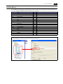
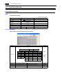
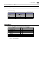
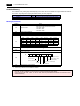
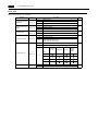
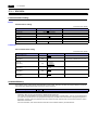
Record of Revisions
Reference numbers are shown at the bottom left corner on the back cover of each manual.
Printing Date
Reference No.
Revised Contents
July, 2009
2202NE0
First edition
December. 2009
2202NE1
Second edition
April. 2013
2202NE2
Third edition
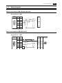
• LS XGT/XGK series CPU Wiring diagram
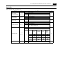
Preface
Thank you for selecting the MONITOUCH S8 series.
For correct set-up of the S8 series, you are requested to read through this manual to understand more about the product.
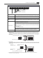
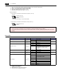
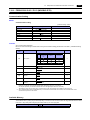
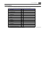
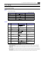
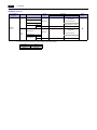
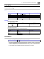
For more information about the S8 series, refer to the following related manuals.
Manual Name
Contents
Reference No.
S8 series Reference Manual
The functions and instructions of the S8 series are explained.
1201NE
V Series Macro Reference
An overview of macros of V-SFT version 5 as well as macro editor
operations and macro command description are explained.
1056NE
V8 Series Operation Manual
The information related to the operations of V-SFT version 5, such as
software composition, editing procedure or limitations, is explained in detail.
1058NE
S8 Series Hardware Specifications
Notes on usage and hardware specifications for the S8 series are explained.
2020NE
For further details about PLCs, inverters, or temperature controllers, refer to the manual attached to each controller.
Notes:
1. This manual may not, in whole or in part, be printed or reproduced without the prior written consent of Hakko Electronics
Co., Ltd.
2. The information in this manual is subject to change without prior notice.
3. Windows and Excel are registered trademarks of Microsoft Corporation in the United States and other countries.
4. All other company names or product names are trademarks or registered trademarks of their respective holders.
5. This manual is intended to give accurate information about MONITOUCH hardware. If you have any questions, please
contact your local distributor.
Notes on Safe Usage of MONITOUCH
In this manual, you will find various notes categorized under the following two levels with the signal words “Danger” and “Caution”.
DANGER
Indicates an imminently hazardous situation which, if not avoided, will result in death or serious injury.
CAUTION
Indicates a potentially hazardous situation which, if not avoided, may result in minor or moderate injury and
could cause property damage.
Note that there is a possibility that the item listed with
CAUTION may have serious ramifications.
DANGER
• Never use the output signal of MONITOUCH for operations that may threaten human life or damage the system, such as signals
used in case of emergency. Please design the system so that it can cope with the malfunctions of a touch switch. A malfunction of
a touch switch will result in machine accident or damage.
• Turn off the power supply when you set up the unit, connect new cables, or perform maintenance or inspections. Otherwise,
electrical shock or damage may occur.
• Never touch any terminals while the power is on. Otherwise, electric shock may occur.
• You must put a cover on the terminals on the unit when you turn the power on and operate the unit. Without the terminal cover in
place, electric shock may occur.
• The liquid crystal in the LCD panel is a hazardous substance. If the LCD panel is damaged, do not ingest the leaked liquid crystal.
If the liquid crystal spills on skin or clothing, use soap and wash off thoroughly.
• Never disassemble, recharge, deform by pressure, short-circuit, reverse the polarity of the lithium battery, nor dispose of the lithium
battery in fire. Failure to follow these conditions will lead to explosion or ignition.
• Never use a lithium battery that is deformed, leaks, or shows any other signs of abnormality. Failure to follow these conditions will
lead to explosion or fire.
CAUTION
• Check the appearance of MONITOUCH when it is unpacked. Do not use the unit if any damage or deformation is found. Failure to
do so may lead to fire, damage or malfunction.
• For use in a facility or for a system related to nuclear energy, aerospace, medical, traffic equipment, or mobile installations, please
consult your local distributor.
• Operate (or store) MONITOUCH under the conditions indicated in this manual and related manuals. Failure to do so could cause
fire, malfunction, physical damage or deterioration.
• Understand the following environmental limits for use and storage of MONITOUCH. Otherwise, fire or damage to the unit may
result.
- Avoid locations where there is a possibility that water, corrosive gas, flammable gas, solvents, grinding fluids or cutting oil can
come into contact with the unit.
- Avoid high temperature, high humidity, and outside weather conditions, such as wind, rain or direct sunlight.
- Avoid locations where excessive dust, salt, and metallic particles are present.
- Avoid installing the unit in a location where vibration or physical shock may be transmitted.
• Equipment must be correctly mounted so that the main terminal of MONITOUCH will not be touched inadvertently. Otherwise, an
accident or electric shock may occur.
• Tighten the fixtures of MONITOUCH with a torque in the specified range. Excessive tightening may distort the panel surface.
Loose tightening may cause MONITOUCH to come off, malfunction or be short-circuited.
• Tighten terminal screws on the power supply terminal block equally with a torque in the specified range. Improper tightening of
screws may result in fire, malfunction, or trouble, so check periodically that terminal screws on the power supply terminal block and
fixtures are firmly tightened.
• MONITOUCH has a glass screen. Do not drop or give physical shock to the unit. Otherwise, the screen may be damaged.
• Connect the cables correctly to the terminals of MONITOUCH in accordance with the specified voltage and wattage. Over-voltage,
over-wattage, or incorrect cable connection could cause fire, malfunction or damage to the unit.
• Be sure to establish a ground of MONITOUCH. Ground FG terminal which must be used for the unit. Otherwise, electric shock or
a fire may occur.
• Prevent any conductive particles from entering into MONITOUCH. Failure to do so may lead to fire, damage, or malfunction.
• Do not attempt to repair MONITOUCH at your site. Ask Hakko Electronics or the designated contractor for repair.
• Do not repair, disassemble or modify MONITOUCH. Hakko Electronics Co., Ltd. is not responsible for any damages resulting from
repair, disassembly or modification of MONITOUCH that was performed by an unauthorized person.
• Do not use a sharp-pointed tool when pressing a touch switch. Doing so may damage the display unit.
• Only experts are authorized to set up the unit, connect the cables or perform maintenance and inspection.
• Lithium batteries contain combustible material such as lithium or organic solvent. Mishandling may cause heat, explosion or
ignition resulting in fire or injury. Read related manuals carefully and handle the lithium battery correctly as instructed.
• Do not press two or more points on the screen at the same time. If two or more positions are pressed at the same time, the switch
located between the pressed positions activates.
CAUTION
• Take safety precautions during such operations as setting change during running, forced output, start, and stop. Any misoperation
may cause unexpected machine motions, resulting in machine accident or damage.
• In facilities where a failure of MONITOUCH could lead to accident threatening human life or other serious damage, be sure that the
facilities are equipped with adequate safeguards.
• At the time of disposal, MONITOUCH must be treated as industrial waste.
• Before touching MONITOUCH, discharge static electricity from your body by touching grounded metal. Excessive static electricity
may cause malfunction or trouble.
[General Notes]
• Never bundle control cables nor input/output cables with high-voltage and large-current carrying cables such as power supply cables.
Keep these cables at least 200 mm away from the high-voltage and large-current carrying cables. Otherwise, malfunction may occur
due to noise.
• When using MONITOUCH in an environment where a source of high-frequency noise is present, it is recommended that the FG
shielded cable (communication cable) be grounded at its ends. However, the cable may be grounded only at one end if this is
necessary due to unstable communication conditions or for any other reason.
• Plug connectors or sockets of MONITOUCH in the correct orientation. Failure to do so may lead to malfunction.
• Do not use thinners for cleaning because they may discolor the MONITOUCH surface. Use alcohol or benzine commercially
available.
• If a data receive error occurs when MONITOUCH and the counterpart (PLC, temperature controller, etc.) are started at the same
time, read the manual for the counterpart unit and remove the error correctly.
• Avoid discharging static electricity on the mounting panel of MONITOUCH. Static charges can damage the unit and cause
malfunctions. Otherwise, malfunction may occur due to noise.
• Avoid prolonged display of any fixed pattern. Due to the characteristics of the liquid crystal display, an afterimage may occur. If a
prolonged display of a fixed pattern is expected, use the auto OFF function of the backlight.
[General Notes]
Note that the following conditions may occur under normal circumstances.
• The response time, brightness and colors of the S8 series may be affected by the ambient temperature.
• Tiny spots (dark or luminescent) may appear on the display due to the liquid crystal characteristics.
• There are variations in brightness and colors on each unit.
• Cold cathode tubes are incorporated into the S808’s LCD display for backlights. Optical properties (brightness, irregular colors, etc.)
may change in a low-temperature environment or over time of operation.
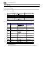
Contents
1.
Overview
1.1
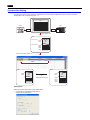
2-way Communication . . . . . . . . . . . . . . . . . . . . . . . . . . . . . . . . . . . . . . . . . . . . . . . . . . . . . . . 1-1
1.1.1
1.2
Connection Modes . . . . . . . . . . . . . . . . . . . . . . . . . . . . . . . . . . . . . . . . . . . . . . . . . . . . . . . . . . 1-2
1.2.1
1.2.2
1.2.3
1.2.4
1.3
PLC1 to PLC2. . . . . . . . . . . . . . . . . . . . . . . . . . . . . . . . . . . . . . . . . . . . . . . . . . . . . . . . . . . . . . . . . . . . . . . 1-13
Read/Write Area . . . . . . . . . . . . . . . . . . . . . . . . . . . . . . . . . . . . . . . . . . . . . . . . . . . . . . . . . . . . . . . . . . . . . 1-16
Others . . . . . . . . . . . . . . . . . . . . . . . . . . . . . . . . . . . . . . . . . . . . . . . . . . . . . . . . . . . . . . . . . . . . . . . . . . . . . 1-23
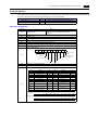
ALLEN BRADLEY
2.1
PLC Connection . . . . . . . . . . . . . . . . . . . . . . . . . . . . . . . . . . . . . . . . . . . . . . . . . . . . . . . . . . . . 2-1
2.1.1
2.1.2
2.1.3
2.1.4
3.
COM1 (RS-422/485) Connection . . . . . . . . . . . . . . . . . . . . . . . . . . . . . . . . . . . . . . . . . . . . . . . . . . . . . . . . 1-10
COM2 (RS-232C) Connection . . . . . . . . . . . . . . . . . . . . . . . . . . . . . . . . . . . . . . . . . . . . . . . . . . . . . . . . . . 1-12
Settings for the Connected Device . . . . . . . . . . . . . . . . . . . . . . . . . . . . . . . . . . . . . . . . . . . . . 1-13
1.5.1
1.5.2
1.5.3
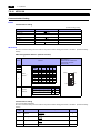
2.
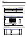
COM1 . . . . . . . . . . . . . . . . . . . . . . . . . . . . . . . . . . . . . . . . . . . . . . . . . . . . . . . . . . . . . . . . . . . . . . . . . . . . . . 1-8
COM2 . . . . . . . . . . . . . . . . . . . . . . . . . . . . . . . . . . . . . . . . . . . . . . . . . . . . . . . . . . . . . . . . . . . . . . . . . . . . . . 1-9
Wiring . . . . . . . . . . . . . . . . . . . . . . . . . . . . . . . . . . . . . . . . . . . . . . . . . . . . . . . . . . . . . . . . . . . 1-10
1.4.1
1.4.2
1.5
PLC Connection . . . . . . . . . . . . . . . . . . . . . . . . . . . . . . . . . . . . . . . . . . . . . . . . . . . . . . . . . . . . . . . . . . . . . . 1-2
1 : 1 Connection . . . . . . . . . . . . . . . . . . . . . . . . . . . . . . . . . . . . . . . . . . . . . . . . . . . . . . . . . . . . . . . . . . . . . . 1-2
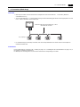
1 : n Connection (Multi-drop) . . . . . . . . . . . . . . . . . . . . . . . . . . . . . . . . . . . . . . . . . . . . . . . . . . . . . . . . . . . . 1-3
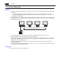
n : 1 Connection (Multi-link2) . . . . . . . . . . . . . . . . . . . . . . . . . . . . . . . . . . . . . . . . . . . . . . . . . . . . . . . . . . . . 1-4
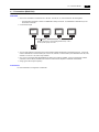
n : 1 Connection (Multi-link) . . . . . . . . . . . . . . . . . . . . . . . . . . . . . . . . . . . . . . . . . . . . . . . . . . . . . . . . . . . . . 1-5
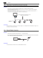
Temperature Controller/Servo/Inverter Connection . . . . . . . . . . . . . . . . . . . . . . . . . . . . . . . . . . . . . . . . . . . 1-6
Barcode Reader Connection . . . . . . . . . . . . . . . . . . . . . . . . . . . . . . . . . . . . . . . . . . . . . . . . . . . . . . . . . . . . 1-6
Slave Communication. . . . . . . . . . . . . . . . . . . . . . . . . . . . . . . . . . . . . . . . . . . . . . . . . . . . . . . . . . . . . . . . . . 1-7
V-Link . . . . . . . . . . . . . . . . . . . . . . . . . . . . . . . . . . . . . . . . . . . . . . . . . . . . . . . . . . . . . . . . . . . . . . . . . . . . . . 1-7
Modbus RTU. . . . . . . . . . . . . . . . . . . . . . . . . . . . . . . . . . . . . . . . . . . . . . . . . . . . . . . . . . . . . . . . . . . . . . . . . 1-7
Physical Port. . . . . . . . . . . . . . . . . . . . . . . . . . . . . . . . . . . . . . . . . . . . . . . . . . . . . . . . . . . . . . . 1-8
1.3.1
1.3.2
1.4
Overview. . . . . . . . . . . . . . . . . . . . . . . . . . . . . . . . . . . . . . . . . . . . . . . . . . . . . . . . . . . . . . . . . . . . . . . . . . . . 1-1
Serial Connection . . . . . . . . . . . . . . . . . . . . . . . . . . . . . . . . . . . . . . . . . . . . . . . . . . . . . . . . . . . . . . . . . . . . . 2-1
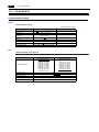
Control Logix / Compact Logix . . . . . . . . . . . . . . . . . . . . . . . . . . . . . . . . . . . . . . . . . . . . . . . . . . . . . . . . . . . 2-2
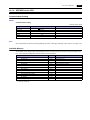
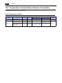
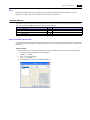
Communication Setting. . . . . . . . . . . . . . . . . . . . . . . . . . . . . . . . . . . . . . . . . . . . . . . . . . . . . . . . . . . . . . . . . 2-2
Available Memory . . . . . . . . . . . . . . . . . . . . . . . . . . . . . . . . . . . . . . . . . . . . . . . . . . . . . . . . . . . . . . . . . . . . . 2-4
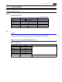
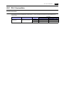
SLC500. . . . . . . . . . . . . . . . . . . . . . . . . . . . . . . . . . . . . . . . . . . . . . . . . . . . . . . . . . . . . . . . . . . . . . . . . . . . . 2-5
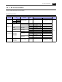
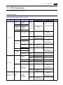
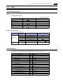
Communication Setting. . . . . . . . . . . . . . . . . . . . . . . . . . . . . . . . . . . . . . . . . . . . . . . . . . . . . . . . . . . . . . . . . 2-5
Available Memory . . . . . . . . . . . . . . . . . . . . . . . . . . . . . . . . . . . . . . . . . . . . . . . . . . . . . . . . . . . . . . . . . . . . . 2-7
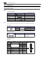
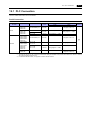
Micro Logix . . . . . . . . . . . . . . . . . . . . . . . . . . . . . . . . . . . . . . . . . . . . . . . . . . . . . . . . . . . . . . . . . . . . . . . . . . 2-8
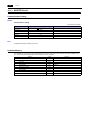
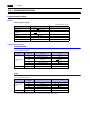
Communication Setting. . . . . . . . . . . . . . . . . . . . . . . . . . . . . . . . . . . . . . . . . . . . . . . . . . . . . . . . . . . . . . . . . 2-8
Available Memory . . . . . . . . . . . . . . . . . . . . . . . . . . . . . . . . . . . . . . . . . . . . . . . . . . . . . . . . . . . . . . . . . . . . . 2-9
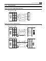
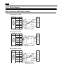
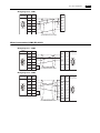
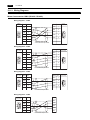
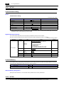
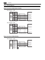
Wiring Diagrams . . . . . . . . . . . . . . . . . . . . . . . . . . . . . . . . . . . . . . . . . . . . . . . . . . . . . . . . . . . . . . . . . . . . . 2-10
When Connected at COM1 (RS-422 / RS-485):. . . . . . . . . . . . . . . . . . . . . . . . . . . . . . . . . . . . . . . . . . . . . 2-10
When Connected at COM2 (RS-232C): . . . . . . . . . . . . . . . . . . . . . . . . . . . . . . . . . . . . . . . . . . . . . . . . . . . 2-10
Automation Direct
3.1
PLC Connection . . . . . . . . . . . . . . . . . . . . . . . . . . . . . . . . . . . . . . . . . . . . . . . . . . . . . . . . . . . . 3-1
3.1.1
3.1.2
3.1.3
Serial Connection . . . . . . . . . . . . . . . . . . . . . . . . . . . . . . . . . . . . . . . . . . . . . . . . . . . . . . . . . . . . . . . . . . . . . 3-1
Direct LOGIC (K-Sequence) . . . . . . . . . . . . . . . . . . . . . . . . . . . . . . . . . . . . . . . . . . . . . . . . . . . . . . . . . . . . . 3-2
Communication Setting. . . . . . . . . . . . . . . . . . . . . . . . . . . . . . . . . . . . . . . . . . . . . . . . . . . . . . . . . . . . . . . . . 3-2
Available Memory . . . . . . . . . . . . . . . . . . . . . . . . . . . . . . . . . . . . . . . . . . . . . . . . . . . . . . . . . . . . . . . . . . . . . 3-4
Direct LOGIC (MODBUS RTU). . . . . . . . . . . . . . . . . . . . . . . . . . . . . . . . . . . . . . . . . . . . . . . . . . . . . . . . . . . 3-5
Communication Setting. . . . . . . . . . . . . . . . . . . . . . . . . . . . . . . . . . . . . . . . . . . . . . . . . . . . . . . . . . . . . . . . . 3-5
Available Memory . . . . . . . . . . . . . . . . . . . . . . . . . . . . . . . . . . . . . . . . . . . . . . . . . . . . . . . . . . . . . . . . . . . . . 3-6
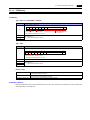
Wiring Diagrams . . . . . . . . . . . . . . . . . . . . . . . . . . . . . . . . . . . . . . . . . . . . . . . . . . . . . . . . . . . . . . . . . . . . . . 3-7
When Connected at COM1 (RS-422 / RS-485):. . . . . . . . . . . . . . . . . . . . . . . . . . . . . . . . . . . . . . . . . . . . . . 3-7
When Connected at COM2 (RS-232C): . . . . . . . . . . . . . . . . . . . . . . . . . . . . . . . . . . . . . . . . . . . . . . . . . . . . 3-8
4.
EATON Cutler-Hammer
4.1
PLC Connection . . . . . . . . . . . . . . . . . . . . . . . . . . . . . . . . . . . . . . . . . . . . . . . . . . . . . . . . . . . . 4-1
4.1.1
4.1.2
5.
PLC Connection . . . . . . . . . . . . . . . . . . . . . . . . . . . . . . . . . . . . . . . . . . . . . . . . . . . . . . . . . . . . 5-1
5.1.1
5.1.2
Serial Connection. . . . . . . . . . . . . . . . . . . . . . . . . . . . . . . . . . . . . . . . . . . . . . . . . . . . . . . . . . . . . . . . . . . . .
Power Mate . . . . . . . . . . . . . . . . . . . . . . . . . . . . . . . . . . . . . . . . . . . . . . . . . . . . . . . . . . . . . . . . . . . . . . . . .
Communication Setting . . . . . . . . . . . . . . . . . . . . . . . . . . . . . . . . . . . . . . . . . . . . . . . . . . . . . . . . . . . . . . . .
Available Memory . . . . . . . . . . . . . . . . . . . . . . . . . . . . . . . . . . . . . . . . . . . . . . . . . . . . . . . . . . . . . . . . . . . .
Wiring Diagrams . . . . . . . . . . . . . . . . . . . . . . . . . . . . . . . . . . . . . . . . . . . . . . . . . . . . . . . . . . . . . . . . . . . . .
When Connected at COM1 (RS-422 / RS-485): . . . . . . . . . . . . . . . . . . . . . . . . . . . . . . . . . . . . . . . . . . . . .
When Connected at COM2 (RS-232C):. . . . . . . . . . . . . . . . . . . . . . . . . . . . . . . . . . . . . . . . . . . . . . . . . . . .
5-1
5-2
5-2
5-2
5-3
5-3
5-4
FATEK AUTOMATION
6.1
PLC Connection . . . . . . . . . . . . . . . . . . . . . . . . . . . . . . . . . . . . . . . . . . . . . . . . . . . . . . . . . . . . 6-1
6.1.1
6.1.2
7.
4-1
4-2
4-2
4-2
4-3
4-3
4-3
FANUC
5.1
6.
Serial Connection. . . . . . . . . . . . . . . . . . . . . . . . . . . . . . . . . . . . . . . . . . . . . . . . . . . . . . . . . . . . . . . . . . . . .
ELC . . . . . . . . . . . . . . . . . . . . . . . . . . . . . . . . . . . . . . . . . . . . . . . . . . . . . . . . . . . . . . . . . . . . . . . . . . . . . . .
Communication Setting . . . . . . . . . . . . . . . . . . . . . . . . . . . . . . . . . . . . . . . . . . . . . . . . . . . . . . . . . . . . . . . .
Available Memory . . . . . . . . . . . . . . . . . . . . . . . . . . . . . . . . . . . . . . . . . . . . . . . . . . . . . . . . . . . . . . . . . . . .
Wiring Diagrams . . . . . . . . . . . . . . . . . . . . . . . . . . . . . . . . . . . . . . . . . . . . . . . . . . . . . . . . . . . . . . . . . . . . .
When Connected at COM1 (RS-422 / RS-485): . . . . . . . . . . . . . . . . . . . . . . . . . . . . . . . . . . . . . . . . . . . . .
When Connected at COM2 (RS-232C):. . . . . . . . . . . . . . . . . . . . . . . . . . . . . . . . . . . . . . . . . . . . . . . . . . . .
Serial Connection. . . . . . . . . . . . . . . . . . . . . . . . . . . . . . . . . . . . . . . . . . . . . . . . . . . . . . . . . . . . . . . . . . . . .
FACON FB series . . . . . . . . . . . . . . . . . . . . . . . . . . . . . . . . . . . . . . . . . . . . . . . . . . . . . . . . . . . . . . . . . . . .
Communication Setting . . . . . . . . . . . . . . . . . . . . . . . . . . . . . . . . . . . . . . . . . . . . . . . . . . . . . . . . . . . . . . . .
Available Memory . . . . . . . . . . . . . . . . . . . . . . . . . . . . . . . . . . . . . . . . . . . . . . . . . . . . . . . . . . . . . . . . . . . .
Wiring Diagrams . . . . . . . . . . . . . . . . . . . . . . . . . . . . . . . . . . . . . . . . . . . . . . . . . . . . . . . . . . . . . . . . . . . . .
When Connected at COM1 (RS-422 / RS-485): . . . . . . . . . . . . . . . . . . . . . . . . . . . . . . . . . . . . . . . . . . . . .
When Connected at COM2 (RS-232C):. . . . . . . . . . . . . . . . . . . . . . . . . . . . . . . . . . . . . . . . . . . . . . . . . . . .
6-1
6-2
6-2
6-2
6-3
6-3
6-4
Fuji Electric
7.1
PLC Connection . . . . . . . . . . . . . . . . . . . . . . . . . . . . . . . . . . . . . . . . . . . . . . . . . . . . . . . . . . . . 7-1
7.1.1
7.1.2
7.1.3
7.1.4
7.1.5
7.1.6
7.1.7
7.1.8
7.2
Serial Connection. . . . . . . . . . . . . . . . . . . . . . . . . . . . . . . . . . . . . . . . . . . . . . . . . . . . . . . . . . . . . . . . . . . . . 7-1
MICREX-SX Model Selection . . . . . . . . . . . . . . . . . . . . . . . . . . . . . . . . . . . . . . . . . . . . . . . . . . . . . . . . . . . 7-2
MICREX-F Series . . . . . . . . . . . . . . . . . . . . . . . . . . . . . . . . . . . . . . . . . . . . . . . . . . . . . . . . . . . . . . . . . . . . 7-3
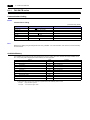
Communication Setting . . . . . . . . . . . . . . . . . . . . . . . . . . . . . . . . . . . . . . . . . . . . . . . . . . . . . . . . . . . . . . . . 7-3
Available Memory . . . . . . . . . . . . . . . . . . . . . . . . . . . . . . . . . . . . . . . . . . . . . . . . . . . . . . . . . . . . . . . . . . . . 7-5
SPB (N Mode) & FLEX-PC Series . . . . . . . . . . . . . . . . . . . . . . . . . . . . . . . . . . . . . . . . . . . . . . . . . . . . . . . . 7-6
Communication Setting . . . . . . . . . . . . . . . . . . . . . . . . . . . . . . . . . . . . . . . . . . . . . . . . . . . . . . . . . . . . . . . . 7-6
Available Memory . . . . . . . . . . . . . . . . . . . . . . . . . . . . . . . . . . . . . . . . . . . . . . . . . . . . . . . . . . . . . . . . . . . . 7-7
SPB (N Mode) & FLEX-PC CPU . . . . . . . . . . . . . . . . . . . . . . . . . . . . . . . . . . . . . . . . . . . . . . . . . . . . . . . . . 7-8
Communication Setting . . . . . . . . . . . . . . . . . . . . . . . . . . . . . . . . . . . . . . . . . . . . . . . . . . . . . . . . . . . . . . . . 7-8
Available Memory . . . . . . . . . . . . . . . . . . . . . . . . . . . . . . . . . . . . . . . . . . . . . . . . . . . . . . . . . . . . . . . . . . . . 7-8
MICREX-SX SPH/SPB Series (IEC Mode) . . . . . . . . . . . . . . . . . . . . . . . . . . . . . . . . . . . . . . . . . . . . . . . . . 7-9
Communication Setting . . . . . . . . . . . . . . . . . . . . . . . . . . . . . . . . . . . . . . . . . . . . . . . . . . . . . . . . . . . . . . . . 7-9
Available Memory . . . . . . . . . . . . . . . . . . . . . . . . . . . . . . . . . . . . . . . . . . . . . . . . . . . . . . . . . . . . . . . . . . . 7-10
MICREX-SX SPH/SPB Series (N Mode / F Mode) . . . . . . . . . . . . . . . . . . . . . . . . . . . . . . . . . . . . . . . . . . 7-11
Communication Setting . . . . . . . . . . . . . . . . . . . . . . . . . . . . . . . . . . . . . . . . . . . . . . . . . . . . . . . . . . . . . . . 7-11
Available Memory . . . . . . . . . . . . . . . . . . . . . . . . . . . . . . . . . . . . . . . . . . . . . . . . . . . . . . . . . . . . . . . . . . . 7-11
MICREX-SX SPH/SPB CPU (IEC Mode) . . . . . . . . . . . . . . . . . . . . . . . . . . . . . . . . . . . . . . . . . . . . . . . . . 7-11
Communication Setting . . . . . . . . . . . . . . . . . . . . . . . . . . . . . . . . . . . . . . . . . . . . . . . . . . . . . . . . . . . . . . . 7-11
Available Memory . . . . . . . . . . . . . . . . . . . . . . . . . . . . . . . . . . . . . . . . . . . . . . . . . . . . . . . . . . . . . . . . . . . 7-11
MICREX-SX SPH/SPB CPU (N Mode / F Mode). . . . . . . . . . . . . . . . . . . . . . . . . . . . . . . . . . . . . . . . . . . . 7-12
Communication Setting . . . . . . . . . . . . . . . . . . . . . . . . . . . . . . . . . . . . . . . . . . . . . . . . . . . . . . . . . . . . . . . 7-12
Available Memory . . . . . . . . . . . . . . . . . . . . . . . . . . . . . . . . . . . . . . . . . . . . . . . . . . . . . . . . . . . . . . . . . . . 7-12
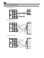
Wiring Diagrams . . . . . . . . . . . . . . . . . . . . . . . . . . . . . . . . . . . . . . . . . . . . . . . . . . . . . . . . . . . . . . . . . . . . 7-13
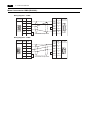
When Connected at COM1 (RS-422 / RS-485): . . . . . . . . . . . . . . . . . . . . . . . . . . . . . . . . . . . . . . . . . . . . 7-13
When Connected at COM2 (RS-232C):. . . . . . . . . . . . . . . . . . . . . . . . . . . . . . . . . . . . . . . . . . . . . . . . . . . 7-14
Temperature Controller/Servo/Inverter Connection . . . . . . . . . . . . . . . . . . . . . . . . . . . . . . . . 7-15
Temperature Controller . . . . . . . . . . . . . . . . . . . . . . . . . . . . . . . . . . . . . . . . . . . . . . . . . . . . . . . . . . . . . . .
Power Monitor Unit . . . . . . . . . . . . . . . . . . . . . . . . . . . . . . . . . . . . . . . . . . . . . . . . . . . . . . . . . . . . . . . . . .
Inverter. . . . . . . . . . . . . . . . . . . . . . . . . . . . . . . . . . . . . . . . . . . . . . . . . . . . . . . . . . . . . . . . . . . . . . . . . . . .
IH Inverter . . . . . . . . . . . . . . . . . . . . . . . . . . . . . . . . . . . . . . . . . . . . . . . . . . . . . . . . . . . . . . . . . . . . . . . . .
AC Power Monitor . . . . . . . . . . . . . . . . . . . . . . . . . . . . . . . . . . . . . . . . . . . . . . . . . . . . . . . . . . . . . . . . . . .
7-15
7-15
7-16
7-16
7-16
7.2.1
7.2.2
7.2.3
7.2.4
7.2.5
7.2.6
7.2.7
7.2.8
7.2.9
7.2.10
7.2.11
7.2.12
7.2.13
7.2.14
7.2.15
7.2.16
7.2.17
7.2.18
7.2.19
7.2.20
7.2.21
Servo Amplifier . . . . . . . . . . . . . . . . . . . . . . . . . . . . . . . . . . . . . . . . . . . . . . . . . . . . . . . . . . . . . . . . . . . . . . 7-16
Recorder . . . . . . . . . . . . . . . . . . . . . . . . . . . . . . . . . . . . . . . . . . . . . . . . . . . . . . . . . . . . . . . . . . . . . . . . . . . 7-17
Digital Panel Meter . . . . . . . . . . . . . . . . . . . . . . . . . . . . . . . . . . . . . . . . . . . . . . . . . . . . . . . . . . . . . . . . . . . 7-17
AC Power Regulator . . . . . . . . . . . . . . . . . . . . . . . . . . . . . . . . . . . . . . . . . . . . . . . . . . . . . . . . . . . . . . . . . . 7-17
Electronic Multimeter . . . . . . . . . . . . . . . . . . . . . . . . . . . . . . . . . . . . . . . . . . . . . . . . . . . . . . . . . . . . . . . . . 7-17
PYX (MODBUS RTU) . . . . . . . . . . . . . . . . . . . . . . . . . . . . . . . . . . . . . . . . . . . . . . . . . . . . . . . . . . . . . . . . . 7-18
Communication Setting. . . . . . . . . . . . . . . . . . . . . . . . . . . . . . . . . . . . . . . . . . . . . . . . . . . . . . . . . . . . . . . . 7-18
Available Memory . . . . . . . . . . . . . . . . . . . . . . . . . . . . . . . . . . . . . . . . . . . . . . . . . . . . . . . . . . . . . . . . . . . . 7-18
PXR (MODBUS RTU). . . . . . . . . . . . . . . . . . . . . . . . . . . . . . . . . . . . . . . . . . . . . . . . . . . . . . . . . . . . . . . . . 7-19
Communication Setting. . . . . . . . . . . . . . . . . . . . . . . . . . . . . . . . . . . . . . . . . . . . . . . . . . . . . . . . . . . . . . . . 7-19
Available Memory . . . . . . . . . . . . . . . . . . . . . . . . . . . . . . . . . . . . . . . . . . . . . . . . . . . . . . . . . . . . . . . . . . . . 7-19
PXG (MODBUS RTU). . . . . . . . . . . . . . . . . . . . . . . . . . . . . . . . . . . . . . . . . . . . . . . . . . . . . . . . . . . . . . . . . 7-20
Communication Setting. . . . . . . . . . . . . . . . . . . . . . . . . . . . . . . . . . . . . . . . . . . . . . . . . . . . . . . . . . . . . . . . 7-20
Available Memory . . . . . . . . . . . . . . . . . . . . . . . . . . . . . . . . . . . . . . . . . . . . . . . . . . . . . . . . . . . . . . . . . . . . 7-20
PXH (MODBUS RTU). . . . . . . . . . . . . . . . . . . . . . . . . . . . . . . . . . . . . . . . . . . . . . . . . . . . . . . . . . . . . . . . . 7-21
Communication Setting. . . . . . . . . . . . . . . . . . . . . . . . . . . . . . . . . . . . . . . . . . . . . . . . . . . . . . . . . . . . . . . . 7-21
Available Memory . . . . . . . . . . . . . . . . . . . . . . . . . . . . . . . . . . . . . . . . . . . . . . . . . . . . . . . . . . . . . . . . . . . . 7-21
PUM (MODBUS RTU) . . . . . . . . . . . . . . . . . . . . . . . . . . . . . . . . . . . . . . . . . . . . . . . . . . . . . . . . . . . . . . . . 7-22
Communication Setting. . . . . . . . . . . . . . . . . . . . . . . . . . . . . . . . . . . . . . . . . . . . . . . . . . . . . . . . . . . . . . . . 7-22
Available Memory . . . . . . . . . . . . . . . . . . . . . . . . . . . . . . . . . . . . . . . . . . . . . . . . . . . . . . . . . . . . . . . . . . . . 7-23
F-MPC04P (Loader) . . . . . . . . . . . . . . . . . . . . . . . . . . . . . . . . . . . . . . . . . . . . . . . . . . . . . . . . . . . . . . . . . . 7-24
Communication Setting. . . . . . . . . . . . . . . . . . . . . . . . . . . . . . . . . . . . . . . . . . . . . . . . . . . . . . . . . . . . . . . . 7-24
Available Memory . . . . . . . . . . . . . . . . . . . . . . . . . . . . . . . . . . . . . . . . . . . . . . . . . . . . . . . . . . . . . . . . . . . . 7-24
Station Number Table. . . . . . . . . . . . . . . . . . . . . . . . . . . . . . . . . . . . . . . . . . . . . . . . . . . . . . . . . . . . . . . . . 7-25
F-MPC Series / FePSU. . . . . . . . . . . . . . . . . . . . . . . . . . . . . . . . . . . . . . . . . . . . . . . . . . . . . . . . . . . . . . . . 7-28
Communication Setting. . . . . . . . . . . . . . . . . . . . . . . . . . . . . . . . . . . . . . . . . . . . . . . . . . . . . . . . . . . . . . . . 7-28
Available Memory . . . . . . . . . . . . . . . . . . . . . . . . . . . . . . . . . . . . . . . . . . . . . . . . . . . . . . . . . . . . . . . . . . . . 7-31
PLC_CTL . . . . . . . . . . . . . . . . . . . . . . . . . . . . . . . . . . . . . . . . . . . . . . . . . . . . . . . . . . . . . . . . . . . . . . . . . . 7-34
FVR-E11S (MODBUS RTU) . . . . . . . . . . . . . . . . . . . . . . . . . . . . . . . . . . . . . . . . . . . . . . . . . . . . . . . . . . . . 7-35
Communication Setting. . . . . . . . . . . . . . . . . . . . . . . . . . . . . . . . . . . . . . . . . . . . . . . . . . . . . . . . . . . . . . . . 7-35
Available Memory . . . . . . . . . . . . . . . . . . . . . . . . . . . . . . . . . . . . . . . . . . . . . . . . . . . . . . . . . . . . . . . . . . . . 7-35
FVR-C11S (MODBUS RTU) . . . . . . . . . . . . . . . . . . . . . . . . . . . . . . . . . . . . . . . . . . . . . . . . . . . . . . . . . . . . 7-36
Communication Setting. . . . . . . . . . . . . . . . . . . . . . . . . . . . . . . . . . . . . . . . . . . . . . . . . . . . . . . . . . . . . . . . 7-36
Available Memory . . . . . . . . . . . . . . . . . . . . . . . . . . . . . . . . . . . . . . . . . . . . . . . . . . . . . . . . . . . . . . . . . . . . 7-36
FRENIC5000 G11S / P11S (MODBUS RTU) . . . . . . . . . . . . . . . . . . . . . . . . . . . . . . . . . . . . . . . . . . . . . . . 7-37
Communication Setting. . . . . . . . . . . . . . . . . . . . . . . . . . . . . . . . . . . . . . . . . . . . . . . . . . . . . . . . . . . . . . . . 7-37
Available Memory . . . . . . . . . . . . . . . . . . . . . . . . . . . . . . . . . . . . . . . . . . . . . . . . . . . . . . . . . . . . . . . . . . . . 7-37
FRENIC5000 VG7S (MODBUS RTU) . . . . . . . . . . . . . . . . . . . . . . . . . . . . . . . . . . . . . . . . . . . . . . . . . . . . 7-38
Communication Setting. . . . . . . . . . . . . . . . . . . . . . . . . . . . . . . . . . . . . . . . . . . . . . . . . . . . . . . . . . . . . . . . 7-38
Available Memory . . . . . . . . . . . . . . . . . . . . . . . . . . . . . . . . . . . . . . . . . . . . . . . . . . . . . . . . . . . . . . . . . . . . 7-39
FRENIC-Mini (MODBUS RTU) . . . . . . . . . . . . . . . . . . . . . . . . . . . . . . . . . . . . . . . . . . . . . . . . . . . . . . . . . . 7-40
Communication Setting. . . . . . . . . . . . . . . . . . . . . . . . . . . . . . . . . . . . . . . . . . . . . . . . . . . . . . . . . . . . . . . . 7-40
Available Memory . . . . . . . . . . . . . . . . . . . . . . . . . . . . . . . . . . . . . . . . . . . . . . . . . . . . . . . . . . . . . . . . . . . . 7-41
FRENIC-Eco (MODBUS RTU) . . . . . . . . . . . . . . . . . . . . . . . . . . . . . . . . . . . . . . . . . . . . . . . . . . . . . . . . . . 7-42
Communication Setting. . . . . . . . . . . . . . . . . . . . . . . . . . . . . . . . . . . . . . . . . . . . . . . . . . . . . . . . . . . . . . . . 7-42
Available Memory . . . . . . . . . . . . . . . . . . . . . . . . . . . . . . . . . . . . . . . . . . . . . . . . . . . . . . . . . . . . . . . . . . . . 7-43
FRENIC-Multi (MODBUS RTU) . . . . . . . . . . . . . . . . . . . . . . . . . . . . . . . . . . . . . . . . . . . . . . . . . . . . . . . . . 7-44
Communication Setting. . . . . . . . . . . . . . . . . . . . . . . . . . . . . . . . . . . . . . . . . . . . . . . . . . . . . . . . . . . . . . . . 7-44
Available Memory . . . . . . . . . . . . . . . . . . . . . . . . . . . . . . . . . . . . . . . . . . . . . . . . . . . . . . . . . . . . . . . . . . . . 7-45
FRENIC-MEGA (MODBUS RTU) . . . . . . . . . . . . . . . . . . . . . . . . . . . . . . . . . . . . . . . . . . . . . . . . . . . . . . . . 7-46
Communication Setting. . . . . . . . . . . . . . . . . . . . . . . . . . . . . . . . . . . . . . . . . . . . . . . . . . . . . . . . . . . . . . . . 7-46
Available Memory . . . . . . . . . . . . . . . . . . . . . . . . . . . . . . . . . . . . . . . . . . . . . . . . . . . . . . . . . . . . . . . . . . . . 7-47
HFR-C9K . . . . . . . . . . . . . . . . . . . . . . . . . . . . . . . . . . . . . . . . . . . . . . . . . . . . . . . . . . . . . . . . . . . . . . . . . . 7-48
Communication Setting. . . . . . . . . . . . . . . . . . . . . . . . . . . . . . . . . . . . . . . . . . . . . . . . . . . . . . . . . . . . . . . . 7-48
Available Memory . . . . . . . . . . . . . . . . . . . . . . . . . . . . . . . . . . . . . . . . . . . . . . . . . . . . . . . . . . . . . . . . . . . . 7-49
HFR-C11K . . . . . . . . . . . . . . . . . . . . . . . . . . . . . . . . . . . . . . . . . . . . . . . . . . . . . . . . . . . . . . . . . . . . . . . . . 7-50
Communication Setting. . . . . . . . . . . . . . . . . . . . . . . . . . . . . . . . . . . . . . . . . . . . . . . . . . . . . . . . . . . . . . . . 7-50
Available Memory . . . . . . . . . . . . . . . . . . . . . . . . . . . . . . . . . . . . . . . . . . . . . . . . . . . . . . . . . . . . . . . . . . . . 7-51
PLC_CTL . . . . . . . . . . . . . . . . . . . . . . . . . . . . . . . . . . . . . . . . . . . . . . . . . . . . . . . . . . . . . . . . . . . . . . . . . . 7-51
PPMC (MODBUS RTU) . . . . . . . . . . . . . . . . . . . . . . . . . . . . . . . . . . . . . . . . . . . . . . . . . . . . . . . . . . . . . . . 7-52
Communication Setting. . . . . . . . . . . . . . . . . . . . . . . . . . . . . . . . . . . . . . . . . . . . . . . . . . . . . . . . . . . . . . . . 7-52
Available Memory . . . . . . . . . . . . . . . . . . . . . . . . . . . . . . . . . . . . . . . . . . . . . . . . . . . . . . . . . . . . . . . . . . . . 7-52
FALDIC-α Series . . . . . . . . . . . . . . . . . . . . . . . . . . . . . . . . . . . . . . . . . . . . . . . . . . . . . . . . . . . . . . . . . . . . 7-53
Communication Setting. . . . . . . . . . . . . . . . . . . . . . . . . . . . . . . . . . . . . . . . . . . . . . . . . . . . . . . . . . . . . . . . 7-53
Available Memory . . . . . . . . . . . . . . . . . . . . . . . . . . . . . . . . . . . . . . . . . . . . . . . . . . . . . . . . . . . . . . . . . . . . 7-53
PLC_CTL . . . . . . . . . . . . . . . . . . . . . . . . . . . . . . . . . . . . . . . . . . . . . . . . . . . . . . . . . . . . . . . . . . . . . . . . . . 7-54
PHR (MODBUS RTU). . . . . . . . . . . . . . . . . . . . . . . . . . . . . . . . . . . . . . . . . . . . . . . . . . . . . . . . . . . . . . . . . 7-55
Communication Setting. . . . . . . . . . . . . . . . . . . . . . . . . . . . . . . . . . . . . . . . . . . . . . . . . . . . . . . . . . . . . . . . 7-55
Available Memory . . . . . . . . . . . . . . . . . . . . . . . . . . . . . . . . . . . . . . . . . . . . . . . . . . . . . . . . . . . . . . . . . . . . 7-55
WA5000 . . . . . . . . . . . . . . . . . . . . . . . . . . . . . . . . . . . . . . . . . . . . . . . . . . . . . . . . . . . . . . . . . . . . . . . . . . . 7-56
Communication Setting. . . . . . . . . . . . . . . . . . . . . . . . . . . . . . . . . . . . . . . . . . . . . . . . . . . . . . . . . . . . . . . . 7-56
Available Memory . . . . . . . . . . . . . . . . . . . . . . . . . . . . . . . . . . . . . . . . . . . . . . . . . . . . . . . . . . . . . . . . . . . . 7-56
7.2.22
7.2.23
7.2.24
7.2.25
8.
Temperature Controller/Servo/Inverter Connection . . . . . . . . . . . . . . . . . . . . . . . . . . . . . . . . . 8-1
8.1.1
8.1.2
8.1.3
Serial Connection. . . . . . . . . . . . . . . . . . . . . . . . . . . . . . . . . . . . . . . . . . . . . . . . . . . . . . . . . . . . . . . . . . . . . 8-1
X-SEL Controller . . . . . . . . . . . . . . . . . . . . . . . . . . . . . . . . . . . . . . . . . . . . . . . . . . . . . . . . . . . . . . . . . . . . . 8-2
Communication Setting . . . . . . . . . . . . . . . . . . . . . . . . . . . . . . . . . . . . . . . . . . . . . . . . . . . . . . . . . . . . . . . . 8-2
Available Memory . . . . . . . . . . . . . . . . . . . . . . . . . . . . . . . . . . . . . . . . . . . . . . . . . . . . . . . . . . . . . . . . . . . . 8-3
PLC_CTL . . . . . . . . . . . . . . . . . . . . . . . . . . . . . . . . . . . . . . . . . . . . . . . . . . . . . . . . . . . . . . . . . . . . . . . . . . . 8-5
PCON / ACON / SCON (MODBUS RTU) . . . . . . . . . . . . . . . . . . . . . . . . . . . . . . . . . . . . . . . . . . . . . . . . . 8-12
Communication Setting . . . . . . . . . . . . . . . . . . . . . . . . . . . . . . . . . . . . . . . . . . . . . . . . . . . . . . . . . . . . . . . 8-12
Available Memory . . . . . . . . . . . . . . . . . . . . . . . . . . . . . . . . . . . . . . . . . . . . . . . . . . . . . . . . . . . . . . . . . . . 8-12
Wiring Diagrams . . . . . . . . . . . . . . . . . . . . . . . . . . . . . . . . . . . . . . . . . . . . . . . . . . . . . . . . . . . . . . . . . . . . 8-13
When Connected at COM2 (RS-232C):. . . . . . . . . . . . . . . . . . . . . . . . . . . . . . . . . . . . . . . . . . . . . . . . . . . 8-13
KEYENCE
9.1
PLC Connection . . . . . . . . . . . . . . . . . . . . . . . . . . . . . . . . . . . . . . . . . . . . . . . . . . . . . . . . . . . . 9-1
9.1.1
9.1.2
9.1.3
9.1.4
9.1.5
10.
7-57
7-64
7-64
7-64
7-65
7-65
7-65
7-66
7-67
7-67
7-67
7-68
7-68
7-72
IAI
8.1
9.
PLC_CTL . . . . . . . . . . . . . . . . . . . . . . . . . . . . . . . . . . . . . . . . . . . . . . . . . . . . . . . . . . . . . . . . . . . . . . . . . .
APR-N (MODBUS RTU) . . . . . . . . . . . . . . . . . . . . . . . . . . . . . . . . . . . . . . . . . . . . . . . . . . . . . . . . . . . . . .
Communication Setting . . . . . . . . . . . . . . . . . . . . . . . . . . . . . . . . . . . . . . . . . . . . . . . . . . . . . . . . . . . . . . .
Available Memory . . . . . . . . . . . . . . . . . . . . . . . . . . . . . . . . . . . . . . . . . . . . . . . . . . . . . . . . . . . . . . . . . . .
ALPHA5 (MODBUS RTU) . . . . . . . . . . . . . . . . . . . . . . . . . . . . . . . . . . . . . . . . . . . . . . . . . . . . . . . . . . . . .
Communication Setting . . . . . . . . . . . . . . . . . . . . . . . . . . . . . . . . . . . . . . . . . . . . . . . . . . . . . . . . . . . . . . .
Available Memory . . . . . . . . . . . . . . . . . . . . . . . . . . . . . . . . . . . . . . . . . . . . . . . . . . . . . . . . . . . . . . . . . . .
PLC_CTL . . . . . . . . . . . . . . . . . . . . . . . . . . . . . . . . . . . . . . . . . . . . . . . . . . . . . . . . . . . . . . . . . . . . . . . . . .
WE1MA (MODBUS RTU) . . . . . . . . . . . . . . . . . . . . . . . . . . . . . . . . . . . . . . . . . . . . . . . . . . . . . . . . . . . . .
Communication Setting . . . . . . . . . . . . . . . . . . . . . . . . . . . . . . . . . . . . . . . . . . . . . . . . . . . . . . . . . . . . . . .
Available Memory . . . . . . . . . . . . . . . . . . . . . . . . . . . . . . . . . . . . . . . . . . . . . . . . . . . . . . . . . . . . . . . . . . .
Wiring Diagrams . . . . . . . . . . . . . . . . . . . . . . . . . . . . . . . . . . . . . . . . . . . . . . . . . . . . . . . . . . . . . . . . . . . .
When Connected at COM1 (RS-422 / RS-485): . . . . . . . . . . . . . . . . . . . . . . . . . . . . . . . . . . . . . . . . . . . .
When Connected at COM2 (RS-232C):. . . . . . . . . . . . . . . . . . . . . . . . . . . . . . . . . . . . . . . . . . . . . . . . . . .
Serial Connection. . . . . . . . . . . . . . . . . . . . . . . . . . . . . . . . . . . . . . . . . . . . . . . . . . . . . . . . . . . . . . . . . . . . .
KV10/24 CPU. . . . . . . . . . . . . . . . . . . . . . . . . . . . . . . . . . . . . . . . . . . . . . . . . . . . . . . . . . . . . . . . . . . . . . . .
Communication Setting . . . . . . . . . . . . . . . . . . . . . . . . . . . . . . . . . . . . . . . . . . . . . . . . . . . . . . . . . . . . . . . .
Available Memory . . . . . . . . . . . . . . . . . . . . . . . . . . . . . . . . . . . . . . . . . . . . . . . . . . . . . . . . . . . . . . . . . . . .
KV-700 . . . . . . . . . . . . . . . . . . . . . . . . . . . . . . . . . . . . . . . . . . . . . . . . . . . . . . . . . . . . . . . . . . . . . . . . . . . . .
Communication Setting . . . . . . . . . . . . . . . . . . . . . . . . . . . . . . . . . . . . . . . . . . . . . . . . . . . . . . . . . . . . . . . .
Available Memory . . . . . . . . . . . . . . . . . . . . . . . . . . . . . . . . . . . . . . . . . . . . . . . . . . . . . . . . . . . . . . . . . . . .
KV-1000 . . . . . . . . . . . . . . . . . . . . . . . . . . . . . . . . . . . . . . . . . . . . . . . . . . . . . . . . . . . . . . . . . . . . . . . . . . . .
Communication Setting . . . . . . . . . . . . . . . . . . . . . . . . . . . . . . . . . . . . . . . . . . . . . . . . . . . . . . . . . . . . . . . .
Available Memory . . . . . . . . . . . . . . . . . . . . . . . . . . . . . . . . . . . . . . . . . . . . . . . . . . . . . . . . . . . . . . . . . . . .
KV-3000 / 5000 . . . . . . . . . . . . . . . . . . . . . . . . . . . . . . . . . . . . . . . . . . . . . . . . . . . . . . . . . . . . . . . . . . . . . .
Communication Setting. . . . . . . . . . . . . . . . . . . . . . . . . . . . . . . . . . . . . . . . . . . . . . . . . . . . . . . . . . . . . . . .
Available Memory . . . . . . . . . . . . . . . . . . . . . . . . . . . . . . . . . . . . . . . . . . . . . . . . . . . . . . . . . . . . . . . . . . . .
Wiring Diagrams . . . . . . . . . . . . . . . . . . . . . . . . . . . . . . . . . . . . . . . . . . . . . . . . . . . . . . . . . . . . . . . . . . . . .
When Connected at COM1 (RS-422 / RS-485): . . . . . . . . . . . . . . . . . . . . . . . . . . . . . . . . . . . . . . . . . . . . .
When Connected at COM2 (RS-232C):. . . . . . . . . . . . . . . . . . . . . . . . . . . . . . . . . . . . . . . . . . . . . . . . . . . .
9-1
9-2
9-2
9-2
9-3
9-3
9-4
9-5
9-5
9-6
9-7
9-7
9-8
9-9
9-9
9-9
LS
10.1 PLC Connection . . . . . . . . . . . . . . . . . . . . . . . . . . . . . . . . . . . . . . . . . . . . . . . . . . . . . . . . . . . 10-1
10.1.1
10.1.2
10.1.3
10.1.4
10.1.5
Serial Connection. . . . . . . . . . . . . . . . . . . . . . . . . . . . . . . . . . . . . . . . . . . . . . . . . . . . . . . . . . . . . . . . . . . .
MASTER-KxxxS. . . . . . . . . . . . . . . . . . . . . . . . . . . . . . . . . . . . . . . . . . . . . . . . . . . . . . . . . . . . . . . . . . . . .
Communication Setting . . . . . . . . . . . . . . . . . . . . . . . . . . . . . . . . . . . . . . . . . . . . . . . . . . . . . . . . . . . . . . .
Available Memory . . . . . . . . . . . . . . . . . . . . . . . . . . . . . . . . . . . . . . . . . . . . . . . . . . . . . . . . . . . . . . . . . . .
MASTER-KxxxS CNET . . . . . . . . . . . . . . . . . . . . . . . . . . . . . . . . . . . . . . . . . . . . . . . . . . . . . . . . . . . . . . .
Communication Setting . . . . . . . . . . . . . . . . . . . . . . . . . . . . . . . . . . . . . . . . . . . . . . . . . . . . . . . . . . . . . . .
Available Memory . . . . . . . . . . . . . . . . . . . . . . . . . . . . . . . . . . . . . . . . . . . . . . . . . . . . . . . . . . . . . . . . . . .
XGT/XGK series . . . . . . . . . . . . . . . . . . . . . . . . . . . . . . . . . . . . . . . . . . . . . . . . . . . . . . . . . . . . . . . . . . . .
Communication Setting . . . . . . . . . . . . . . . . . . . . . . . . . . . . . . . . . . . . . . . . . . . . . . . . . . . . . . . . . . . . . . .
Available Memory . . . . . . . . . . . . . . . . . . . . . . . . . . . . . . . . . . . . . . . . . . . . . . . . . . . . . . . . . . . . . . . . . . .
XGT/XGK series CPU . . . . . . . . . . . . . . . . . . . . . . . . . . . . . . . . . . . . . . . . . . . . . . . . . . . . . . . . . . . . . . . .
Communication Setting . . . . . . . . . . . . . . . . . . . . . . . . . . . . . . . . . . . . . . . . . . . . . . . . . . . . . . . . . . . . . . .
Available Memory . . . . . . . . . . . . . . . . . . . . . . . . . . . . . . . . . . . . . . . . . . . . . . . . . . . . . . . . . . . . . . . . . . .
Wiring Diagrams . . . . . . . . . . . . . . . . . . . . . . . . . . . . . . . . . . . . . . . . . . . . . . . . . . . . . . . . . . . . . . . . . . . .
When Connected at COM1 (RS-422 / RS-485): . . . . . . . . . . . . . . . . . . . . . . . . . . . . . . . . . . . . . . . . . . . .
When Connected at COM2 (RS-232C):. . . . . . . . . . . . . . . . . . . . . . . . . . . . . . . . . . . . . . . . . . . . . . . . . . .
10-1
10-2
10-2
10-2
10-3
10-3
10-3
10-4
10-4
10-4
10-5
10-5
10-5
10-6
10-6
10-7
11.
MITSUBISHI ELECTRIC
11.1 PLC Connection . . . . . . . . . . . . . . . . . . . . . . . . . . . . . . . . . . . . . . . . . . . . . . . . . . . . . . . . . . . 11-1
11.1.1
11.1.2
11.1.3
11.1.4
11.1.5
11.1.6
11.1.7
11.1.8
11.1.9
11.1.10
11.1.11
11.1.12
Serial Connection . . . . . . . . . . . . . . . . . . . . . . . . . . . . . . . . . . . . . . . . . . . . . . . . . . . . . . . . . . . . . . . . . . . . 11-1
A Series Link. . . . . . . . . . . . . . . . . . . . . . . . . . . . . . . . . . . . . . . . . . . . . . . . . . . . . . . . . . . . . . . . . . . . . . . . 11-4
Communication Setting. . . . . . . . . . . . . . . . . . . . . . . . . . . . . . . . . . . . . . . . . . . . . . . . . . . . . . . . . . . . . . . . 11-4
Available Memory . . . . . . . . . . . . . . . . . . . . . . . . . . . . . . . . . . . . . . . . . . . . . . . . . . . . . . . . . . . . . . . . . . . . 11-5
QnA Series Link . . . . . . . . . . . . . . . . . . . . . . . . . . . . . . . . . . . . . . . . . . . . . . . . . . . . . . . . . . . . . . . . . . . . . 11-6
Communication Setting. . . . . . . . . . . . . . . . . . . . . . . . . . . . . . . . . . . . . . . . . . . . . . . . . . . . . . . . . . . . . . . . 11-6
Available Memory . . . . . . . . . . . . . . . . . . . . . . . . . . . . . . . . . . . . . . . . . . . . . . . . . . . . . . . . . . . . . . . . . . . . 11-7
QnH (Q) Series Link . . . . . . . . . . . . . . . . . . . . . . . . . . . . . . . . . . . . . . . . . . . . . . . . . . . . . . . . . . . . . . . . . . 11-8
Communication Setting. . . . . . . . . . . . . . . . . . . . . . . . . . . . . . . . . . . . . . . . . . . . . . . . . . . . . . . . . . . . . . . . 11-8
Available Memory . . . . . . . . . . . . . . . . . . . . . . . . . . . . . . . . . . . . . . . . . . . . . . . . . . . . . . . . . . . . . . . . . . . . 11-9
QnH (Q) Series CPU . . . . . . . . . . . . . . . . . . . . . . . . . . . . . . . . . . . . . . . . . . . . . . . . . . . . . . . . . . . . . . . . 11-10
Communication Setting. . . . . . . . . . . . . . . . . . . . . . . . . . . . . . . . . . . . . . . . . . . . . . . . . . . . . . . . . . . . . . . 11-10
Available Memory . . . . . . . . . . . . . . . . . . . . . . . . . . . . . . . . . . . . . . . . . . . . . . . . . . . . . . . . . . . . . . . . . . . 11-10
Q00J/00/01 CPU. . . . . . . . . . . . . . . . . . . . . . . . . . . . . . . . . . . . . . . . . . . . . . . . . . . . . . . . . . . . . . . . . . . . 11-11
QnH (Q) Series Link (Multi CPU) . . . . . . . . . . . . . . . . . . . . . . . . . . . . . . . . . . . . . . . . . . . . . . . . . . . . . . . 11-11
QnH (Q) Series CPU (Multi CPU) . . . . . . . . . . . . . . . . . . . . . . . . . . . . . . . . . . . . . . . . . . . . . . . . . . . . . . . 11-11
QnU Series CPU. . . . . . . . . . . . . . . . . . . . . . . . . . . . . . . . . . . . . . . . . . . . . . . . . . . . . . . . . . . . . . . . . . . . 11-11
FX2N/1N Series CPU . . . . . . . . . . . . . . . . . . . . . . . . . . . . . . . . . . . . . . . . . . . . . . . . . . . . . . . . . . . . . . . . 11-12
Communication Setting. . . . . . . . . . . . . . . . . . . . . . . . . . . . . . . . . . . . . . . . . . . . . . . . . . . . . . . . . . . . . . . 11-12
Available Memory . . . . . . . . . . . . . . . . . . . . . . . . . . . . . . . . . . . . . . . . . . . . . . . . . . . . . . . . . . . . . . . . . . . 11-12
FX Series Link (A Protocol) . . . . . . . . . . . . . . . . . . . . . . . . . . . . . . . . . . . . . . . . . . . . . . . . . . . . . . . . . . . 11-13
Communication Setting. . . . . . . . . . . . . . . . . . . . . . . . . . . . . . . . . . . . . . . . . . . . . . . . . . . . . . . . . . . . . . . 11-13
Available Memory . . . . . . . . . . . . . . . . . . . . . . . . . . . . . . . . . . . . . . . . . . . . . . . . . . . . . . . . . . . . . . . . . . . 11-14
FX-3UC Series CPU . . . . . . . . . . . . . . . . . . . . . . . . . . . . . . . . . . . . . . . . . . . . . . . . . . . . . . . . . . . . . . . . . 11-15
Communication Setting. . . . . . . . . . . . . . . . . . . . . . . . . . . . . . . . . . . . . . . . . . . . . . . . . . . . . . . . . . . . . . . 11-15
Available Memory . . . . . . . . . . . . . . . . . . . . . . . . . . . . . . . . . . . . . . . . . . . . . . . . . . . . . . . . . . . . . . . . . . . 11-15
Wiring Diagrams . . . . . . . . . . . . . . . . . . . . . . . . . . . . . . . . . . . . . . . . . . . . . . . . . . . . . . . . . . . . . . . . . . . . 11-16
When Connected at COM1 (RS-422 / RS-485):. . . . . . . . . . . . . . . . . . . . . . . . . . . . . . . . . . . . . . . . . . . . 11-16
When Connected at COM2 (RS-232C): . . . . . . . . . . . . . . . . . . . . . . . . . . . . . . . . . . . . . . . . . . . . . . . . . . 11-17
11.2 Temperature Controller/Servo/Inverter Connection . . . . . . . . . . . . . . . . . . . . . . . . . . . . . . . 11-18
11.2.1
11.2.2
11.2.3
12.
Inverter . . . . . . . . . . . . . . . . . . . . . . . . . . . . . . . . . . . . . . . . . . . . . . . . . . . . . . . . . . . . . . . . . . . . . . . . . . . 11-18
FR-*500 . . . . . . . . . . . . . . . . . . . . . . . . . . . . . . . . . . . . . . . . . . . . . . . . . . . . . . . . . . . . . . . . . . . . . . . . . . 11-19
Communication Setting. . . . . . . . . . . . . . . . . . . . . . . . . . . . . . . . . . . . . . . . . . . . . . . . . . . . . . . . . . . . . . . 11-19
Available Memory . . . . . . . . . . . . . . . . . . . . . . . . . . . . . . . . . . . . . . . . . . . . . . . . . . . . . . . . . . . . . . . . . . . 11-20
PLC_CTL . . . . . . . . . . . . . . . . . . . . . . . . . . . . . . . . . . . . . . . . . . . . . . . . . . . . . . . . . . . . . . . . . . . . . . . . . 11-21
FR-V500 . . . . . . . . . . . . . . . . . . . . . . . . . . . . . . . . . . . . . . . . . . . . . . . . . . . . . . . . . . . . . . . . . . . . . . . . . . 11-22
Communication Setting. . . . . . . . . . . . . . . . . . . . . . . . . . . . . . . . . . . . . . . . . . . . . . . . . . . . . . . . . . . . . . . 11-22
Available Memory . . . . . . . . . . . . . . . . . . . . . . . . . . . . . . . . . . . . . . . . . . . . . . . . . . . . . . . . . . . . . . . . . . . 11-23
PLC_CTL . . . . . . . . . . . . . . . . . . . . . . . . . . . . . . . . . . . . . . . . . . . . . . . . . . . . . . . . . . . . . . . . . . . . . . . . . 11-24
Wiring Diagrams . . . . . . . . . . . . . . . . . . . . . . . . . . . . . . . . . . . . . . . . . . . . . . . . . . . . . . . . . . . . . . . . . . . . 11-25
When Connected at COM1 (RS-422 / RS-485):. . . . . . . . . . . . . . . . . . . . . . . . . . . . . . . . . . . . . . . . . . . . 11-25
OMRON
12.1 PLC Connection . . . . . . . . . . . . . . . . . . . . . . . . . . . . . . . . . . . . . . . . . . . . . . . . . . . . . . . . . . . 12-1
12.1.1
12.1.2
12.1.3
Serial Connection . . . . . . . . . . . . . . . . . . . . . . . . . . . . . . . . . . . . . . . . . . . . . . . . . . . . . . . . . . . . . . . . . . . . 12-1
SYSMAC C . . . . . . . . . . . . . . . . . . . . . . . . . . . . . . . . . . . . . . . . . . . . . . . . . . . . . . . . . . . . . . . . . . . . . . . . . 12-3
Communication Setting. . . . . . . . . . . . . . . . . . . . . . . . . . . . . . . . . . . . . . . . . . . . . . . . . . . . . . . . . . . . . . . . 12-3
Available Memory . . . . . . . . . . . . . . . . . . . . . . . . . . . . . . . . . . . . . . . . . . . . . . . . . . . . . . . . . . . . . . . . . . . . 12-6
SYSMAC CS1/CJ1 . . . . . . . . . . . . . . . . . . . . . . . . . . . . . . . . . . . . . . . . . . . . . . . . . . . . . . . . . . . . . . . . . . . 12-7
Communication Setting. . . . . . . . . . . . . . . . . . . . . . . . . . . . . . . . . . . . . . . . . . . . . . . . . . . . . . . . . . . . . . . . 12-7
Available Memory . . . . . . . . . . . . . . . . . . . . . . . . . . . . . . . . . . . . . . . . . . . . . . . . . . . . . . . . . . . . . . . . . . . . 12-9
Wiring Diagrams . . . . . . . . . . . . . . . . . . . . . . . . . . . . . . . . . . . . . . . . . . . . . . . . . . . . . . . . . . . . . . . . . . . . 12-10
When Connected at COM1 (RS-422 / RS-485):. . . . . . . . . . . . . . . . . . . . . . . . . . . . . . . . . . . . . . . . . . . . 12-10
When Connected at COM2 (RS-232C): . . . . . . . . . . . . . . . . . . . . . . . . . . . . . . . . . . . . . . . . . . . . . . . . . . 12-11
12.2 Temperature Controller/Servo/Inverter Connection . . . . . . . . . . . . . . . . . . . . . . . . . . . . . . . 12-12
12.2.1
12.2.2
Digital Temperature Controller . . . . . . . . . . . . . . . . . . . . . . . . . . . . . . . . . . . . . . . . . . . . . . . . . . . . . . . . . 12-12
E5AR . . . . . . . . . . . . . . . . . . . . . . . . . . . . . . . . . . . . . . . . . . . . . . . . . . . . . . . . . . . . . . . . . . . . . . . . . . . . 12-13
Communication Setting. . . . . . . . . . . . . . . . . . . . . . . . . . . . . . . . . . . . . . . . . . . . . . . . . . . . . . . . . . . . . . . 12-13
Available Memory . . . . . . . . . . . . . . . . . . . . . . . . . . . . . . . . . . . . . . . . . . . . . . . . . . . . . . . . . . . . . . . . . . . 12-13
PLC_CTL . . . . . . . . . . . . . . . . . . . . . . . . . . . . . . . . . . . . . . . . . . . . . . . . . . . . . . . . . . . . . . . . . . . . . . . . . 12-14
E5AN/E5EN/E5CN/E5GN. . . . . . . . . . . . . . . . . . . . . . . . . . . . . . . . . . . . . . . . . . . . . . . . . . . . . . . . . . . . . 12-16
Communication Setting. . . . . . . . . . . . . . . . . . . . . . . . . . . . . . . . . . . . . . . . . . . . . . . . . . . . . . . . . . . . . . . 12-16
Available Memory . . . . . . . . . . . . . . . . . . . . . . . . . . . . . . . . . . . . . . . . . . . . . . . . . . . . . . . . . . . . . . . . . . . 12-17
PLC_CTL . . . . . . . . . . . . . . . . . . . . . . . . . . . . . . . . . . . . . . . . . . . . . . . . . . . . . . . . . . . . . . . . . . . . . . . . . 12-17
12.2.3
13.
Wiring Diagrams . . . . . . . . . . . . . . . . . . . . . . . . . . . . . . . . . . . . . . . . . . . . . . . . . . . . . . . . . . . . . . . . . . . 12-18
When Connected at COM1 (RS-422 / RS-485): . . . . . . . . . . . . . . . . . . . . . . . . . . . . . . . . . . . . . . . . . . . 12-18
When Connected at COM2 (RS-232C):. . . . . . . . . . . . . . . . . . . . . . . . . . . . . . . . . . . . . . . . . . . . . . . . . . 12-18
Panasonic Electric Works
13.1 PLC Connection . . . . . . . . . . . . . . . . . . . . . . . . . . . . . . . . . . . . . . . . . . . . . . . . . . . . . . . . . . . 13-1
13.1.1
13.1.2
14.
Serial Connection. . . . . . . . . . . . . . . . . . . . . . . . . . . . . . . . . . . . . . . . . . . . . . . . . . . . . . . . . . . . . . . . . . . .
MEWNET . . . . . . . . . . . . . . . . . . . . . . . . . . . . . . . . . . . . . . . . . . . . . . . . . . . . . . . . . . . . . . . . . . . . . . . . . .
Communication Setting . . . . . . . . . . . . . . . . . . . . . . . . . . . . . . . . . . . . . . . . . . . . . . . . . . . . . . . . . . . . . . .
Available Memory . . . . . . . . . . . . . . . . . . . . . . . . . . . . . . . . . . . . . . . . . . . . . . . . . . . . . . . . . . . . . . . . . . .
Wiring Diagrams . . . . . . . . . . . . . . . . . . . . . . . . . . . . . . . . . . . . . . . . . . . . . . . . . . . . . . . . . . . . . . . . . . . .
When Connected at COM1 (RS-422 / RS-485): . . . . . . . . . . . . . . . . . . . . . . . . . . . . . . . . . . . . . . . . . . . .
When Connected at COM2 (RS-232C):. . . . . . . . . . . . . . . . . . . . . . . . . . . . . . . . . . . . . . . . . . . . . . . . . . .
13-1
13-2
13-2
13-5
13-6
13-6
13-6
RKC
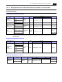
14.1 Temperature Controller/Servo/Inverter Connection . . . . . . . . . . . . . . . . . . . . . . . . . . . . . . . . 14-1
14.1.1
14.1.2
14.1.3
14.1.4
14.1.5
14.1.6
14.1.7
15.
Serial Connection. . . . . . . . . . . . . . . . . . . . . . . . . . . . . . . . . . . . . . . . . . . . . . . . . . . . . . . . . . . . . . . . . . . .
CB100/CB400/CB500/CB700/CB900 (MODBUS RTU) . . . . . . . . . . . . . . . . . . . . . . . . . . . . . . . . . . . . . .
Communication Setting . . . . . . . . . . . . . . . . . . . . . . . . . . . . . . . . . . . . . . . . . . . . . . . . . . . . . . . . . . . . . . .
Available Memory . . . . . . . . . . . . . . . . . . . . . . . . . . . . . . . . . . . . . . . . . . . . . . . . . . . . . . . . . . . . . . . . . . .
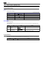
SRV (MODBUS RTU) . . . . . . . . . . . . . . . . . . . . . . . . . . . . . . . . . . . . . . . . . . . . . . . . . . . . . . . . . . . . . . . .
Communication Setting . . . . . . . . . . . . . . . . . . . . . . . . . . . . . . . . . . . . . . . . . . . . . . . . . . . . . . . . . . . . . . .
Available Memory . . . . . . . . . . . . . . . . . . . . . . . . . . . . . . . . . . . . . . . . . . . . . . . . . . . . . . . . . . . . . . . . . . .
SR-Mini (MODBUS RTU). . . . . . . . . . . . . . . . . . . . . . . . . . . . . . . . . . . . . . . . . . . . . . . . . . . . . . . . . . . . . .
Communication Setting . . . . . . . . . . . . . . . . . . . . . . . . . . . . . . . . . . . . . . . . . . . . . . . . . . . . . . . . . . . . . . .
Available Memory . . . . . . . . . . . . . . . . . . . . . . . . . . . . . . . . . . . . . . . . . . . . . . . . . . . . . . . . . . . . . . . . . . .
SR-Mini (Standard Protocol) . . . . . . . . . . . . . . . . . . . . . . . . . . . . . . . . . . . . . . . . . . . . . . . . . . . . . . . . . . .
Communication Setting . . . . . . . . . . . . . . . . . . . . . . . . . . . . . . . . . . . . . . . . . . . . . . . . . . . . . . . . . . . . . . .
Available Memory . . . . . . . . . . . . . . . . . . . . . . . . . . . . . . . . . . . . . . . . . . . . . . . . . . . . . . . . . . . . . . . . . . .
MA900 / MA901 (MODBUS RTU) . . . . . . . . . . . . . . . . . . . . . . . . . . . . . . . . . . . . . . . . . . . . . . . . . . . . . . .
Communication Setting . . . . . . . . . . . . . . . . . . . . . . . . . . . . . . . . . . . . . . . . . . . . . . . . . . . . . . . . . . . . . . .
Available Memory . . . . . . . . . . . . . . . . . . . . . . . . . . . . . . . . . . . . . . . . . . . . . . . . . . . . . . . . . . . . . . . . . . .
SRZ (MODBUS RTU) . . . . . . . . . . . . . . . . . . . . . . . . . . . . . . . . . . . . . . . . . . . . . . . . . . . . . . . . . . . . . . . .
Communication Setting . . . . . . . . . . . . . . . . . . . . . . . . . . . . . . . . . . . . . . . . . . . . . . . . . . . . . . . . . . . . . . .
Available Memory . . . . . . . . . . . . . . . . . . . . . . . . . . . . . . . . . . . . . . . . . . . . . . . . . . . . . . . . . . . . . . . . . . .
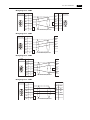
Wiring Diagrams . . . . . . . . . . . . . . . . . . . . . . . . . . . . . . . . . . . . . . . . . . . . . . . . . . . . . . . . . . . . . . . . . . . .
When Connected at COM1 (RS-422 / RS-485): . . . . . . . . . . . . . . . . . . . . . . . . . . . . . . . . . . . . . . . . . . . .
14-1
14-2
14-2
14-2
14-3
14-3
14-3
14-4
14-4
14-4
14-5
14-5
14-5
14-6
14-6
14-6
14-7
14-7
14-7
14-8
14-8
SAIA
15.1 PLC Connection . . . . . . . . . . . . . . . . . . . . . . . . . . . . . . . . . . . . . . . . . . . . . . . . . . . . . . . . . . . 15-1
15.1.1
15.1.2
16.
Serial Connection. . . . . . . . . . . . . . . . . . . . . . . . . . . . . . . . . . . . . . . . . . . . . . . . . . . . . . . . . . . . . . . . . . . .
PCD . . . . . . . . . . . . . . . . . . . . . . . . . . . . . . . . . . . . . . . . . . . . . . . . . . . . . . . . . . . . . . . . . . . . . . . . . . . . . .
Communication Setting . . . . . . . . . . . . . . . . . . . . . . . . . . . . . . . . . . . . . . . . . . . . . . . . . . . . . . . . . . . . . . .
Available Memory . . . . . . . . . . . . . . . . . . . . . . . . . . . . . . . . . . . . . . . . . . . . . . . . . . . . . . . . . . . . . . . . . . .
Wiring Diagrams . . . . . . . . . . . . . . . . . . . . . . . . . . . . . . . . . . . . . . . . . . . . . . . . . . . . . . . . . . . . . . . . . . . .
When Connected at COM1 (RS-422 / RS-485): . . . . . . . . . . . . . . . . . . . . . . . . . . . . . . . . . . . . . . . . . . . .
When Connected at COM2 (RS-232C):. . . . . . . . . . . . . . . . . . . . . . . . . . . . . . . . . . . . . . . . . . . . . . . . . . .
15-1
15-2
15-2
15-2
15-3
15-3
15-3
Siemens
16.1 PLC Connection . . . . . . . . . . . . . . . . . . . . . . . . . . . . . . . . . . . . . . . . . . . . . . . . . . . . . . . . . . . 16-1
16.1.1
16.1.2
16.1.3
17.
Serial Connection. . . . . . . . . . . . . . . . . . . . . . . . . . . . . . . . . . . . . . . . . . . . . . . . . . . . . . . . . . . . . . . . . . . .
S7-200PPI . . . . . . . . . . . . . . . . . . . . . . . . . . . . . . . . . . . . . . . . . . . . . . . . . . . . . . . . . . . . . . . . . . . . . . . . .
Communication Setting . . . . . . . . . . . . . . . . . . . . . . . . . . . . . . . . . . . . . . . . . . . . . . . . . . . . . . . . . . . . . . .
Available Memory . . . . . . . . . . . . . . . . . . . . . . . . . . . . . . . . . . . . . . . . . . . . . . . . . . . . . . . . . . . . . . . . . . .
S7-300/400MPI . . . . . . . . . . . . . . . . . . . . . . . . . . . . . . . . . . . . . . . . . . . . . . . . . . . . . . . . . . . . . . . . . . . . .
Communication Setting . . . . . . . . . . . . . . . . . . . . . . . . . . . . . . . . . . . . . . . . . . . . . . . . . . . . . . . . . . . . . . .
Available Memory . . . . . . . . . . . . . . . . . . . . . . . . . . . . . . . . . . . . . . . . . . . . . . . . . . . . . . . . . . . . . . . . . . .
Wiring Diagrams . . . . . . . . . . . . . . . . . . . . . . . . . . . . . . . . . . . . . . . . . . . . . . . . . . . . . . . . . . . . . . . . . . . .
When Connected at COM1 (RS-422 / RS-485): . . . . . . . . . . . . . . . . . . . . . . . . . . . . . . . . . . . . . . . . . . . .
16-1
16-2
16-2
16-2
16-3
16-3
16-3
16-4
16-4
Yamatake
17.1 Temperature Controller/Servo/Inverter Connection . . . . . . . . . . . . . . . . . . . . . . . . . . . . . . . . 17-1
Serial Connection. . . . . . . . . . . . . . . . . . . . . . . . . . . . . . . . . . . . . . . . . . . . . . . . . . . . . . . . . . . . . . . . . . . . 17-1
17.1.1
17.1.2
17.1.3
17.1.4
18.
SDC35/36 . . . . . . . . . . . . . . . . . . . . . . . . . . . . . . . . . . . . . . . . . . . . . . . . . . . . . . . . . . . . . . . . . . . . . . . . . . 17-2
Communication Setting. . . . . . . . . . . . . . . . . . . . . . . . . . . . . . . . . . . . . . . . . . . . . . . . . . . . . . . . . . . . . . . . 17-2
Available Memory . . . . . . . . . . . . . . . . . . . . . . . . . . . . . . . . . . . . . . . . . . . . . . . . . . . . . . . . . . . . . . . . . . . . 17-2
DMC10 . . . . . . . . . . . . . . . . . . . . . . . . . . . . . . . . . . . . . . . . . . . . . . . . . . . . . . . . . . . . . . . . . . . . . . . . . . . . 17-3
Communication Setting. . . . . . . . . . . . . . . . . . . . . . . . . . . . . . . . . . . . . . . . . . . . . . . . . . . . . . . . . . . . . . . . 17-3
Available Memory . . . . . . . . . . . . . . . . . . . . . . . . . . . . . . . . . . . . . . . . . . . . . . . . . . . . . . . . . . . . . . . . . . . . 17-3
DMC50 (COM) . . . . . . . . . . . . . . . . . . . . . . . . . . . . . . . . . . . . . . . . . . . . . . . . . . . . . . . . . . . . . . . . . . . . . . 17-4
Communication Setting. . . . . . . . . . . . . . . . . . . . . . . . . . . . . . . . . . . . . . . . . . . . . . . . . . . . . . . . . . . . . . . . 17-4
Available Memory . . . . . . . . . . . . . . . . . . . . . . . . . . . . . . . . . . . . . . . . . . . . . . . . . . . . . . . . . . . . . . . . . . . . 17-5
Wiring Diagrams . . . . . . . . . . . . . . . . . . . . . . . . . . . . . . . . . . . . . . . . . . . . . . . . . . . . . . . . . . . . . . . . . . . . . 17-7
When Connected at COM1 (RS-422 / RS-485):. . . . . . . . . . . . . . . . . . . . . . . . . . . . . . . . . . . . . . . . . . . . . 17-7
Yaskawa Electric
18.1 PLC Connection . . . . . . . . . . . . . . . . . . . . . . . . . . . . . . . . . . . . . . . . . . . . . . . . . . . . . . . . . . . 18-1
18.1.1
18.1.2
18.1.3
19.
Serial Connection . . . . . . . . . . . . . . . . . . . . . . . . . . . . . . . . . . . . . . . . . . . . . . . . . . . . . . . . . . . . . . . . . . . . 18-1
Memobus . . . . . . . . . . . . . . . . . . . . . . . . . . . . . . . . . . . . . . . . . . . . . . . . . . . . . . . . . . . . . . . . . . . . . . . . . . 18-2
Communication Setting. . . . . . . . . . . . . . . . . . . . . . . . . . . . . . . . . . . . . . . . . . . . . . . . . . . . . . . . . . . . . . . . 18-2
Available Memory . . . . . . . . . . . . . . . . . . . . . . . . . . . . . . . . . . . . . . . . . . . . . . . . . . . . . . . . . . . . . . . . . . . . 18-2
CP9200SH/MP900 . . . . . . . . . . . . . . . . . . . . . . . . . . . . . . . . . . . . . . . . . . . . . . . . . . . . . . . . . . . . . . . . . . . 18-3
Communication Setting. . . . . . . . . . . . . . . . . . . . . . . . . . . . . . . . . . . . . . . . . . . . . . . . . . . . . . . . . . . . . . . . 18-3
Available Memory . . . . . . . . . . . . . . . . . . . . . . . . . . . . . . . . . . . . . . . . . . . . . . . . . . . . . . . . . . . . . . . . . . . . 18-4
Wiring Diagrams . . . . . . . . . . . . . . . . . . . . . . . . . . . . . . . . . . . . . . . . . . . . . . . . . . . . . . . . . . . . . . . . . . . . . 18-5
When Connected at COM1 (RS-422 / RS-485):. . . . . . . . . . . . . . . . . . . . . . . . . . . . . . . . . . . . . . . . . . . . . 18-5
When Connected at COM2 (RS-232C): . . . . . . . . . . . . . . . . . . . . . . . . . . . . . . . . . . . . . . . . . . . . . . . . . . . 18-7
Yokogawa Electric
19.1 PLC Connection . . . . . . . . . . . . . . . . . . . . . . . . . . . . . . . . . . . . . . . . . . . . . . . . . . . . . . . . . . . 19-1
19.1.1
19.1.2
Serial Connection . . . . . . . . . . . . . . . . . . . . . . . . . . . . . . . . . . . . . . . . . . . . . . . . . . . . . . . . . . . . . . . . . . . . 19-1
FA-M3/FA-M3R. . . . . . . . . . . . . . . . . . . . . . . . . . . . . . . . . . . . . . . . . . . . . . . . . . . . . . . . . . . . . . . . . . . . . . 19-2
Communication Setting. . . . . . . . . . . . . . . . . . . . . . . . . . . . . . . . . . . . . . . . . . . . . . . . . . . . . . . . . . . . . . . . 19-2
Available Memory . . . . . . . . . . . . . . . . . . . . . . . . . . . . . . . . . . . . . . . . . . . . . . . . . . . . . . . . . . . . . . . . . . . . 19-4
PLC_CTL . . . . . . . . . . . . . . . . . . . . . . . . . . . . . . . . . . . . . . . . . . . . . . . . . . . . . . . . . . . . . . . . . . . . . . . . . . 19-5
Wiring Diagrams . . . . . . . . . . . . . . . . . . . . . . . . . . . . . . . . . . . . . . . . . . . . . . . . . . . . . . . . . . . . . . . . . . . . . 19-6
When Connected at COM1 (RS-422 / RS-485):. . . . . . . . . . . . . . . . . . . . . . . . . . . . . . . . . . . . . . . . . . . . . 19-6
When Connected at COM2 (RS-232C): . . . . . . . . . . . . . . . . . . . . . . . . . . . . . . . . . . . . . . . . . . . . . . . . . . . 19-6
19.2 Temperature Controller/Servo/Inverter Connection . . . . . . . . . . . . . . . . . . . . . . . . . . . . . . . . 19-7
19.2.1
19.2.2
19.2.3
20.
Digital Indicating Controller. . . . . . . . . . . . . . . . . . . . . . . . . . . . . . . . . . . . . . . . . . . . . . . . . . . . . . . . . . . . . 19-7
UT350 . . . . . . . . . . . . . . . . . . . . . . . . . . . . . . . . . . . . . . . . . . . . . . . . . . . . . . . . . . . . . . . . . . . . . . . . . . . . . 19-8
Communication Setting. . . . . . . . . . . . . . . . . . . . . . . . . . . . . . . . . . . . . . . . . . . . . . . . . . . . . . . . . . . . . . . . 19-8
Available Memory . . . . . . . . . . . . . . . . . . . . . . . . . . . . . . . . . . . . . . . . . . . . . . . . . . . . . . . . . . . . . . . . . . . . 19-8
UT450 . . . . . . . . . . . . . . . . . . . . . . . . . . . . . . . . . . . . . . . . . . . . . . . . . . . . . . . . . . . . . . . . . . . . . . . . . . . . . 19-8
Wiring Diagrams . . . . . . . . . . . . . . . . . . . . . . . . . . . . . . . . . . . . . . . . . . . . . . . . . . . . . . . . . . . . . . . . . . . . . 19-9
When Connected at COM1 (RS-422 / RS-485):. . . . . . . . . . . . . . . . . . . . . . . . . . . . . . . . . . . . . . . . . . . . . 19-9
MODBUS
20.1 PLC Connection . . . . . . . . . . . . . . . . . . . . . . . . . . . . . . . . . . . . . . . . . . . . . . . . . . . . . . . . . . . 20-1
20.1.1
20.1.2
21.
Serial Connection . . . . . . . . . . . . . . . . . . . . . . . . . . . . . . . . . . . . . . . . . . . . . . . . . . . . . . . . . . . . . . . . . . . . 20-1
MODBUS RTU . . . . . . . . . . . . . . . . . . . . . . . . . . . . . . . . . . . . . . . . . . . . . . . . . . . . . . . . . . . . . . . . . . . . . . 20-2
Communication Setting. . . . . . . . . . . . . . . . . . . . . . . . . . . . . . . . . . . . . . . . . . . . . . . . . . . . . . . . . . . . . . . . 20-2
Available Memory . . . . . . . . . . . . . . . . . . . . . . . . . . . . . . . . . . . . . . . . . . . . . . . . . . . . . . . . . . . . . . . . . . . . 20-3
Wiring Diagrams . . . . . . . . . . . . . . . . . . . . . . . . . . . . . . . . . . . . . . . . . . . . . . . . . . . . . . . . . . . . . . . . . . . . . 20-4
When Connected at COM1 (RS-422 / RS-485):. . . . . . . . . . . . . . . . . . . . . . . . . . . . . . . . . . . . . . . . . . . . . 20-4
When Connected at COM2 (RS-232C): . . . . . . . . . . . . . . . . . . . . . . . . . . . . . . . . . . . . . . . . . . . . . . . . . . . 20-4
Barcode Reader
21.1 Barcode Reader Connection . . . . . . . . . . . . . . . . . . . . . . . . . . . . . . . . . . . . . . . . . . . . . . . . . 21-1
21.1.1
21.1.2
21.1.3
21.1.4
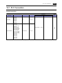
Recommended Models (Operations Verified). . . . . . . . . . . . . . . . . . . . . . . . . . . . . . . . . . . . . . . . . . . . . . . 21-1
Communication Setting. . . . . . . . . . . . . . . . . . . . . . . . . . . . . . . . . . . . . . . . . . . . . . . . . . . . . . . . . . . . . . . . 21-2
I/F Memory . . . . . . . . . . . . . . . . . . . . . . . . . . . . . . . . . . . . . . . . . . . . . . . . . . . . . . . . . . . . . . . . . . . . . . . . . 21-3
Wiring Diagrams . . . . . . . . . . . . . . . . . . . . . . . . . . . . . . . . . . . . . . . . . . . . . . . . . . . . . . . . . . . . . . . . . . . . . 21-4
When Connected at COM2 (RS-232C): . . . . . . . . . . . . . . . . . . . . . . . . . . . . . . . . . . . . . . . . . . . . . . . . . . . 21-4
22.
Slave Communication Function
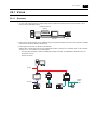
22.1 V-Link . . . . . . . . . . . . . . . . . . . . . . . . . . . . . . . . . . . . . . . . . . . . . . . . . . . . . . . . . . . . . . . . . . . 22-1
22.1.1
22.1.2
22.1.3
22.1.4
22.1.5
Overview . . . . . . . . . . . . . . . . . . . . . . . . . . . . . . . . . . . . . . . . . . . . . . . . . . . . . . . . . . . . . . . . . . . . . . . . . . 22-1
Communication Setting . . . . . . . . . . . . . . . . . . . . . . . . . . . . . . . . . . . . . . . . . . . . . . . . . . . . . . . . . . . . . . . 22-2
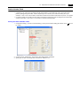
Editor . . . . . . . . . . . . . . . . . . . . . . . . . . . . . . . . . . . . . . . . . . . . . . . . . . . . . . . . . . . . . . . . . . . . . . . . . . . . . 22-2
MONITOUCH. . . . . . . . . . . . . . . . . . . . . . . . . . . . . . . . . . . . . . . . . . . . . . . . . . . . . . . . . . . . . . . . . . . . . . . 22-3
Connection. . . . . . . . . . . . . . . . . . . . . . . . . . . . . . . . . . . . . . . . . . . . . . . . . . . . . . . . . . . . . . . . . . . . . . . . . 22-4
RS-232C . . . . . . . . . . . . . . . . . . . . . . . . . . . . . . . . . . . . . . . . . . . . . . . . . . . . . . . . . . . . . . . . . . . . . . . . . . 22-4
RS-485. . . . . . . . . . . . . . . . . . . . . . . . . . . . . . . . . . . . . . . . . . . . . . . . . . . . . . . . . . . . . . . . . . . . . . . . . . . . 22-5
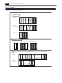
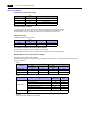
Protocol . . . . . . . . . . . . . . . . . . . . . . . . . . . . . . . . . . . . . . . . . . . . . . . . . . . . . . . . . . . . . . . . . . . . . . . . . . . 22-6
1-byte Character Code List . . . . . . . . . . . . . . . . . . . . . . . . . . . . . . . . . . . . . . . . . . . . . . . . . . . . . . . . . . . 22-10
22.2 Modbus RTU Slave Communication. . . . . . . . . . . . . . . . . . . . . . . . . . . . . . . . . . . . . . . . . . . 22-11
23.
Universal Serial Communication
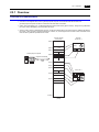
23.1 Overview. . . . . . . . . . . . . . . . . . . . . . . . . . . . . . . . . . . . . . . . . . . . . . . . . . . . . . . . . . . . . . . . . 23-1
Overview of Communication . . . . . . . . . . . . . . . . . . . . . . . . . . . . . . . . . . . . . . . . . . . . . . . . . . . . . . . . . . . 23-1
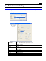
Differences between Connecting to General-purpose Computer and Connecting to PLC . . . . . . . . . . . . 23-2
System Configuration. . . . . . . . . . . . . . . . . . . . . . . . . . . . . . . . . . . . . . . . . . . . . . . . . . . . . . . . . . . . . . . . . 23-2
23.2 Wiring Diagrams . . . . . . . . . . . . . . . . . . . . . . . . . . . . . . . . . . . . . . . . . . . . . . . . . . . . . . . . . . . 23-3
When Connected at COM1 (RS-422 / RS-485): . . . . . . . . . . . . . . . . . . . . . . . . . . . . . . . . . . . . . . . . . . . . 23-3
When Connected at COM2 (RS-232C):. . . . . . . . . . . . . . . . . . . . . . . . . . . . . . . . . . . . . . . . . . . . . . . . . . . 23-4
23.3 Device Connection Setting . . . . . . . . . . . . . . . . . . . . . . . . . . . . . . . . . . . . . . . . . . . . . . . . . . . 23-5
PLC1 . . . . . . . . . . . . . . . . . . . . . . . . . . . . . . . . . . . . . . . . . . . . . . . . . . . . . . . . . . . . . . . . . . . . . . . . . . . . . 23-5
Read/Write Area . . . . . . . . . . . . . . . . . . . . . . . . . . . . . . . . . . . . . . . . . . . . . . . . . . . . . . . . . . . . . . . . . . . . 23-8
23.4 Standard Type Protocol . . . . . . . . . . . . . . . . . . . . . . . . . . . . . . . . . . . . . . . . . . . . . . . . . . . . 23-10
23.4.1
23.4.2
23.4.3
23.4.4
Standard Type Protocol . . . . . . . . . . . . . . . . . . . . . . . . . . . . . . . . . . . . . . . . . . . . . . . . . . . . . . . . . . . . . .
Connection (1 : 1), Transmission Mode (with Sum Check) . . . . . . . . . . . . . . . . . . . . . . . . . . . . . . . . . . .
Connection (1 : 1), Transmission Mode (with Sum Check and CR/LF) . . . . . . . . . . . . . . . . . . . . . . . . . .
Connection (1 : n), Transmission Mode (with Sum Check) . . . . . . . . . . . . . . . . . . . . . . . . . . . . . . . . . . .
Connection (1 : n), Transmission Mode (with Sum Check and CR/LF) . . . . . . . . . . . . . . . . . . . . . . . . . .
Protocol Contents . . . . . . . . . . . . . . . . . . . . . . . . . . . . . . . . . . . . . . . . . . . . . . . . . . . . . . . . . . . . . . . . . .
Transmission Control Code . . . . . . . . . . . . . . . . . . . . . . . . . . . . . . . . . . . . . . . . . . . . . . . . . . . . . . . . . . .
Port Number. . . . . . . . . . . . . . . . . . . . . . . . . . . . . . . . . . . . . . . . . . . . . . . . . . . . . . . . . . . . . . . . . . . . . . .
Command . . . . . . . . . . . . . . . . . . . . . . . . . . . . . . . . . . . . . . . . . . . . . . . . . . . . . . . . . . . . . . . . . . . . . . . .
Sum Check Code (SUM) . . . . . . . . . . . . . . . . . . . . . . . . . . . . . . . . . . . . . . . . . . . . . . . . . . . . . . . . . . . . .
Error Codes . . . . . . . . . . . . . . . . . . . . . . . . . . . . . . . . . . . . . . . . . . . . . . . . . . . . . . . . . . . . . . . . . . . . . . .
Response Time and BUSY . . . . . . . . . . . . . . . . . . . . . . . . . . . . . . . . . . . . . . . . . . . . . . . . . . . . . . . . . . .
Command . . . . . . . . . . . . . . . . . . . . . . . . . . . . . . . . . . . . . . . . . . . . . . . . . . . . . . . . . . . . . . . . . . . . . . . .
RC: Read CHR . . . . . . . . . . . . . . . . . . . . . . . . . . . . . . . . . . . . . . . . . . . . . . . . . . . . . . . . . . . . . . . . . . . .
RM: Read Memory. . . . . . . . . . . . . . . . . . . . . . . . . . . . . . . . . . . . . . . . . . . . . . . . . . . . . . . . . . . . . . . . . .
WC: Write CHR . . . . . . . . . . . . . . . . . . . . . . . . . . . . . . . . . . . . . . . . . . . . . . . . . . . . . . . . . . . . . . . . . . . .
WM: Write Memory . . . . . . . . . . . . . . . . . . . . . . . . . . . . . . . . . . . . . . . . . . . . . . . . . . . . . . . . . . . . . . . . .
TR: Retry Command . . . . . . . . . . . . . . . . . . . . . . . . . . . . . . . . . . . . . . . . . . . . . . . . . . . . . . . . . . . . . . . .
WI: Interrupt Setting Command . . . . . . . . . . . . . . . . . . . . . . . . . . . . . . . . . . . . . . . . . . . . . . . . . . . . . . . .
RI: Interrupt Status Read Command . . . . . . . . . . . . . . . . . . . . . . . . . . . . . . . . . . . . . . . . . . . . . . . . . . . .
Interrupt (ENQ) . . . . . . . . . . . . . . . . . . . . . . . . . . . . . . . . . . . . . . . . . . . . . . . . . . . . . . . . . . . . . . . . . . . .
1-byte Character Code List . . . . . . . . . . . . . . . . . . . . . . . . . . . . . . . . . . . . . . . . . . . . . . . . . . . . . . . . . . .
23-10
23-11
23-12
23-13
23-14
23-15
23-15
23-15
23-15
23-16
23-16
23-17
23-18
23-18
23-19
23-20
23-21
23-22
23-23
23-24
23-25
23-27
23.5 Memory Map. . . . . . . . . . . . . . . . . . . . . . . . . . . . . . . . . . . . . . . . . . . . . . . . . . . . . . . . . . . . . 23-28
Memory . . . . . . . . . . . . . . . . . . . . . . . . . . . . . . . . . . . . . . . . . . . . . . . . . . . . . . . . . . . . . . . . . . . . . . . . . . 23-28
User Memory ($u) . . . . . . . . . . . . . . . . . . . . . . . . . . . . . . . . . . . . . . . . . . . . . . . . . . . . . . . . . . . . . . . . . . 23-28
System Memory ($s) . . . . . . . . . . . . . . . . . . . . . . . . . . . . . . . . . . . . . . . . . . . . . . . . . . . . . . . . . . . . . . . . 23-29
Appendix
Appendix 1 Device Memory Map
Device Memory Map Editing. . . . . . . . . . . . . . . . . . . . . . . . . . . . . . . . . . . . . . . . . . . . . . . . . . . . . . . . . .App1-3
Periodical Reading . . . . . . . . . . . . . . . . . . . . . . . . . . . . . . . . . . . . . . . . . . . . . . . . . . . . . . . . . . . . . . . . .App1-7
Synchronized Reading . . . . . . . . . . . . . . . . . . . . . . . . . . . . . . . . . . . . . . . . . . . . . . . . . . . . . . . . . . . . . .App1-8
Periodical Writing . . . . . . . . . . . . . . . . . . . . . . . . . . . . . . . . . . . . . . . . . . . . . . . . . . . . . . . . . . . . . . . . . .App1-9
Synchronized Writing . . . . . . . . . . . . . . . . . . . . . . . . . . . . . . . . . . . . . . . . . . . . . . . . . . . . . . . . . . . . . .App1-10
Control Memory . . . . . . . . . . . . . . . . . . . . . . . . . . . . . . . . . . . . . . . . . . . . . . . . . . . . . . . . . . . . . . . . . .App1-11
Sampling. . . . . . . . . . . . . . . . . . . . . . . . . . . . . . . . . . . . . . . . . . . . . . . . . . . . . . . . . . . . . . . . . . . . . . . .App1-12
TBL_READ / TBL_WRITE . . . . . . . . . . . . . . . . . . . . . . . . . . . . . . . . . . . . . . . . . . . . . . . . . . . . . . . . . .App1-14
Appendix 2 System Memory
Appendix 3 n : 1 Connection
Appendix 3.1
Appendix 3.2
Multi-link2 . . . . . . . . . . . . . . . . . . . . . . . . . . . . . . . . . . . . . . . . . . . . . . . . . . . . . . . . . . . . . . . . . . . . . . . . .App3-1
System Configuration and Wiring Diagram. . . . . . . . . . . . . . . . . . . . . . . . . . . . . . . . . . . . . . . . . . . . . . .App3-2
Terminating Resistance Setting . . . . . . . . . . . . . . . . . . . . . . . . . . . . . . . . . . . . . . . . . . . . . . . . . . . . . . .App3-2
Setting on the Editor . . . . . . . . . . . . . . . . . . . . . . . . . . . . . . . . . . . . . . . . . . . . . . . . . . . . . . . . . . . . . . . .App3-3
Communication Error . . . . . . . . . . . . . . . . . . . . . . . . . . . . . . . . . . . . . . . . . . . . . . . . . . . . . . . . . . . . . . .App3-4
Multi-link . . . . . . . . . . . . . . . . . . . . . . . . . . . . . . . . . . . . . . . . . . . . . . . . . . . . . . . . . . . . . . . . . . . . . . . . . .App3-5
Wiring Diagrams . . . . . . . . . . . . . . . . . . . . . . . . . . . . . . . . . . . . . . . . . . . . . . . . . . . . . . . . . . . . . . . . . . .App3-6
Setting on the Editor . . . . . . . . . . . . . . . . . . . . . . . . . . . . . . . . . . . . . . . . . . . . . . . . . . . . . . . . . . . . . . . .App3-7
Appendix 4 Ladder Transfer Function
Operating Environment. . . . . . . . . . . . . . . . . . . . . . . . . . . . . . . . . . . . . . . . . . . . . . . . . . . . . . . . . . . . . .App4-1
Setting. . . . . . . . . . . . . . . . . . . . . . . . . . . . . . . . . . . . . . . . . . . . . . . . . . . . . . . . . . . . . . . . . . . . . . . . . . .App4-2
Notes . . . . . . . . . . . . . . . . . . . . . . . . . . . . . . . . . . . . . . . . . . . . . . . . . . . . . . . . . . . . . . . . . . . . . . . . . . .App4-5
Connection Compatibility List
1. Overview
1.1
2-way Communication
1.2
Connection Modes
1.3
Physical Port
1.4
Wiring
1.5
Settings for the Connected Device
1.1 2-way Communication
1.1
2-way Communication
1.1.1
Overview
1-1
The S8 series is equipped with two serial ports for RS-232C and RS-422/485 communication. You can connect two different
models of devices and allow the S8 series to communicate with them at the same time. This is called the 2-way
communication.
Physical ports
S8
Logical ports
PLC1 Temperature controller (company A)
PLC2 PLC (company B)
COM1
COM2
Select a target for connection.
No. of
Ports
Physical Ports
COM1 (RS-422/RS-485)
Serial
COM2 (RS-232C)
Applicable Devices
1
PLC/temperature controller/servo/inverter
1
PLC/temperature controller/servo/inverter/barcode reader/V-Link/
slave communication (Modbus RTU)
• Only the logical port PLC1 can be selected for the following devices and functions. Thus, they cannot be connected at
the same time.
- Devices
Universal serial connection, without PLC connection, AB Control Logix, Siemens S7-200 PPI,
Siemens S7-300/400MPI
- Functions
Multi-link2, multi-link, ladder transfer, Micrex SX variable name cooperation function
System Composition
31 units maximum
S8
COM1
RS-422/RS-485
COM2
RS-232C
PLC
1-2
1. Overview
1.2
Connection Modes
1.2.1
PLC Connection
There are four connection modes below to establish serial communication.
1 : 1 Connection
Overview
• One set of the S8 is connected to one PLC (1 : 1 connection).
• You can make settings for 1 : 1 communication in the [Communication Setting] tab window for the logical ports PLC1 and
PLC2. A communication port is selectable from COM1 and COM2.
PLC
S8
COM1
COM2
RS-232C or RS-422 (RS-485) connection
• The S8 (master station) communicates with a PLC under the PLC’s protocol. Therefore, there is no need to prepare a
communication program for the PLC (slave station).
• The S8 reads the PLC memory for screen display. It is also possible to write switch data or numerical data entered
through the keypad directly to the PLC memory.
Read
PLC
S8
COM1
COM2
Write
Connection
For more information on connection, see “1.4 Wiring” on page 1-10, “1.5 Settings for the Connected Device” on page 1-13, or
the chapters on individual manufacturers.
1.2 Connection Modes
1-3
1 : n Connection (Multi-drop)
Overview
• Multi-drop connection connects one S8 unit to multiple PLCs of the same model as 1 : n connection. (Maximum
connectable PLCs: 31)
• You can make settings for 1 : n communication in the [Communication Setting] tab window for the logical ports PLC1 and
PLC2. COM1 is used as a communication port.
S8
Maximum length (S8 to the terminating PLC) = 500 m
RS-422/RS-485 connection
COM1
FA C TO RY
PLC (company A)
FA C TO RY
ACE
FA C TO RY
ACE
PROGRAMMER
1
FA C TO RY
ACE
PROGRAMMER
ACE
PROGRAMMER
2
PROGRAMMER
3
31
• For models that support multi-drop connection, refer to the list provided at the end of this manual or the chapters on
individual manufacturers.
Connection
For more information on connection, see “1.4 Wiring” on page 1-10, “1.5 Settings for the Connected Device” on page 1-13, or
the chapters on individual manufacturers.
For description of connecting the PLCs, refer to the manual for the corresponding PLC model.
1-4
1. Overview
n : 1 Connection (Multi-link2)
Overview
• One PLC is connected to a maximum of four* S8/V8 units. The S8 series cannot be connected with the V7 and V6 series
as multi-link2.
* The terminating resistance of COM1 on S806M10D is always set to ON. If you use S806M10D in multi-link2
connection, S806M10D is available only in the termination of multi-link2 (master and slave). So, a maximum of two
S806M10D units is available.
• Multi-link2 enables you to establish an original network consisting of a master S8 of local port No. 1 and slave S8 units of
local port Nos. 2, 3, and 4. The master S8 communicates with the PLC directly, and the slave S8 units communicate with
the PLC through the master.
Master
Local port 1
Slave
Local port 2
Slave
Local port 3
Slave
Local port 4
COM2 COM1
COM1
COM1
COM1
RS-485 (2-wire system) connection
RS-232C
PLC
• You can make settings for multi-link2 in the [Communication Setting] tab window for the logical port PLC1.
• Multi-link2 enables PLC1 memory data to be shared among the S8 units.
• Communication speed between the master station and the PLC depend on the setting made on the PLC. The maximum
communication speed between S8 units is 115 kbps, which is higher than the one available with multi-link connection
described in “n : 1 Connection (Multi-link)”.
• For PLCs that support multi-link2 connection, refer to the list provided at the end of this manual or the chapters on
individual manufacturers.
The COM2 port (RS-232C) must be used for PLC connection (1:1 connection). The COM1 port (RS-485, 2-wire system)
must be used for connection between S8 units.
Connection
For more information, see “Appendix 3.1 Multi-link2”.
1.2 Connection Modes
1-5
n : 1 Connection (Multi-link)
Overview
• One PLC is connected to a maximum of 31* S8 units. The S8, V8, V7, and V6 series can be used together.
* The terminating resistance of COM1 on S806M10D is always set to ON. So, S806M10D is available only in the
termination of multi-link.
• Connection Example
Port No. 1
Port No. 2
Port No. 3
Port No. 31
COM1
COM1
COM1
COM1
Maximum length (PLC to the terminating MONITOUCH) = 500 m
RS-485 (2-wire system) connection
PLC1
• You can make settings for multi-link in the [Communication Setting] tab window for the logical port PLC1. For the S8,
COM1 is available for a communication port. For the V8, however, a communication port is selectable from CN1, MJ1,
and MJ2. For the V7 or V6, CN1 is only available.
• Only a PLC for the signal level RS422/RS485 and with a port number is available. For PLCs that support multi-link
connection, refer to the list provided at the end of this manual or the chapters on individual manufacturers.
• Wiring type is RS-485 (2-wire system).
Connection
For more information, see “Appendix 3.2 Multi-link”.
1-6
1.2.2
1. Overview
Temperature Controller/Servo/Inverter Connection
Overview
• The S8 series is connected to temperature controllers, servos, or inverters via serial communication.
• You can make settings for temperature controller/servo/inverter communication in the [Communication Setting] tab
window for the logical ports PLC1 - PLC2.
• The S8 series can be connected to multiple temperature controllers, servos, or inverters of the same model as 1 : n
connection with COM1 port (RS-422/485). (Maximum connectable units: 31)
S8
Maximum length (S8 to the terminating device) = 500 m
RS-485 (2-wire system) connection
COM1
Temperature controller
(company A)
1
2
3
31
Connection
For more information on connection, see “1.4 Wiring” on page 1-10, “1.5 Settings for the Connected Device” on page 1-13, or
the chapters on individual manufacturers.
1.2.3
Barcode Reader Connection
Overview
• The S8 series is connected to a barcode reader as 1 : 1 connection (RS-232C).
• You can make settings for barcode reader communication in the [Communication Setting] tab window for the logical ports
PLC2. COM2 is only available for a communication port.
PI !
490258
030244
Code No.
4902580302474
COM2
RS-232C
Connection
For more information on connection, see “21.1 Barcode Reader Connection”.
7
1.2 Connection Modes
1.2.4
1-7
Slave Communication
Connecting via V-Link, or Modbus RTU is applicable to slave communication using the S8.
V-Link
• “V-Link” is the network where the computer reads from and writes to the internal memory of the S8 series, or PLC1
memory using a dedicated protocol.
Dedicated commands
Read
disc
Write
RESET
F7
PC
S8 series
PLC
• You can make settings for V-Link in the [Communication Setting] tab window for the logical ports PLC2. A communication
port is selectable from COM1 and COM2.
• For more information, see “22.1 V-Link”.
Modbus RTU
• The S8 series is connected to a Modbus RTU master via serial connection.
• The Modbus slave communication memory table is prepared for the S8. The master is allowed to gain access to the
memory table and read/write the PLC1 data.
• For more information, refer to the Modbus Slave Communication manual separately provided.
1-8
1. Overview
1.3
Physical Port
1.3.1
COM1
The COM1 port supports communication via RS-422 (4-wire system), and RS-485 (2-wire system).
Pin Arrangement
COM1
D-sub 9-pin, Female
9
5
6
1
No.
RS-422/RS-485
Signal
Contents
1
+RD
Receive data (+)
Receive data (−)
2
−RD
3
−SD
Send data (−)
4
+SD
Send data (+)
5
0V
Signal ground
NC
Not used
+5 V / +3.3 V
Terminating resistance*
6
7
8
9
* +5 V (S808) or +3.3 V (S806) is output from pin No. 9.
It is used as the power supply for the external terminating resistance. It cannot be used as an external power supply.
Recommended Connector for Communication Cable
Recommended Connector
DDK’s 17JE-23090-02(D8C)-CG
D-sub 9-pin, male, inch screw thread, with hood, RoHS compliant
Applicable Devices
Applicable Devices
PLC, temperature controller, inverter, servo, V-Link, slave communication (Modbus RTU)
1.3 Physical Port
1.3.2
COM2
The COM2 port supports communication via RS-232C.
Pin Arrangement
COM2
D-sub 9-pin, Male
6
1
9
5
No.
RS-232C
Signal
Contents
1
NC
Not used
2
RD
Receive data
3
SD
Send data
4
NC
Not used
5
0V
Signal ground
6
NC
Not used
7
RS
RS request to send
8
CS
CS clear to send
9
NC
Not used
Recommended Connector for Communication Cable
Recommended Connector
DDK’s 17JE-13090-02(D8C)-CG
D-sub 9-pin, female, inch screw thread, with hood, RoHS compliant
Applicable Devices
Applicable Devices
PLC, temperature controller, inverter, servo, barcode reader, V-Link, slave communication (Modbus RTU)
1-9
1-10
1. Overview
1.4
Wiring
This section provides notes on configuring cables. For device wiring diagrams, refer to the chapters on individual
manufacturers.
DANGER
1.4.1
Be sure to turn off the power before connecting cables. Otherwise, electrical shock or damage may occur.
COM1 (RS-422/485) Connection
• Prepare a communication cable on your side. Twisted pairs of 0.3 mm sq. or above are recommended.
• Connect twisted pairs between +SD/−SD and +RD/−RD.
• If the PLC has the terminal for signal ground (SG), connect a wire.
• To use a terminal block for connecting to other device, use Hakko Electronics’ “TC-D9” optionally available.
• The DIP switch on the back of the S8 unit excluding S806M10D is used to set the terminating resistance. For more
information on the DIP switch, refer to the separate S8 Series Hardware Specifications manual.
* S806M10D is not equipped with DIP switches. Therefore, the terminating resistance of COM1 is always set to ON.
Note that there are some restrictions on the configuration including S806M10D when multiple units of S8 and V8 are
connected via multi-link, multi-link2, V-Link and Modbus slave.
• Connect a shielded cable to either the S8 series or the connected device. The connection diagram shows the case
where the shielded cable is connected on the S8 series side. Connect the cable to the FG terminal on the backside of
MONITOUCH.
- RS-422 (4-wire system)
COM1
Dsub 9 (Male)
Name
No.
RS-422 port of the
connected device
Shield
FG
6
1
9
5
+RD
1
Send data (+)
-RD
2
Send data (−)
-SD
3
Receive data (−)
+SD
4
Receive data (+)
SG
5
SG
- RS-485 (2-wire system)
COM1
Dsub 9 (Male)
Name
No.
RS-485 port of the
connected device
Shield
FG
6
1
9
5
+RD
1
Send/receive data (+)
-RD
2
Send/receive data (−)
-SD
3
+SD
4
SG
5
SG
1.4 Wiring
• If noise disturbs communications, connect a shielded cable to both the S8 series and the connected device.
- RS-422 (4-wire system)
COM1
Dsub 9 (Male)
Name
No.
RS-422 port of the
connected device
Shield
FG
6
1
9
5
FG
+RD
1
Send data (+)
-RD
2
Send data (−)
-SD
3
Receive data (−)
+SD
4
Receive data (+)
SG
5
SG
- RS-485 (2-wire system)
COM1
Dsub 9 (Male)
RS-485 port of the
connected device
No.
Name
Shield
FG
6
1
9
5
FG
+RD
1
Send/receive data (+)
-RD
2
Send/receive data (−)
-SD
3
+SD
4
SG
5
SG
Multi-drop connection (1 : n)
In the case of multi-drop connection, wiring between a S8 and a connected device is the same as that for 1 : 1
communication. Meanwhile, for description of wiring between connected devices, refer to the manual issued by the
manufacturer.
• Connection example
COM1
Dsub 9 (Male)
Name
No.
FG
6
1
9
5
RS-422 port of the
connected device
RS-422 port of the
connected device
FG
FG
Send data (+)
+RD
1
Send data (+)
-RD
2
Send data (−)
Send data (−)
-SD
3
Receive data (−)
Receive data (−)
+SD
4
Receive data (+)
Receive data (+)
SG
5
SG
SG
RD terminating resistance: ON
For wiring between connected devices, refer to the
manual issued by the manufacturer.
1-11
1-12
1.4.2
1. Overview
COM2 (RS-232C) Connection
• Prepare a communication cable on your side. Twisted pairs of 0.3 mm sq. or above are recommended.
• Connect a shielded cable to either the S8 series or the connected device. The connection diagram shows the case
where the shielded cable is connected on the S8 series side. Connect the cable to the FG terminal on the backside of
MONITOUCH.
COM2
Dsub 9 (Female)
Name
No.
RS-232C port of the
connected device
Shield
FG
RD
2
Send data
9
5
SD
3
Receive data
6
1
SG
5
SG
RS
7
CS
8
• If noise disturbs communications, establish connections between SD and SG and between RD and SG as pairs
respectively, and connect a shielded cable to both the S8 series and the connected device.
COM2
Dsub 9 (Female)
Name
Shield
FG
FG
9
6
5
1
RS-232C port of the
connected device
No.
Receive data
RD
2
SD
3
SG
5
RS
7
CS
8
SG
SG
Send data
1.5 Settings for the Connected Device
1.5
Settings for the Connected Device
1.5.1
PLC1 to PLC2
1-13
To enable communication with a PLC, a temperature controller, an inverter, etc., the following settings are required to be set
on the editor. You can see the contents of these settings on the S8 Main Menu screen.
For the Main Menu screen, refer to the separate S8 Series Hardware Specifications manual.
Selecting a Device to be Connected
Note on Settings for the Connected Device
Only the logical port PLC1 can be selected for the following devices and functions. Thus, they cannot be connected at the
same time.
- Devices
Universal serial connection, without PLC connection, AB Control Logix, Siemens S7-200PPI,
Siemens S7-300/400MPI
- Functions
Multi-link2, multi-link, ladder transfer, Micrex SX variable name cooperation function
Communication Setting
Connection Mode
Select a connection mode.
1 : 1 / 1 : n / Multi-link / Multi-link2
Available options vary, depending on which device is connected. See the list at the end of this manual.
Signal Level*1
Select a signal level.
RS-232C / RS-422/485
1-14
1. Overview
Baud Rate*1
Select a baud rate.
4800 / 9600 / 19200 / 38400 / 57600 / 76800 / 115K BPS
Data Length*1
Select a data length.
7-Bit / 8-Bit
Stop Bit*1
Select a stop bit.
1-Bit / 2-Bit
Parity*1
Select an option for parity bit.
None / Odd / Even
Target Port No. *1
Specify a port number of the connected device.
0 to 31 (Modbus RTU: 1 to 255)
Transmission Mode*1
Select a transmission mode for the connected device.
This setting is required if a device of Mitsubishi, Omron, Yokogawa, or Yaskawa is in use.
Time-out Time
Specify a period of time allowed for S8 to monitor a response from its connected device. If S8 receives no
response within the specified time, it retries to communicate with it.
0 to 999 (× 10 msec)
Retrials
Specify the number of retrials to be allowed in the event of a timeout during communication. If a timeout
persists even after as many retrials as specified, an error handing routine will take place.
1 to 255
Specify a delay time that elapses before S8 sends the next command after receiving a response from its
connected device. Normally use the default setting.
0 to 255 (× 1 msec)
PLC
Send Delay Time
MONITOUCH
Send delay time “t”
Start Time
Specify a delay time that elapses before S8 starts to send commands upon power-up. If S8 and its
connected device are turned on at the same time and the device is slower to start up, set [Start Time].
0 to 255 (× 1 sec)
Comm. Error Handling
Select an action to be taken in the event of a communication error.
• [Stop]
Communication will be stopped entirely and the communication error screen will be displayed. The
[RETRY] switch is available to retry the reestablishment of communication.
• [Continue]
The communication error message will be displayed in the top-left of the screen. The same
communication will continue until restoration, and screen operation is not allowed then. When
communication has been returned to a normal state, the message disappears and screen operation is
allowed.
• [Disconnect]
No error message will appear and communication will proceed to the next.
However, communication with the device, in which a timeout was detected, will be disconnected.
This setting is valid when [Disconnect] is selected for [Comm. Error Handling].
Reset Condition
• [
Return Time] 1 to 255 sec (× 10 sec)
When the specified time has elapsed, S8 checks the restoration of the device which discontinued
communicating.
• [
Auto-restoration upon screen switch-over]
When the screen is switched, S8 checks the restoration of the device which discontinued
communicating.
Select a code for the connected device. The selected option is reflected through the data displayed on
graphs or trending sampling parts.
DEC/BCD
Code
Specify a byte order in text data. This setting is valid for macro commands that handle text.
LSB → MSB / MSB → LSB
15
[LSB → MSB]
Text Process
0
MSB
2nd byte
LSB
1st byte
MSB
1st byte
LSB
2nd byte
15
[MSB → LSB]
*1
Be sure to match the settings to those made on the connected device.
0
1.5 Settings for the Connected Device
1-15
Detail
Priority
[1] (higher priority) - [2] (lower priority)
Specify a priority taken during 2-way communication. If interrupts from two devices occur at the same time,
communication with these devices will take place in order of priority.
System memory ($s) V7
Compatible (PLC1)
This box is checked if the V7-series screen data has been converted to the data for the S8 series. The
system information relevant to 2-way communication will be stored in memory $P1 and $s. For more
information, see “System Memory” (page App2-1).
System memory ($s) V7
Compatible (PLC2)
This box is checked if the V7-series screen data (including temperature control network/PLC2Way settings)
has been converted to the data for the S8 series.
• Unchecked
$P2:493/494/495 is used as the transfer table control memory.
• Checked
$s762/763/764 is used as the transfer table control memory.
For more information, see “System Memory” (page App2-1).
Transfer Table Control
Memory
Specify the transfer table control memory for PLC1 - PLC2.
The memory specified here is the same as [Control Memory] in the [Device Memory Map Setting] dialog
([System Setting] → [Device Memory Map] → [Device Memory Map Edit] window → [Device Memory Map
Setting] dialog).
For more information, see “Control Memory” (page App1-11).
Target Settings
Connection Check
Memory
Specify a desired memory address used for connection confirmation when communication starts.
This memory address will be used mainly during Modbus communication.
1-16
1.5.2
1. Overview
Read/Write Area
Read/Write Area
Read Area
Specify a memory address used to give commands for display or operation from the PLC to MONITOUCH.
Three words (at the minimum)*1 of consecutive memory addresses are secured.
For more information, see “Read area” (page 1-16).
Write area
This is the area, to which the screen numbers or overlaps displayed on MONITOUCH or a buzzer state will
be written. Three words of consecutive memory addresses are secured.
For more information, see “Write area” (page 1-20).
Calendar
This setting is valid when the S8’s internal clock*2 is not used.
The setting allows the calendar data to be read from the device via the selected port at PLC1 - PLC2.
The calendar data will be updated when:
• The power is turned on.
• STOP → RUN
• The date changes.
• Bit 11 in the read area “n” is set (ON) (0 → 1 leading edge)
*1
*2
More words are required if the sampling function is used:
sampling control memory (three words maximum), sampling data memory (variable depending on the setting)
For more information on the internal clock, refer to the S8 Series Reference Manual.
Read area
The read area is the area where the PLC gives commands for display or operation to MONITOUCH.
Three words (at the minimum) of consecutive memory addresses are secured.
MONITOUCH always reads data from these three words to display and operate according to the commands.
“Display the ERROR screen.”
(a command is given.)
ERROR screen is displayed.
MONITORING
ERROR
Power Supply Error
Turn the unit OFF at
once.
A-1 A-2 A-3 A-4 A-5
B-1 B-2 B-3 B-4 B-5
C-1 C-2 C-3 C-4 C-5
D-1 D-2 D-3 D-4 D-5
Memory addresses are allocated as shown below.
Address
Read area =
n
Contents
Operation
Sub command/data
n+1
Screen status command
n+2
Screen number command
S8 series ← PLC
* Data in these memory addresses is saved at $s460 to 462 of the S8 series internal memory. For more information on the internal memory
($s), refer to the S8 Series Reference Manual.
1.5 Settings for the Connected Device
1-17
Read area “n” (sub command/data)
15
14
13
12
0
0
0
0
11
10
09
08
07
06
05
04
03
02
01
00
0
0
0
0
0
0
0
0
(1) Free
(2) BZ0 [0 → 1] (leading edge)
(3) BZ1 [0 → 1] (leading edge)
(4) BZ2 [1] (level)
(5) Calendar setting ([0 → 1] (leading edge)
(6) System reserved
(1) Free
When data is saved in this area, the same data is written to [Write Area] “n” after the screen has been
displayed. Utilizing this operation, these bits can be used for watch dog monitoring *1 or display scanning *2.
(2) BZ0
A beep (peep) sounds at the leading edge [0 → 1].
(3) BZ1
An error buzzer (peep-peep) sounds at the leading edge [0 → 1].
(4) BZ2
A buzzer (ffeee) sounds continuously while the bit remains [1].
When setting this bit, check [Use Continuous Buzzer Sound] ([System Setting] → [Unit Setting] → [General
Setting])
This bit is valid when the built-in clock is not used. This bit should be used differently depending on whether
the connecting PLC is equipped with the calendar function.
(5) Calendar setting *3
When MONITOUCH is connected to a PLC with calendar function:
When calendar data in the PLC is updated, it can forcibly be read by setting this bit (at the leading edge of [0
→ 1]).
In addition to calendar data update using this bit, calendar data in the PLC is automatically read and updated
when:
• The power is turned on.
• STOP → RUN
• The date changes (AM 00:00:00).
When MONITOUCH is connected to a PLC without calendar function:
A virtual calendar area can be provided by setting [Calendar memory] in the [GD-80 Compatible] tab window
([Read/Write Area] → [GD-80 Compatible]). Then setting this bit (ON) updates the calendar data.
(6) System reserved
*1
This bit is reserved by the system. This bit must be “0”.
Watchdog
When the PLC is communicating with MONITOUCH, there is no means for the PLC to know whether or not MONITOUCH is doing
operations correctly.
To solve this one-way communication, change data in bits 0 to 7 in [Read Area] “n” and check that the same data is saved in bits 0 to 7 in
[Write Area] “n”. This proves that the S8 series is correctly doing operations through communications with the PLC. This verification is
called “watchdog”.
Change data in [Read Area] “n”. (Bits 0 to 7)
MONITORING
A-1 A-2 A-3 A-4 A-5
B-1 B-2 B-3 B-4 B-5
C-1 C-2 C-3 C-4 C-5
D-1 D-2 D-3 D-4 D-5
Data in [Write Area] “n” is changed. (Bits 0 to 7)
*2
Display scanning
This operation can be utilized for display scanning. Change data in bits 0 to 7 in [Read Area] “n” when giving a graphic change command
and check that the same data is saved in bits 0 to 7 in [Write Area] “n”. This can prove that the graphic change command is received and
executed correctly.
[A-1] to [A-5]
ON-display commands
+
Change data in [Read Area] “n”.
(Bits 0 to 7)
MONITORING
A-1 A-2 A-3 A-4 A-5
Data in [Read Area] “n”
(Bits 0 to 7)
=
Data in [Write Area] “n”
(Bits 0 to 7)
B-1 B-2 B-3 B-4 B-5
C-1 C-2 C-3 C-4 C-5
D-1 D-2 D-3 D-4 D-5
[A-1] to [A-5] ON-display: Normal termination
*3
If this bit is used during constant sampling, data sampling timing may be shifted. If this bit is set during constant sampling, we
recommend you to reset the sampling as well.
1-18
1. Overview
Read area “n + 1” (screen status command)
15
14
13
12
11
0
10
09
08
07
06
05
04
03
0
0
0
0
0
02
01
00
(1) Overlap 0
(2) Overlap 1
(3) Overlap 2
(4) System reserved
(5) Global macro execution [0 → 1] (leading edge)
(6) Data sheet output [0 → 1] (leading edge)
(7) Screen hard copy [0 → 1] (leading edge)
(8) Backlight (level)
(9) Screen internal switching (level)
(10) Screen forced switching [0 → 1] (leading edge)
(11) Data read refresh [0 →] (leading edge)
(1) Overlap 0
(2) Overlap 1
(3) Overlap 2
These bits are used for controlling show/hide operations of overlaps.
• Normal overlap or call-overlap
[0 → 1] (leading edge *1): Show
[1 → 0] (falling edge *1): Hide
• Multi-overlap
[0] (level *2): Hide
[1] (level *2): Show
It is necessary to specify library No. 0 to 1023 for [Overlap Library Number] for multi-overlap.
(4) System reserved
This bit is reserved by the system. This bit must be “0”.
(5) Global macro execution
The macro set for [Macro Block] is executed once at [0 → 1] (leading edge).
The macro block number should be specified for [Global Macro Memory] in the dialog that is displayed by
selecting [System Setting] → [Macro Setting].
For more information, refer to the Macro Reference manual provided separately.
(6) Data sheet output
The data sheet is printed out at [0 → 1] (leading edge).
This bit becomes valid when the data sheet function is set.
(7) Screen hard copy
The S8 series screen image is printed out at [0 → 1] (leading edge). This bit becomes valid when a printer
is connected.
It is also possible to make a screen hard copy using an internal switch [Function: Hard Copy].
(8) Backlight
This bit becomes valid when an option other than [Always ON] is selected in the [Backlight] tab window that
is displayed by selecting [System Setting] → [Unit Setting].
[0] (level): OFF when the conditions are satisfied
[1] (level): ON
(9) Screen internal switching
This bit controls screen switching by internal switches.
[0]: Screen switching by internal switches is enabled.
[1]: Screen switching by internal switches is disabled.
* An “internal switch” means a switch you can create for internal processing within MONITOUCH by
selecting [Screen] or [Return] for [Function:] of the switch.
(10) Screen forced switching
This bit is used for switching the screen using the read area “n + 2” when the required screen number has
already been specified in “n + 2”. *3
(11) Data read refresh
All the data display items on the screen are refreshed at [0 → 1] (leading edge). This is applied to every
data display item regardless of the setting for [Process Cycle].
*1
*2
It is possible to make this function work with the bit in the level. For more information, refer to the S8 Series Reference Manual provided
separately.
As an exception, a multi-overlap may appear/disappear at the edge. For more information, refer to the S8 Series Reference Manual
provided separately.
1.5 Settings for the Connected Device
*3
1-19
Usage Example
Step a: Screen change according to read area “n + 2”
Step b: Screen change with an internal switch
Step c: Screen change to the same screen number as step 1 according to read area “n + 2”
In this case, however, the same value is stored in read area “n + 2” so the command is not valid. In such a case, it is possible to forcibly
switch the screen to the screen number contained in read area “n + 2” at the leading edge [0 → 1] of bit 14.
a
D000
D001
D002
Screen No. 5
5
No. 2
Read area “n + 2”
= external screen command
Data in the read area “n + 2” remains “5”
even if the actual screen has been
switched by an internal command.
To show screen No. 5 again using an
external screen command, set [0 → 1]
to bit 14 of read area “n + 1”.
b
No. 2
Screen No. 2
c
Screen forced switching (bit 14)
15
14 13
12 11
10
D000
D001 0
D002
09 08 07
1 0
0 0
0 0
0 0
5
06
05 04
0 0
03 02 01 00
0 0
0 0
Screen No. 5
0
No. 2
Read area “n + 2” (screen number command)
15 14 13 12 11 10 09 08 07 06 05 04 03 02 01 00
(1) Screen number
(1) Screen number command
*1
*1
0 to 9999
These bits are used for switching the screen by an external command.
When a screen number is specified in these bits, the screen is displayed.
Even if the screen has been switched using an internal switch, it is possible to switch the screen using
an external command from the PLC. External commands have priority over internal switches.
Screen No. Error
When MONITOUCH has started communications with the PLC, the screen of the screen number specified in read area “n + 2” is
displayed. If the screen number specified in read area “n + 2” does not exist in the screen data, “Screen No. Error” is displayed on
MONITOUCH.
Data Loading...
Screen No. Error
Before starting communications with the PLC, check the data in [Read Area] “n + 2” and confirm that the screen number to be displayed
at first is specified.
1-20
1. Overview
Write area
This is the area where data is written from [Read Area], such as the displayed screen number, overlap display status, buzzer
sounding status, etc. Three words of consecutive memory addresses are secured.
MONITOUCH writes information to these three words during communications with the PLC.
When the S8 series has completed a display operation, sub command/data in [Read Area] “n” is written.
Backlight OFF!
(The unit status is set to the write area.)
MONITORING
A-1 A-2 A-3 A-4 A-5
B-1 B-2 B-3 B-4 B-5
C-1 C-2 C-3 C-4 C-5
D-1 D-2 D-3 D-4 D-5
The backlight goes OFF when the
screen is not touched for a certain time.
Memory addresses are allocated as shown below.
Address
n
Write area =
Contents
Operation
Same as data in read area “n”
S8 series → PLC
n+1
Screen status
n+2
Displayed screen number
* Data in these memory addresses is saved at $s464 to 466 of the S8 series internal memory. For more information on the
internal memory ($s), refer to the S8 Series Reference Manual.
Write Area “n” (output of read area “n”)
15 14 13 12 11 10 09 08 07 06 05 04 03 02 01 00
0
0
0
0
0
0
0
0
0
0
0
0
(1) Free
(2) BZ0
(3) BZ1
(4) BZ2
(5) Calendar setting
(6) System reserved
(1) Free
(2) BZ0
(3) BZ1
These bits reflect the data in read area “n” at the time MONITOUCH has been finished with processing.
(4) BZ2
(5) Calendar setting
(6) System reserved
Always “0”
1.5 Settings for the Connected Device
1-21
Write area “n + 1” (screen status)
15 14 13 12 11 10 09 08 07 06 05 04 03 02 01 00
0
0
0
0
0
0
(1) Overlap 0
(2) Overlap 1
(3) Overlap 2
(4) System reserved
(5) Global macro execution
(6) Printer busy
(7) Print data transferring
(8) Backlight
(9) Screen internal switching
(10) Screen forced switching
(11) Data read refresh
(1) Overlap 0
(2) Overlap 1
(3) Overlap 2
Overlap status *1
[0]: Hide
[1]: Show
(4) System reserved
Always “0”
(5) Global macro execution
This bit reflects the data in bit 8 of read area “n + 1”.
(6) Printer busy
Printer status *2
[0]: Not busy
[1]: Busy
(7) Print data transferring
Print data transferring status when a print command (hard copy, sample print or data sheet) is executed *2
[0 → 1]: Print data transferring start
[1 → 0]: Print data transferring end
(8) Backlight
Backlight ON/OFF status *3
[0]: OFF
[1]: ON
* Even if bit 11 (backlight) in read area “n + 1” is reset (0: OFF), this bit shows “1” if the backlight is on.
(9) Screen internal switching
This bit reflects the data in bit 13 of read area “n + 1”.
(10)Screen forced switching
This bit reflects the data in bit 14 of read area “n + 1”.
(11) Data read refresh
This bit reflects the data in bit 15 of read area “n + 1”.
1-22
1. Overview
*1 Example:
a. Display overlap No. 0 from read area (n + 1) using an external command.
b. Display overlap No. 0 internally using the [Function: Overlap = ON] switch.
In either case (a or b), bit 0 of write area “n + 1” is set (ON).
In the case of b, the bit in read area “n + 1” remains “0”.
External command for screen display from read area “n + 1”
Line A Paint Process
D001
Screen Change
Line A
Line B
Line C
Line D
Numerical
data
display
Monitor
Error
Alarm
a
When an overlap is displayed on the screen, bit 0
in write area “n + 1” is set to “1”.
Error
15 14
Line A Paint Process
0
0
13
12
0 0
11 10 09
0 0
08
07 06
05 04
03 02
0 0
0 0
0 0
0 0
01
00
0 1
(Write area “n + 1”)
Screen Change
Line A
Line B
Line C
Line D
Numerical
data
display
Monitor
Error
Alarm
b
Error
Internal command for screen display using a switch on the screen
*2
*3
Data of bits 9 and 10 is output to internal memory address $s16. For more information on the internal memory ($s), refer to the S8 Series
Reference Manual.
Data of bit 11 is output to internal memory address $s17. For more information on the internal memory ($s), refer to the S8 Series
Reference Manual.
Write area “n + 2” (displayed screen number)
15 14 13 12 11 10 09 08 07 06 05 04 03 02 01 00
(1) Screen number
(1) Screen number
0 to 9999
Screen number currently displayed
1.5 Settings for the Connected Device
1-23
GD-80 Compatible
GD-80 Compatible
Read/Write Area
Calendar memory
When converting screen data files created on the MONITOUCH GD-80/81S series into those of the S8
series, this option is automatically checked.
• Unchecked:
The memory addresses allocated to the S8 series are applied to the read and write areas. (See page
1-16.)
• Checked:
The memory addresses allocated to the GD-80/81S series are applied to the read and write areas.
For more information on [Read Area] and [Write Area] of the GD-80/81S series, refer to the GD-80
User’s Manual provided separately.
Use this memory area when the connected device is not equipped with the calendar function and the S8
series built-in clock * is not used.
Calendar memory
Follow the steps below to set the calendar memory.
1. Specify the desired memory address for [Calendar memory]. Six words are occupied consecutively.
2. Save calendar data in the calendar memory addresses specified in step 1 in BCD notation.
The allocation of calendar memory is shown below.
Memory
Contents
n
Year (BCD 0 to 99)
n+1
Month (BCD 1 to 12)
n+2
Day (BCD 1 to 31)
n+3
Hour (BCD 0 to 23)
n+4
Minute(s) (BCD 0 to 59)
n+5
Second(s) (BCD 0 to 59)
The day of the week is automatically recognized from the above data. It is not necessary to input any data.
3. Set bit 11 (calendar setting) of read area “n”. At the leading edge of this bit (0 → 1), data in calendar memory is set for
calendar data.
*1 Calendar data is cleared when the power is turned off. When the power is turned on, set calendar data according to the
procedure mentioned above.
*2 When using the calendar memory, automatic reading of calendar data at the time of PLC connection as well as
once-a-day automatic correction is not performed. Consequently, some errors may be introduced. Perform the
procedure described above at regular intervals.
1.5.3
Others
Printer
Select when you connect PictBridge printer to the USB-B port of S8 series.
For more information, refer to the separate S8 Series Reference manual.
1-24
1. Overview
2. ALLEN BRADLEY
2.1
PLC Connection
2.1 PLC Connection
2.1
2-1
PLC Connection
Serial Connection
PLC Selection on
the Editor
Control Logix /
Compact Logix
CPU
1756 Control Logix
Logix 5550
1769 Compact Logix
Channel 0
Channel 0
SLC500
SLC5/03 and later
MicroLogix 1000
MicroLogix
MicroLogix 1100
Signal
Level
Unit/Port
1747-KE DF1
Channel 0
Connection
COM1
COM2
-
Wiring diagram 1 - COM2*1
RS-232C
-
Wiring diagram 2 - COM2
RS-422
Wiring diagram 1 - COM1
-
RS-232C
-
AB’s “1761-CBL-PM02”
RS-232C
RS-232C
*1
Can be connected using the AB’s “1756-CP3” cable.
*2
For the ladder transfer function, see “Appendix 4 Ladder Transfer Function”.
Ladder
Transfer *2
2-2
2.1.1
2. ALLEN BRADLEY
Control Logix / Compact Logix
The logical port PLC1 can only be selected because the tag table is used.
Communication Setting
Editor
Communication setting
(Underlined setting: default)
Item
Connection Mode
Signal Level
Setting
1 : 1 / Multi-link2
Remarks
For multi-link2, be sure to use the same tag
table.
RS-232C / RS-422/485
4800 / 9600 / 19200 / 38400 / 57600 115k bps
Baud Rate
8 bits
Data Length
1 / 2 bits
Stop Bit
None / Odd / Even
Parity
0 to 31
Target Port No.
PLC
Control Logix
Serial port
Item
Setting
MODE
System
Baud Rate
38400
Data Bits
Parity
Stop Bits
Control Line
8
None
1
No Handshake
Remarks
2.1 PLC Connection
System protocol
Item
Protocol
Setting
Remarks
DF1 Point to Point
Station Address
0
NAK Receive Limit
3
ENQ Transmit Limit
3
ACK Timeout
50
Embedded Responses
Error Detection
Autodetect
BCC
Enable Duplicate Detection
Checked
Compact Logix
CH0 - serial port
Item
Setting
MODE
System
Baud Rate
38400
Data Bits
Parity
Stop Bits
Control Line
8
None
1
No Handshake
Remarks
2-3
2-4
2. ALLEN BRADLEY
CH0 - system protocol
Item
Protocol
Setting
Station Address
0
NAK Receive Limit
3
ENQ Transmit Limit
3
ACK Timeout
50
Embedded Responses
Error Detection
Enable Duplicate Detection
Remarks
DF1 Point to Point
Autodetect
BCC
Checked
Available Memory
Create a CSV file by exporting “tag” created by using the ladder tool of the PLC. Then import the CSV file into the editor to
set the PLC memory.
For more information on importing, exporting and creating a tag, refer to “Connection with A•B Control Logix” provided
separately.
2.1 PLC Connection
2.1.2
2-5
SLC500
Communication Setting
Editor
Communication setting
(Underlined setting: default)
Item
Connection Mode
Signal Level
Setting
Remarks
1 : 1 / 1 : n / Multi-link2
RS-232C / RS-422/485
4800 / 9600 / 19200 / 38400 bps
Baud Rate
Data Length
7 / 8 bits
Stop Bit
1 / 2 bits
Parity
None / Even
Target Port No.
0 to 31
PLC
Channel 0
Channel configuration (chan. 0 - system)
Item
Setting
Driver
DF1 Full Duplex
Baud
9600 / 19200 / 38400
Parity
None / Even
Stop Bits
Control Line
Error Detection
Embedded Responses
1/2
No Handshaking
BCC
Auto Detect
Remarks
2-6
2. ALLEN BRADLEY
1747-KE
Jumper JW2
Item
Setting
Remarks
Setting
Remarks
RS-232
RS-422
DF1 port setup menu
Item
Baudrate
19200
Bits Per Character
Parity
8
Even
Stop Bits
1
DF1 full-duplex setup menu
Item
Duplicate Packet Detection
Checksum
Constant Carrier Detect
Message Timeout
Hardware Handshaking
Embedded Response Detect
Setting
Enabled
BCC
Disabled
400
Disabled
Auto Detect
ACK Timeout (× 5 ms)
90
ENQuiry Retries
3
NAK Received Retries
3
Remarks
2.1 PLC Connection
2-7
Available Memory
The available memory setting range varies depending on the PLC model. Be sure to set within the range available for the
PLC. Use [TYPE] when assigning the indirect memory for macro programs.
Memory
TYPE
N
(integer)
00H
B
(bit)
01H
T. ACC
(timer/current value)
02H
T. PRE
(timer/set value)
03H
C. ACC
(counter/current value)
04H
C. PRE
(counter/set value)
05H
I
(input)
06H
O
(output)
07H
S
(status)
08H
T
(timer/control)
09H
C
(counter/control)
0AH
R
(control)
0BH
R. LEN
(control/data length)
0CH
R. POS
(control/data position)
0DH
D
(BCD)
0EH
A
(ASCII)
0FH
F
(FLOAT)
10H
ST
(STRING)
11H
Remarks
Double-word
Make settings for “Data Files” using the ladder tool. Otherwise, “Error Code 10 00” is displayed on MONITOUCH.
For more information, refer to the PLC manual issued by the manufacturer.
2-8
2.1.3
2. ALLEN BRADLEY
Micro Logix
Communication Setting
Editor
Communication setting
(Underlined setting: default)
Item
Connection Mode
Signal Level
Setting
Remarks
1 : 1 / 1 : n / Multi-link2
RS-232C / RS-422/485
4800 / 9600 / 19200 / 38400 bps
Baud Rate
Data Length
7 / 8 bits
Stop Bit
1 / 2 bits
None / Even
Parity
0 to 31
Target Port No.
PLC
Channel Configuration
Channel 0 - system
Item
Setting
Driver
DF1 Full Duplex
Baud
4800 / 9600 / 19200 / 38.4K
Parity
Control Line
None / Even
No Handshaking
Error Detection
CRC / BCC
Embedded Responses
Auto Detect
Remarks
2.1 PLC Connection
2-9
Available Memory
The available memory setting range varies depending on the PLC model. Be sure to set within the range available for the
PLC. Use [TYPE] when assigning the indirect memory for macro programs.
Memory
TYPE
N
(integer)
00H
B
(bit)
01H
T. ACC
(timer/current value)
02H
T. PRE
(timer/set value)
03H
C. ACC
(counter/current value)
04H
C. PRE
(counter/set value)
05H
I
(input)
06H
O
(output)
07H
S
(status)
08H
T
(timer/control)
09H
C
(counter/control)
0AH
R
(control)
0BH
R. LEN
(control/data length)
0CH
R. POS
(control/data position)
0DH
D
(BCD)
0EH
A
(ASCII)
0FH
F
(FLOAT)
10H
ST
(STRING)
11H
L
(LONG)
12H
Remarks
Double-word
Double-word
Make settings for “Data Files” using the ladder tool. Otherwise, “Error Code 10 00” is displayed on MONITOUCH.
For more information, refer to the PLC manual issued by the manufacturer.
2-10
2.1.4
2. ALLEN BRADLEY
Wiring Diagrams
When Connected at COM1 (RS-422 / RS-485):
Wiring diagram 1 - COM1
COM1
Dsub 9 (Male)
Name
No.
FG
1
6
9
5
Name
No.
TXD-
1
+RD
1
RXD-
2
-RD
2
COM
5
-SD
3
RXD+
6
+SD
4
TXD+
9
SG
5
+RS
6
-RS
7
Name
No.
CD
1
PLC
Dsub 9 (Female)
9
5
6
1
* Use shielded twist-pair cables.
When Connected at COM2 (RS-232C):
Wiring diagram 1 - COM2
COM2
Dsub 9 (Female)
Name
No.
FG
RD
2
RXD
2
PLC
Dsub 9 (Female)
9
5
SD
3
TXD
3
9
5
6
1
SG
5
DTR
4
6
1
RS
7
SG
5
CS
8
DSR
6
RTS
7
CTS
8
Name
No.
CD
1
* Use shielded twist-pair cables.
Wiring diagram 2 - COM2
COM2
Dsub 9 (Female)
Name
No.
FG
RD
2
RXD
2
PLC
Dsub 9 (Female)
9
5
SD
3
TXD
3
9
5
6
1
SG
5
DTR
4
6
1
RS
7
SG
5
CS
8
DSR
6
RTS
7
CTS
8
* Use shielded twist-pair cables.
3. Automation Direct
3.1
PLC Connection
3.1 PLC Connection
3.1
3-1
PLC Connection
Serial Connection
PLC Selection on
the Editor
PLC
Port
Port 0
D4-430
D4-440
Direct LOGIC
(K-Sequence)
-
Wiring diagram 4 - COM2
-
Wiring diagram 1 - COM2
RS-422
Wiring diagram 1 - COM1
-
RS-232C
-
Wiring diagram 4 - COM2
RS-232C
-
Wiring diagram 1 - COM2
RS-422
Wiring diagram 1 - COM1
-
Port 2
RS-232C
-
Wiring diagram 3 - COM2
Port 3
RS-422
Wiring diagram 2 - COM1
-
RS-232C
-
Wiring diagram 3 - COM2
RS-232C
-
Wiring diagram 2 - COM2
RS-422
Wiring diagram 3 - COM1
-
RS-232C
-
Wiring diagram 1 - COM2
Port 1
D2-240
DL05
PORT1
D4-450
PORT2
PORT1
PORT2
Port 1
Port 3
D2-250-1
D2-260
*1
Port 1
PORT1
Direct LOGIC
(MODBUS RTU)
COM2
RS-232C
D2-230
D2-250-1
D2-260
DL06
COM1
RS-232C
Port 0
D4-450
Connection
Signal
Level
PORT2
RS-422
Wiring diagram 1 - COM1
-
RS-422
Wiring diagram 2 - COM1
-
RS-232C
-
Wiring diagram 2 - COM2
RS-422
Wiring diagram 3 - COM1
-
For the ladder transfer function, see “Appendix 4 Ladder Transfer Function”.
Ladder
Transfer *1
3-2
3.1.1
3. Automation Direct
Direct LOGIC (K-Sequence)
Communication Setting
Editor
Communication setting
(Underlined setting: default)
Item
Setting
Remarks
1 : 1 / Multi-link2
Connection Mode
Signal Level
RS-232C / RS-422/485
4800 / 9600 / 19200 / 38400 bps
Baud Rate
Data Length
8 bits
Stop Bit
1 / 2 bits
None / Odd / Even
Parity
Target Port No.
0 to 31
D4-450
PORT0
No particular setting is necessary on the PLC. The PLC always performs communication functions using the following
parameters. Set the following parameters on the [Communication Setting] tab window of the editor.
Item
Setting
Baud Rate
Remarks
9600 bps
Parity
Odd
Data Length
8
Stop Bit
1
Data Type
HEX
PORT1
Set parameters into the special register “R772, 773”, then set “AA5A” (HEX) into the setting complete register “R767”. When
the set value at R767 is changed to “AAAA” (HEX), it is regarded as normal; if it is changed to “AAEA” (HEX), it is regarded
as erroneous.
Parameter setting register
Register
Setting
0
R772
0
E
Setting Example
0
Communication protocol
80: K-Sequence
E0: Automatic recognition (Modbus, CCM, K-Sequence)
Communication timeout
0: 800 ms
Response delay time
0: 0 ms
00E0H
K-Sequence
3.1 PLC Connection
Register
Setting
8
7
0
3-3
Setting Example
1
Station number
01 to 1F (HEX)
Baud rate
4: 4800 bps
5: 9600 bps
6: 19200 bps
7: 38400 bps
R773
8701H
Parity stop bit
0: Without parity, stop bit 1
2: Without parity, stop bit 2
8: Odd parity, stop bit 1
A: Odd parity, stop bit 2
C: Even parity, stop bit 1
E: Even parity, stop bit 2
38400 bps
Odd parity
Stop bit 1
Station number 01
PORT2
Set parameters into the special register “R774, 775”, then set “A5AA” (HEX) into the setting complete register “R767”. When
the set value at R767 is changed to “AAAA” (HEX), it is regarded as normal; if it is changed to “AEAA” (HEX), it is regarded
as erroneous.
Parameter setting register
Register
Setting
Setting Example
R774
Same as the setting register R772 for PORT1
00E0H
R775
Same as the setting register R773 for PORT1
8701H
PORT3
Set parameters into the special register “R776, 777”, then set “5AAA” (HEX) into the setting complete register “R767”. When
the set value at R767 is changed to “AAAA” (HEX), it is regarded as normal; if it is changed to “EAAA” (HEX), it is regarded
as erroneous.
Parameter setting register
Register
Setting
Setting Example
R776
Same as the setting register R772 for PORT1
00E0H
R777
Same as the setting register R773 for PORT1
8701H
3-4
3. Automation Direct
D2-240/D2-250-1
PORT1 / PORT2
No particular setting is necessary on the PLC. The PLC performs communication functions using the following parameters.
Set the following parameters on the [Communication Setting] tab window of S8.
Item
Setting
Baud Rate
Remarks
9600 bps
Parity
For PORT2:
19200 bps can be set in the special register.
Odd
Data Length
8
Stop Bit
1
Data Type
HEX
Available Memory
The available memory setting range varies depending on the PLC model. Be sure to set within the range available for the
PLC. Use [TYPE] when assigning the indirect memory for macro programs.
Memory
V
(data register)
TYPE
00H
X
(input)
01H
Y
(output)
02H
C
(internal relay)
03H
S
(stage)
04H
GX
(transmission relay for all stations)
05H
GY
(transmission relay for specified station)
06H
T
(timer/contact)
07H
CT
(counter/contact)
08H
Remarks
3.1 PLC Connection
3.1.2
3-5
Direct LOGIC (MODBUS RTU)
Communication Setting
Editor
Communication setting
(Underlined setting: default)
Item
Setting
Remarks
1 : 1 / 1 : n / Multi-link2
Connection Mode
Signal Level
RS-232C / RS-422/485
4800 / 9600 / 19200 / 38400 bps
Baud Rate
Data Length
8 bits
Stop Bit
1 / 2 bits
Parity
None / Odd / Even
Target Port No.
1
D4-450
PORT1
Set parameters into the special register “R772, 773”, then set “AA5A” (HEX) into the setting complete register “R767”. When
the set value at R767 is changed to “AAAA” (HEX), it is regarded as normal; if it is changed to “AAEA” (HEX), it is regarded
as erroneous.
Parameter setting register
Register
Setting
0
0
E
Setting Example
0
Communication protocol
20: MODBUS RTU
E0: Automatic recognition (Modbus, CCM, K-Sequence)
R772
00E0H
Communication timeout
0: 800 ms
Response delay time
0: 0 ms
8
6
0
1
Station number
01 to 1F (HEX)
R773
Baud rate
4: 4800 bps
5: 9600 bps
6: 19200 bps
7: 38400 bps
Parity stop bit
0: Without parity, stop bit 1
2: Without parity, stop bit 2
8: Odd parity, stop bit 1
A: Odd parity, stop bit 2
C: Even parity, stop bit 1
E: Even parity, stop bit 2
8701H
38400 bps
Odd parity
Stop bit 1
Station number 01
3-6
3. Automation Direct
PORT3
Set parameters into the special register “R776, 777”, then set “5AAA” (HEX) into the setting complete register “R767”. When
the set value at R767 is changed to “AAAA” (HEX), it is regarded as normal; if it is changed to “EAAA” (HEX), it is regarded
as erroneous.
Parameter setting register
Register
Setting
Setting Example
R776
Same as the setting register R772 for PORT1
00E0H
R777
Same as the setting register R773 for PORT1
8701H
D2-250-1
PORT2
Set parameters into the special register “R7655, 7656”, then set “0500” (HEX) into the setting complete register “R7657”.
When the set value at R7657 is changed to “0A00” (HEX), it is regarded as normal; if it is changed to “0E00” (HEX), it is
regarded as erroneous.
Parameter setting register
Register
Setting
0
0
2
Setting Example
0
Communication protocol
20: MODBUS RTU
R7655
0020H
Communication timeout
0: Specified time
Response delay time
0: 0 ms
8
7
0
1
Station number
01 to 7A (HEX)
Baud rate
4: 4800 bps
5: 9600 bps
6: 19200 bps
7: 38400 bps
R7656
8701H
38400 bps
Odd parity
Stop bit 1
Station number 01
Parity stop bit
0: Without parity, stop bit 1
2: Without parity, stop bit 2
8: Odd parity, stop bit 1
A: Odd parity, stop bit 2
C: Even parity, stop bit 1
E: Even parity, stop bit 2
Available Memory
The available memory setting range varies depending on the PLC model. Be sure to set within the range available for the
PLC. Use [TYPE] when assigning the indirect memory for macro programs.
Memory
V
(data register)
TYPE
00H
X
(input)
01H
Y
(output)
02H
C
(internal relay)
03H
S
(stage)
04H
GX
(transmission relay for all stations)
05H
GY
(transmission relay for specified station)
06H
T
(timer/contact)
07H
CT
(counter/contact)
08H
Remarks
3.1 PLC Connection
3.1.3
Wiring Diagrams
When Connected at COM1 (RS-422 / RS-485):
Wiring diagram 1 - COM1
COM1
Dsub 9 (Male)
Name
No.
FG
6
1
9
5
Name
No.
SG
7
+RD
1
+RXD
9
-RD
2
-RXD
10
-SD
3
+CTS
11
+SD
4
+TXD
14
SG
5
-TXD
16
+RS
6
-RTS
18
-RS
7
+RTS
19
-CTS
23
Name
No.
SG
7
* Use shielded twist-pair cables.
PLC
Dsub 25 (Male)
14
1
25
13
Wiring diagram 2 - COM1
COM1
Dsub 9 (Male)
Name
No.
FG
6
1
9
5
+RD
1
+TXD
12
-RD
2
-TXD
13
-SD
3
+RXD
24
+SD
4
-RXD
25
SG
5
Name
No.
RXD-
6
PLC
Dsub 25 (Male)
14
1
25
13
* Use shielded twist-pair cables.
* SU-6M: Terminal block connectable
Wiring diagram 3 - COM1
COM1
Dsub 9 (Male)
Name
No.
FG
+RD
1
SG
7
6
1
-RD
2
TXD+
9
9
5
-SD
3
TXD-
10
+SD
4
RTS+
11
SG
5
RTS-
12
RXD+
13
CTS+
14
CTS-
15
* Use shielded twist-pair cables.
PLC
High density
Dsub 15 (Male)
11
1
15
5
10
3-7
3-8
3. Automation Direct
When Connected at COM2 (RS-232C):
Wiring diagram 1 - COM2
COM2
Dsub 9 (Female)
Name
No.
FG
Name
No.
TXD
2
RD
2
RXD
3
9
5
SD
3
RTS
4
6
1
SG
5
CTS
5
RS
7
SG
7
CS
8
Name
No.
TXD
2
PLC
Dsub 25 (Male)
14
1
25
13
* Use shielded twist-pair cables.
Wiring diagram 2 - COM2
COM2
Dsub 9 (Female)
Name
No.
FG
9
5
6
1
RD
2
RXD
3
SD
3
RTS
4
SG
5
CTS
5
RS
7
SG
7
CS
8
Name
No.
SG
1
PLC
High density
Dsub 15 (Male)
11
1
15
5
10
* Use shielded twist-pair cables.
Wiring diagram 3 - COM2
COM2
Dsub 9 (Female)
Name
No.
FG
RD
2
RXD
3
TXD
4
Name
No.
TXD
2
PLC
RJ12
123456
9
5
SD
3
6
1
SG
5
RS
7
CS
8
* Use shielded twist-pair cables.
Wiring diagram 4 - COM2
COM2
Dsub 9 (Female)
Name
No.
FG
RD
2
RXD
3
SG
13
9
5
SD
3
6
1
SG
5
RS
7
CS
8
* Use shielded twist-pair cables.
PLC
Dsub 15 (Male)
9
1
15
8
4. EATON Cutler-Hammer
4.1
PLC Connection
4.1 PLC Connection
4.1
4-1
PLC Connection
The PLC models shown below can be connected.
Serial Connection
PLC Selection
on the Editor
CPU
ELC-PA10
ELC-PC12
ELC-PH12
ELC-PB14
ELC
*1
Connection
Unit/Port
Signal
Level
COM1
COM2
Programming port on the CPU
unit (COM1)
RS-232C
-
Wiring diagram 1 - COM2
RS-485
Wiring diagram 1 - COM1
-
Communication port on the
CPU unit (COM2)
For the ladder transfer function, see “Appendix 4 Ladder Transfer Function”.
Ladder
Transfer *1
4-2
4.1.1
4. EATON Cutler-Hammer
ELC
Communication Setting
Editor
Communication setting
(Underlined setting: default)
Item
Setting
Signal Level
Baud Rate
Remarks
1 : 1 / 1 : n / Multi-link2
Connection Mode
RS-232C / RS-422/485
4800 / 9600 / 19200 / 38400 / 57600 / 115200 bps
7 / 8 bits
Data Length
Stop Bit
1 / 2 bit
Parity
None / Odd / Even
Target Port No.
1 to 31
PLC
Make the PLC setting using the data register memory “D”. For more information, refer to the PLC manual issued by the
manufacturer.
Available Memory
The available memory setting range varies depending on the PLC model. Be sure to set within the range available for the
PLC. Use [TYPE] when assigning the indirect memory for macro programs.
Memory
TYPE
D
(data register)
X
(input)
01H
Y
(output)
02H
M
(auxiliary relay)
03H
S
(step point)
04H
T
(timer)
05H
Remarks
00H
C
(counter)
06H
32C
(high-speed counter)
07H
Read only
Double-word
4.1 PLC Connection
4.1.2
Wiring Diagrams
When Connected at COM1 (RS-422 / RS-485):
Wiring diagram 1 - COM1
COM1
Dsub 9 (Male)
Name
No.
Name
+
FG
6
1
9
5
+RD
1
-RD
2
-SD
3
+SD
4
SG
5
-
* Use shielded twist-pair cables.
When Connected at COM2 (RS-232C):
Wiring diagram 1 - COM2
COM2
Dsub 9 (Female)
Name
No.
FG
Name
No.
Rx
4
RD
2
Tx
5
9
5
SD
3
GND
8
6
1
SG
5
RS
7
CS
8
* Use shielded twist-pair cables.
PLC
Mini Din (Male)
8
5
6
3
7
2
4
1
4-3
4-4
4. EATON Cutler-Hammer
Please use this page freely.
5.FANUC
5.1
PLC Connection
5.1 PLC Connection
5.1
5-1
PLC Connection
Serial Connection
PLC Selection on
the Editor
CPU
Power Mate
Model H/D
COM1
COM2
RS-422
Wiring diagram 1 COM1
-
JD40
RS-422
Wiring diagram 2 COM1
-
JD42
RS-232C
-
Wiring diagram 1 COM2
16-Model C
JD5B
RS-232C
-
16i-Model A
16i-Model B
18i-Model A
18i-Model B
18-Model C
21i-Model A
21i-Model B
JD36B
30i-Model A
31i-Model A
32i-Model A
*1
Connection
Signal
Level
JD14
Power Mate
i Model H/D
Power Mate
Unit/Port
-
Wiring diagram 2 COM2
RS-232C
JD36A
-
JD54
-
For the ladder transfer function, see “Appendix 5 Ladder Transfer Function”.
Wiring diagram 3 COM2
Ladder
Transfer *1
5-2
5.1.1
5. FANUC
Power Mate
Communication Setting
Editor
Communication setting
(Underlined setting: default)
Item
Setting
Remarks
1:1 / Multi-link2
Connection Mode
Signal Level
RS-232C / RS-422/RS-485
Baud Rate
19200 bps (fixed)
Data Length
8 bits (fixed)
Stop Bit
1 bits (fixed)
Parity
Even (fixed)
Available Memory
The available memory setting range varies depending on the PLC model. Be sure to set within the range available with the
PLC to be used. Use [TYPE] when assigning the indirect memory for macro programs.
Memory
TYPE
Remarks
D
(data table)
00H
X
input relay
01H
Y
output relay
02H
WY as word device
R
internal relay
03H
WR as word device
K
keep relay
04H
WK as word device
T
timer
05H
C
counter
06H
E
extensional relay
07H
WX as word device
WE as word device
5.1 PLC Connection
5.1.2
Wiring Diagrams
When Connected at COM1 (RS-422 / RS-485):
Wiring diagram 1 - COM1
JD14
Half-pitch 20 pin
COM1
Dsub 9 (Male)
Name
No.
FG
6
1
9
5
Name
No.
RDB
1
+RD
1
RDA
2
-RD
2
SDB
3
-SD
3
SDA
4
+SD
4
0V
11
SG
5
+RS
6
-RS
7
JD15
Half-pitch 20 pin
* Use shielded twist-pair cables.
Name
No.
RDB
1
RDA
2
R
R: 120 W 1/2W
Wiring diagram 2 - COM1
JD40
Half-pitch 20 pin
COM1
Dsub 9 (Male)
Name
No.
FG
6
1
9
5
Name
No.
RXD
1
+RD
1
*RXD
2
-RD
2
TXD
3
-SD
3
*TXD
4
+SD
4
RTS
5
SG
5
*RTS
6
+RS
6
CTS
7
-RS
7
*CTS
8
0V
12
* Use shielded twist-pair cables.
5-3
5-4
5. FANUC
When Connected at COM2 (RS-232C):
Wiring diagram 1 - COM2
JD42
Half-pitch 20 pin
COM2
Dsub 9 (Female)
Name
No.
FG
Name
No.
RDB
9
RD
2
SDB
17
0V
18
9
5
SD
3
6
1
SG
5
RS
7
CS
8
* Use shielded twist-pair cables.
Wiring diagram 2 - COM2
JD36A / JD36B / JD5B
Half-pitch 20 pin
COM2
Dsub 9 (Female)
Name
No.
FG
Name
No.
RD
1
RD
2
DR
3
9
5
SD
3
CS
5
6
1
SG
5
CD
7
RS
7
SG
8
CS
8
SD
11
ER
13
RS
15
* Use shielded twist-pair cables.
Wiring diagram 3 - COM2
JD54
Half-pitch 20 pin
COM2
Dsub 9 (Female)
Name
No.
FG
Name
No.
RD
1
RD
2
DR
3
9
5
SD
3
CS
5
6
1
SG
5
CD
7
RS
7
SG
4
CS
8
SD
11
ER
13
RS
15
* Use shielded twist-pair cables.
6. FATEK AUTOMATION
6.1
PLC Connection
6.1 PLC Connection
6.1
6-1
PLC Connection
The PLC models shown below can be connected.
Serial Connection
PLC Selection
on the Editor
CPU
Unit/Port
FBE-20MC
FBE-28MC
FBE-40MC
FB-DTBR
COM2
RS-232C
-
Wiring diagram 1 - COM2
RS-485
Wiring diagram 1 - COM1
-
Port1
(Dsub 15 pin)
RS-232C
-
Wiring diagram 1 - COM2
Port1
(Dsub 9 pin)
RS-232C
-
Wiring diagram 2 - COM2
RS-485
Wiring diagram 2 - COM1
-
Port2
(Terminal block)
*1
Connection
COM1
Programming port on the CPU
unit
FACON FB
series
Signal
Level
For the ladder transfer function, see “Appendix 4 Ladder Transfer Function”.
Ladder
Transfer *1
6-2
6.1.1
6. FATEK AUTOMATION
FACON FB series
Communication Setting
Editor
Communication setting
(Underlined setting: default)
Item
Setting
Remarks
1 : 1 / 1 : n / Multi-link2
Connection Mode
Signal Level
RS-232C / RS-422/485
4800 / 9600 / 19200 / 38400 bps
Baud Rate
7 / 8 bits
Data Length
Stop Bit
1 / 2 bit
Parity
None / Odd / Even
Target Port No.
1 to 31
PLC
Make the PLC setting using the configuration tool “PRO_LADDER”. For more information, refer to the PLC manual issued by
the manufacturer.
Available Memory
The available memory setting range varies depending on the PLC model. Be sure to set within the range available for the
PLC. Use [TYPE] when assigning the indirect memory for macro programs.
Memory
HR
(data register)
TYPE
Remarks
00H
DR
(data register)
01H
X
(input relay)
02H
WX as word device
Y
(output relay)
03H
WY as word device
M
(internal relay)
04H
WM as word device
S
(step relay)
05H
WS as word device
T
(timer/contact)
06H
WT as word device
C
(counter/contact)
07H
WC as word device
RT
(timer/current value)
08H
RC
(counter/current value)
09H
DRC
(32-bit counter/current value)
10H
*1
*1
For items where double-words can be used (Num. Display, Graph, Sampling), data is processed as double-words.
For those where bits or words can be used, data is processed as words consisting of lower 16 bits.
For input:
Upper 16 bits are ignored.
For output: “0” is written for upper 16 bits.
6.1 PLC Connection
6.1.2
Wiring Diagrams
When Connected at COM1 (RS-422 / RS-485):
Wiring diagram 1 - COM1
COM1
Dsub 9 (Male)
Name
No.
FG
6
1
9
5
Name
No.
D+
5
+RD
1
D-
7
-RD
2
FG
10
-SD
3
+SD
4
SG
5
* Use shielded twist-pair cables.
Wiring diagram 2 - COM1
COM1
Dsub 9 (Male)
Name
No.
Name
D+
FG
6
1
9
5
+RD
1
D-
-RD
2
FG
-SD
3
+SD
4
SG
5
* Use shielded twist-pair cables.
PLC
Dsub 15 (Male)
9
1
15
8
6-3
6-4
6. FATEK AUTOMATION
When Connected at COM2 (RS-232C):
Wiring diagram 1 - COM2
COM2
Dsub 9 (Female)
Name
No.
FG
Name
No.
RXD1
1
RD
2
TXD1
2
9
5
SD
3
RTS1
3
6
1
SG
5
CTS1
4
RS
7
GND
6
CS
8
Name
No.
TXD
2
PLC
Dsub 15 (Male)
9
1
15
8
* Use shielded twist-pair cables.
Wiring diagram 2 - COM2
COM2
Dsub 9 (Female)
Name
No.
FG
RD
2
RXD
3
PLC
Dsub 9 (Male)
9
5
SD
3
SG
5
6
1
6
1
SG
5
CTS
7
9
5
RS
7
RTS
8
CS
8
* Use shielded twist-pair cables.
+
7. Fuji Electric
7.1
PLC Connection
7.2
Temperature Controller/Servo/Inverter Connection
7.1 PLC Connection
7.1
7-1
PLC Connection
The PLC models shown below can be connected.
Serial Connection
MICREX-F Series
PLC Selection on
the Editor
MICREX-F series
*1
CPU
Unit/Port
Connection
Signal
Level
COM1
COM2
-
Wiring diagram 1 - COM2
NV1P-x (F55)
NV1L-RS2
RS-232C
NC1P-E (F70) NC1P-S
(F70S)
NC1L-RS2
RS-232C
-
Wiring diagram 1 - COM2
NC1L-RS4
RS-485
Wiring diagram 1 - COM1
-
FFU120B
RS-232C
-
Wiring diagram 1 - COM2
FFK120A
RS-485
Wiring diagram 1 - COM1
-
FPU080H (F80H)
FPU120H (F120H)
FPU120S (F120S)
FPU140S (F140S)
FPU15xS (F15xS)
Ladder
Transfer *1
For the ladder transfer function, see “Appendix 4 Ladder Transfer Function”.
SPB (N Mode), FLEX-PC
PLC Selection on
the Editor
CPU
NS-CPU-xx
NJ-CPU-xx
SPB (N mode) &
FLEX-PC series
NBxx
Unit/Port
NS-RS1
NJ-RS2
NJ-RS4
NB-RS1
NW0LA-RS2
NW0Pxx (SPB)
SPB (N Mode) &
FLEX-PC
CPU
*1
*2
NW0LA-RS4
NS-CPU-xx
NJ-CPU-xx
NBxx
NW0Pxx (SPB)
CPU port
NJ-CPU-B16
RS-232C port
Signal
Level
Connection
COM1
COM2
RS-232C
-
Wiring diagram 1 - COM2
RS-485
Wiring diagram 1 - COM1
-
RS-232C
-
Wiring diagram 1 - COM2
RS-485
Wiring diagram 1 - COM1
-
RS-232C
-
Wiring diagram 1 - COM2
RS-485
Wiring diagram 1 - COM1
-
RS-232C
-
Wiring diagram 3 - COM2
RS-485
(4-wire)
Wiring diagram 1 - COM1
-
RS-485
(2-wire)
Wiring diagram 2 - COM1
-
RS-485
Hakko Electronics’ cable
“D9-FU-SPBCPU” *2
-
RS-232C
-
Wiring diagram 2 - COM2
For the ladder transfer function, see “Appendix 4 Ladder Transfer Function”.
Cable length: XXX-FU-SPBCPU- M ( = 2, 3, 5 m)
Ladder
Transfer *1
7-2
7. Fuji Electric
MICREX-SX, SPB (IEC Mode)
PLC Selection on
the Editor
CPU
COM1
COM2
RS-232C
-
Wiring diagram 4 - COM2
RS-485
Wiring diagram 3 - COM1
-
NP1L-RS2,
NP1L-RS3
RS-232C
-
Wiring diagram 4 - COM2
NP1L-RS4
RS-485
Wiring diagram 3 - COM1
-
NP1L-RS5
RS-485
Wiring diagram 1 - COM1
-
NW0LA-RS2
RS-232C
-
Wiring diagram 3 - COM2
NW0LA-RS4
RS-485
Wiring diagram 3 - COM1
-
NP1L-RS1
NP1Px-xx (SPH)
MICREX-SX
SPH/SPB series
NW0Pxx (SPB)
NP1Px-xx (SPH)
CPU port
RS-485
Hakko Electronics’ cable
“D9-FU-SPHCPU” *2
NW0Pxx (SPB)
CPU port
RS-485
Hakko Electronics’ cable
“D9-FU-SPBCPU” *2
MICREX-SX
SPH/SPB CPU
*1
*2
Connection
Signal
Level
Unit/Port
Ladder
Transfer *1
For the ladder transfer function, see “Appendix 4 Ladder Transfer Function”.
Cable length: XXX-FU-SPHCPU- M, XXX-FU-SPBCPU- M ( = 2, 3, 5 m)
MICREX-SX Model Selection
When the MICREX-SX SPH or SPB series is connected, a mode selection may be required on the S8 editor depending on
the programming tool used on the PLC or the setting on the programming tool.
PLC Programming Tool
PLC
Setting on the S8 Editor
Environment Options for
MICREX-SX
SX-Programmer Expert (D300win)
SPH series
Unchecked *1
SX-Programmer Standard
Checked
*1
PLC Selection
MICREX-SX SPH / SPB series
MICREX-SX SPH / SPB CPU
MICREX-SX T-Link
MICREX-SX OPCN-1
MICREX-SX Ethernet
SX-Programmer Expert (D300win)
SPF Series
SX-Programmer Standard
SX-MODE
N-MODE
FLEX-PC Programmer
*1
*2
Mode
Selection *2
IEC Mode
N Mode
F Mode
IEC Mode
Unchecked *1
MICREX-SX SPH / SPB series
MICREX-SX SPH / SPB CPU
Checked *1
-
Check or uncheck the box for [Express address in MICREX-F
address type] on the [Editor Options] tab window in the
[Environment Options for MICREX-SX] dialog ([Options] →
[MICREX-SX Environment]) on the SX-Programmer Standard
tool.
N Mode
F Mode
SPB (N mode) & FLEX-PC series
SPB (N mode) & FLEX-PC CPU
-
7.1 PLC Connection
7.1.1
MICREX-F Series
Communication Setting
Editor
Communication setting
(Underlined setting: default)
Item
Setting
Remarks
1 : 1 / 1 : n / Multi-link / Multi-link2
Connection Mode
Signal Level
RS-232C / RS-422/485
Baud Rate
4800 / 9600 / 19200 bps
7 / 8 bits
Data Length
Stop Bit
1 / 2 bits
Parity
None / Odd / Even
Target Port No.
0 to 31
PLC
Be sure to match the settings to those made on the [Communication Setting] tab window of the editor.
Mode setting
MODE
Setting
MODE
2
1
0
F
E
3
4 5
1
RS-232C
Command-defined asynchronous
communication (non-procedure)
3
RS-485
Command-defined asynchronous
communication (non-procedure)
6
7
8
9
D C B
Contents
A
* The mode setting switch is common to NV1L-RS2, NC1L-RS2, NC1L-RS4, FFU120B and FFK120A.
Station number setting
ADDRESS
7
Setting
Contents
8
6
9
0
5
4
×10
Station number
1
3
2
7
8
0 to 31
6
9
4
1
5
0
3
×10: the tens place
×1: the ones place
×1
2
* The station number setting switch is common to NC1L-RS4, FFU120B and FFK120A.
It is not provided on NV1L-RS2 nor NC1L-RS2.
7-3
7-4
7. Fuji Electric
Transmission setting
NV1L-RS2, NC1L-RS2, NC1L-RS4, FFU120B
Switch
Contents
OFF
Initial file
Provided
Not provided
Even
Odd
Data bit length
7 bits
8 bits
Stop bit length
1 bit
2 bits
19200
9600
7
Parity
6
Parity bit
5
4
E.g.) Editor Default Setting
ON
7
Initializing method
8
ON
Switch
8
6
5
4
3
Baud rate
1
ON
ON
OFF
OFF
ON
1
2
ON
2
3
FFK120A
• Character switches
Switch
Contents
OFF
Initial file
Provided
Not provided
6
Parity bit
Even
Odd
5
Data bit length
7 bits
8 bits
4
Stop bit length
2 bits
1 bit
-
OFF
-
OFF
-
OFF
ON
5
Parity
6
7
E.g.) Editor Default Setting
7
Initializing method
8
ON
Switch
8
2
Not used
1
1
3
2
4
3
• Baud rate setting switches
Set a switch to the ON position.
Switch
Contents
Example: 19,200 bps
8
Not used
7
19,200 bps
6
9,600 bps
7
5
4,800 bps
6
4
2,400 bps
4
3
1,200 bps
3
2
600 bps
2
1
300 bps
1
ON
8
5
7.1 PLC Connection
7-5
Available Memory
The available memory setting range varies depending on the PLC model. Be sure to set within the range available with the
PLC to be used. Use [TYPE] when assigning the indirect memory for macro programs.
Memory
TYPE
00H
Remarks
M
(auxiliary relay)
WM as word device
K
(keep relay)
01H
WK as word device
B
(input/output relay)
02H
WB as word device
L
(link relay)
09H
WL as word device
F
(special relay)
0AH
WF as word device
TS
(timer/set value)
0BH
*1
TR
(timer/current value)
0CH
*1
W9
(0.1-sec timer/current value)
0DH
*1
CS
(counter/set value)
0EH
*1
CR
(counter/current value)
0FH
*1
BD
(data memory)
10H
*1
WS
(step relay)
11H
*2
Wn
(file memory)
12H
*3, *4
*1
*3
For items where double-words can be used (Num. Display, Graph, Sampling), data is processed as double-words.
For those where bits or words can be used, data is processed as words consisting of lower 16 bits.
For input: Upper 16 bits are ignored.
For output: “0” is written for upper 16 bits.
Byte device such as step relay is processed as described below.
For input: Upper 8 bits are “0”.
For output: Lower 8 bits are written.
To set up the file memory on the editor, enter “file number” + “: (colon)” + “address” in order.
Example: W30 : 00002
*4
Define the file area as “SI”.
*2
Address
Colon
File number
7-6
7.1.2
7. Fuji Electric
SPB (N Mode) & FLEX-PC Series
Communication Setting
Editor
Communication setting
(Underlined setting: default)
Item
Setting
Remarks
1 : 1 / 1 : n / Multi-link2
Connection Mode
Signal Level
RS-232C / RS-422/485
4800 / 9600 / 19200 / 38400 bps
Baud Rate
7 / 8 bits
Data Length
Stop Bit
1 / 2 bits
Parity
None / Odd / Even
Target Port No.
0 to 31
PLC
Be sure to match the settings to those made on the [Communication Setting] tab window of the editor.
NS-RS1, NJ-RS2, NJ-RS4, NB-RS1
Mode setting
MODE
Setting
MODE
2
1
0
F
E
3
4 5
Contents
1
RS-232C
Command-defined asynchronous
communication (non-procedure)
3
RS-485
Command-defined asynchronous
communication (non-procedure)
6
7
8
9
D C B
A
Station number setting
ADDRESS
7
Setting
Contents
8
6
9
0
5
4
×10
Station number
1
3
2
7
8
6
0 to 31
×10: the tens place
×1: the ones place
9
5
0
4
×1
1
3
2
* The station number setting switch is not provided on NJ-RS2.
Transmission setting
ON
OFF
Switch
Initial file
Provided
Not provided
Even
Odd
7
Data bit length
7 bits
8 bits
6
Stop bit length
1 bit
2 bits
5
19200
9600
4
Switch
Contents
Initializing method
7
Parity
6
Parity bit
5
4
E.g.) Editor Default Setting
ON
8
8
3
1
Baud rate
ON
ON
OFF
1
2
ON
2
3
OFF
ON
7.1 PLC Connection
7-7
NW0LA-RS2, NW0LA-RS4 (Parameter Setting)
On the PLC loader, set parameters for general communications.
Be sure to match the settings to those made on the [Communication Setting] tab window of the editor.
Item
Setting
Mode
General (Command asyn)
Station No.
RS-232C: 0, RS-485: 0 to 31
Initialize method
Set parameters
Baud rate
4800 / 9600 / 19200 / 38400
Parity
Odd / Even / None
Data bits
8/7
Stop bits
1/2
Remarks
These settings can also be specified for
the parameter area.
For more information, refer to the
MICREX-SX SPB Series User’s Manual
<Communication Adapter> (FEH405).
Notes on use of 2-wire connection with NW0LA-RS4
The settings show above are not enough to establish a 2-wire connection with NW0LA-RS4.
To establish a connection, select [Initial file transfer] for [Initial Setting Mode] on the PLC loader, and select 2-wire
connection for [485 mode] in the initial setting file.
For more information, refer to the MICREX-SX SPB Series User’s Manual <Communication Adapter> (FEH405).
Available Memory
The available memory setting range varies depending on the PLC model. Be sure to set within the range available with the
PLC to be used. Use [TYPE] when assigning the indirect memory for macro programs.
Standard Memory
D
(data register)
TYPE
Remarks
00H
W
(link register)
01H
M
(internal relay)
02H
WM as word device
L
(latch relay)
03H
WL as word device
X
(input relay)
04H
WX as word device
Y
(output relay)
05H
WY as word device
R
(file register)
06H
TN
(timer/current value)
07H
CN
(counter/current value)
08H
T
(timer/contact)
09H
C
(counter/contact)
0AH
WS
(step relay)
0BH
7-8
7.1.3
7. Fuji Electric
SPB (N Mode) & FLEX-PC CPU
Communication Setting
Editor
Communication setting
(Underlined setting: default)
Item
Setting
Signal Level
Remarks
1 : 1 / Multi-link2
Connection Mode
RS-232C / RS-422/485
Baud Rate
19200 bps
Data Length
8 bits
Stop Bit
1 bit
Parity
Odd
Target Port No.
When connecting MONITOUCH to the RS-232C port on
NJ-CPU-B16, select [RS-232C]. In other cases, select
[RS-485].
0
PLC
SPB, FLEX-PC CPU Port
No particular setting is necessary on the PLC.
Built-in RS-232C Port on NJ-CPU-B16
On the PLC loader, set parameters for the built-in RS-232C port.
Be sure to match the settings to those made on the [Communication Setting] tab window of the editor.
Available Memory
The available memory is the same as the one described in “7.1.2 SPB (N Mode) & FLEX-PC Series”.
7.1 PLC Connection
7.1.4
7-9
MICREX-SX SPH/SPB Series (IEC Mode)
Communication Setting
Editor
Communication setting
(Underlined setting: default)
Item
Setting
Remarks
1 : 1 / Multi-link2
Connection Mode
Signal Level
RS-232C / RS-422/485
4800 / 9600 / 19200 / 38400 bps
Baud Rate
Data Length
8 bits
Stop Bit
For the SPH series:
Do not change the default setting.
1 / 2 bits
Parity
None / Odd / Even
Target Port No.
0 to 31
PLC
NP1L-RS1 , NP1L-RS2 , NP1L-RS3 , NP1L-RS4 , NP1L-RS5
Mode setting
MODE
A
MODE
B C D
Setting
E
9
8
7
F
0
1
6
5
4 3
RS1, 2, 4
RS-232C Port
RS-485 Port
RS3, 5
CH1
CH2
0
General equipment
General equipment
1
Loader
General equipment
2
General equipment
Loader
3
Loader
Loader
4
General equipment
General equipment
5
Not used
6
Modem loader 19200
bps
7
Self-diagnosis mode 1
8
Self-diagnosis mode 2
9
Modem loader 19200
bps
Loader
A
Modem loader
9600 bps
General equipment
B
Modem loader
9600 bps
Loader
C
Modem loader 38400
bps
General equipment
D
Modem loader 38400
bps
Loader
E
Modem loader 76800
bps
General equipment
F
Modem loader 115200
bps
Modem loader 115200
bps
2
Remarks
RS3 and 5 are not used.
General equipment
* Set the port (or CH No.) where the S8 is connected to “loader”.
Communication parameters are fixed to 38400 bps (baud rate), 8 bits (data length), 1 bit (stop bit), and even (parity).
* When the PLC is connected with the S8, the station number setting switch for RS-485 is not used.
7-10
7. Fuji Electric
NW0LA-RS2, NW0LA-RS4 (Parameter Setting)
On the PLC loader, set parameters for general communications.
Be sure to match the settings to those made on the [Communication Setting] tab window of the editor.
Item
Setting
Mode
Loader
Baud rate
4800 / 9600 / 19200 / 38400
Parity
Odd / Even / None
Data bits
8
Stop bits
1/2
Remarks
Available Memory
Variable name cooperation function
The variable name cooperation function can be used only for PLC1. For memory assignment, basically use the
variable name cooperation function. We recommend you to define the area (variable) that is used for
communications with the S8 as “AT”.
The available memory setting range varies depending on the PLC model. Be sure to set within the range available for the
PLC. Use [TYPE] when assigning the indirect memory for macro programs.
Memory
%IX
(input memory) *1
%QX
TYPE
Remarks
-
%IW as word device, %ID as double-word device
(output memory) *1
-
%QW as word device, %QD as double-word device
%MX1.
(standard memory)
02H
%MX3.
(retain memory)
04H
%MW3. as word device, %%MD3. as double-word device
%MX10.
(system memory)
08H
%MW10. as word device, %MD10. as double-word device
*1
%MW1. as word device, %MD1. as double-word device
For the input/output memory, the variable name cooperation function of the PLC1 must be used. Indirect designation is not available with
the input/output memory.
Indirect Memory Designation
Specify the CPU number in the expansion code.
7.1 PLC Connection
7.1.5
7-11
MICREX-SX SPH/SPB Series (N Mode / F Mode)
Communication Setting
The communication setting is the same as the one described in “7.1.4 MICREX-SX SPH/SPB Series (IEC Mode)”.
Available Memory
The available memory setting range varies depending on the PLC model. Be sure to set within the range available with the
PLC to be used. Use [TYPE] when assigning the indirect memory for macro programs.
Memory
X
(input memory) *1
Y
M
TYPE
Remarks
-
X as bit device, WX as word device, DX as double-word device
(output memory) *1
-
Y as bit device, WY as word device, DY as double-word device
(standard memory)
02H
M as bit device, WM as word device, DM as double-word device
L
(retain memory)
04H
L as bit device, WL as word device, DL as double-word device
SM
(system memory)
08H
SM as bit device, WSM as word device, DSM as double-word device
*1
Input/output memory does not operate normally unless you import the “*.ini” file created using [Export Device Information] in the PLC
programming tool. Indirect designation is not available with the input/output memory.
Indirect Memory Designation
Specify the CPU number in the expansion code.
7.1.6
MICREX-SX SPH/SPB CPU (IEC Mode)
Communication Setting
Editor
Communication setting
(Underlined setting: default)
Item
Connection Mode
Signal Level
Baud Rate
Setting
1 : 1 / Multi-link2
RS-422/485
38400 bps
Data Length
8 bits
Stop Bit
1 bit
Parity
Target Port No.
Remarks
Do not change the setting from default.
Even
0 to 31
PLC
No particular setting is necessary on the PLC.
Communication parameters are fixed to 38400 bps (baud rate), RS-422/485 (signal level), 8 bits (data length), 1 bit (stop bit),
and even (parity).
Available Memory
The available memory is the same as the one described in “7.1.4 MICREX-SX SPH/SPB Series (IEC Mode)”.
7-12
7.1.7
7. Fuji Electric
MICREX-SX SPH/SPB CPU (N Mode / F Mode)
Communication Setting
The communication setting is the same as the one described in “7.1.6 MICREX-SX SPH/SPB CPU (IEC Mode)”.
Available Memory
The available memory is the same as the one described in “7.1.5 MICREX-SX SPH/SPB Series (N Mode / F Mode)”.
7.1 PLC Connection
7.1.8
Wiring Diagrams
When Connected at COM1 (RS-422 / RS-485):
Wiring diagram 1 - COM1
COM1
Dsub 9 (Male)
Name
No.
Name
SDA
FG
6
1
9
5
+RD
1
SDB
-RD
2
RDA
-SD
3
RDB
+SD
4
SG
SG
5
* Use shielded twist-pair cables.
Wiring diagram 2 - COM1
COM1
Dsub 9 (Male)
Name
No.
Name
SDA
FG
+RD
1
SDB
6
1
-RD
2
RDA
9
5
-SD
3
RDB
+SD
4
SG
SG
5
* Use shielded twist-pair cables.
Wiring diagram 3 - COM1
COM1
Dsub 9 (Male)
Name
No.
FG
6
1
9
5
Name
No.
SDB
1
+RD
1
SDA
2
-RD
2
SG
5
-SD
3
RDB
8
+SD
4
RDA
9
SG
5
* Use shielded twist-pair cables.
PLC
Dsub 9 (Female)
9
5
6
1
7-13
7-14
7. Fuji Electric
When Connected at COM2 (RS-232C):
Wiring diagram 1 - COM2
COM2
Dsub 9 (Female)
Name
No.
FG
Name
No.
SD
2
RD
2
RD
3
9
5
SD
3
RS
4
6
1
SG
5
CS
5
RS
7
DR
6
CS
8
SG
7
CD
8
Name
No.
RD
2
* Use shielded twist-pair cables.
PLC
Dsub 25 (Male)
14
1
25
13
Wiring diagram 2 - COM2
COM2
Dsub 9 (Female)
Name
No.
FG
RD
2
SD
3
9
5
SD
3
CTS
4
6
1
SG
5
RTS
5
RS
7
SG
7
CS
8
Name
No.
RD
2
PLC
Dsub 15 (Male)
9
1
15
8
* Use shielded twist-pair cables.
Wiring diagram 3 - COM2
COM2
Dsub 9 (Female)
Name
No.
FG
RD
2
SD
3
PLC
Dsub 9 (Female)
9
5
SD
3
SG
5
9
5
6
1
SG
5
RS
7
6
1
RS
7
CS
8
CS
8
Name
No.
RD
2
* Use shielded twist-pair cables.
Wiring diagram 4 - COM2
COM2
Dsub 9 (Female)
Name
No.
FG
RD
2
SD
3
PLC
Dsub 9 (Male)
9
5
SD
3
ER
4
6
1
6
1
SG
5
SG
5
9
5
RS
7
DR
6
CS
8
RS
7
CS
8
* Use shielded twist-pair cables.
7.2 Temperature Controller/Servo/Inverter Connection
7.2
7-15
Temperature Controller/Servo/Inverter Connection
The controllers shown below can be connected.
Temperature Controller
PLC Selection on the
Editor
Model
Connection
Signal
Level
Port
COM1
COM2
Lst File
PYX
(MODBUS RTU)
PYX4xx
PYX5xx
PYX9xx
*1
Terminal block
RS-485
Wiring diagram 1 - COM1
-
PYX.Lst
PXR
(MODBUS RTU)
PXR3xx
PXR4xx
PXR5xx
PXR7xx
PXR9xx
*1
Terminal block
RS-485
Wiring diagram 1 - COM1
-
PXR.Lst
PXG
(MODBUS RTU)
PXG4xx
PXG5xx
PXG9xx
*1
Terminal block
RS-485
Wiring diagram 1 - COM1
-
F_PXG.Lst
PXH
(MODBUS RTU)
PXH9xx
*1
Terminal block
RS-485
Wiring diagram 2 - COM1
-
F_PXH.Lst
PUM
(MODBUS RTU)
PUMxx
Terminal block
(base)
RS-485
Wiring diagram 2 - COM1
-
F_PUMA_B.Lst
F_PUME.Lst
*1
Select a model on which Modbus communication is available.
Power Monitor Unit
PLC Selection
on the Editor
F-MPC04P
(loader)
Series
Name
Model
Port
Connection
Signal
Level
COM1
COM2
F-MPC04P
UM02-AR2
UM02-AR3
UM02-AR4
RS-485
connector
RS-485
Wiring diagram 3 - COM1
-
F-MPC04P.Lst
F-MPC04
UM01-ARxx
Terminal
block
RS-485
Wiring diagram 4 - COM1
-
UM01_ARA4.Lst
F-MPC04P
UM02-AR3
Terminal
block
RS-485
Wiring diagram 4 - COM1
-
UM02-AR2
UM02_AR2.Lst
UM02-AR4
F-MPC04S
*1
*1
F-MPC50
UM50xx
*1
F-MPC55
UM55V
FePSU
*1
UM03-AR3x
UM45xx
F-MPC60B
UM4Bxx
*1
UM42Cxx
*1
UM42Fxx
*1
UM43FDxx
*1
UM43FGxx
*1
UM44Bxx
*1
UM44CDxx
*1
UM44FGxx
*1
EAxx
EGxx
SAXX
SGxx
UM02_AR3.Lst
UM02_AR4.Lst
UM5ACxx
F-MPC30
F-MPC series /
FePSU
Lst File
Terminal
block
RS-485
Wiring diagram 4 - COM1
-
UM03_ARA3G.L
st
Terminal
block
RS-485
Wiring diagram 4 - COM1
-
UM5A.Lst
Terminal
block
RS-485
Wiring diagram 4 - COM1
-
UM50.Lst
Terminal
block
RS-485
Wiring diagram 4 - COM1
-
UM55V.Lst
UM4_UM42_UM
43.Lst
Terminal
block
RS-485
Wiring diagram 4 - COM1
-
UM44.Lst
Terminal
block
RS-485
Wiring diagram 5 - COM1
Select a model on which RS-485 communication is available.
-
FePSU.Lst
7-16
7. Fuji Electric
Inverter
PLC Selection on the
Editor
Model
Port
Signal
Level
Connection
COM1
COM2
Lst File
FVR-E11S
(MODBUS RTU)
FVRxxE11S-x
Touch panel
connector
RS-485
Wiring diagram 6 - COM1
-
FVR-E11S(Mo
dbus).Lst
FVR-C11S
(MODBUS RTU)
FVRxxC11S-x
OPC-C11S-RSx
RS-485
Wiring diagram 7 - COM1
-
FVR-C11S(Mo
dbus).Lst
FRENIC5000G11S /
P11S (MODBUS RTU)
FRNxxG11S-x
FRNxxP11S-x
Terminal block
RS-485
Wiring diagram 8 - COM1
-
FRENIC5000G
11S_P11S(Mod
bus).Lst
Wiring diagram 9 - COM1
-
Wiring diagram 8 - COM1
-
FRENIC5000V
G7S(Modbus).
Lst
Wiring diagram 10 - COM1
-
F-Mini.Lst
Wiring diagram 10 - COM1
-
RS-485
connector
FRENIC5000VG7
(MODBUS RTU)
FRNxxVG7S-x
FRENIC-Mini
(MODBUS RTU)
FRNxxC1S-x
OPC-VG7-RS
(communication
board)
OPC-C1-RS
(communication
board)
RS-485
RS-485
Touch panel
connector
FRENIC-Eco
(MODBUS RTU)
FRNxxF1S-x
OPC-F1-RS
(communication
board)
RS-485
Touch panel
connector
FRENIC-Multi
(MODBUS RTU)
FRNxxE1S-x
FRENIC-MEGA
(MODBUS RTU)
OPC-E1-RS
(communication
board)
FRNxxxG1x-xx
Touch panel
connector
Terminal block on
control circuit
Wiring diagram 8 - COM1
-
Wiring diagram 10 - COM1
-
Wiring diagram 10 - COM1
-
Wiring diagram 10 - COM1
-
Wiring diagram 8 - COM1
-
RS-485
F-Eco(Modbus)
.Lst
F-Multi.Lst
RS-485
FRENIC-MEG
A(Modbus).Lst
IH Inverter
PLC Selection on the
Editor
Model
Port
Signal
Level
Connection
COM1
COM2
Lst File
HFR-C9K
HFR030C9Kxx
HFR050C9Kxx
HFR-OPC01
(communication
board)
RS-485
Wiring diagram 13 - COM1
-
F_HFR.Lst
HFR-C11K
HFR3.0C11Kxx
HFR5.0C11Kxx
HFR7.0C11Kxx
Terminal block
RS-485
Wiring diagram 8 - COM1
-
HFR-C11K.Lst
AC Power Monitor
PLC Selection on the
Editor
PPMC
(MODBUS RTU)
*1
Model
PPMCxx
Port
*1
Terminal block
Signal
Level
RS-232C
RS-485
Connection
COM1
COM2
-
Wiring diagram 1 - COM2
Wiring diagram 1 - COM1
-
Lst File
F-PPMC.Lst
Select a model on which RS-485 or RS-232C communication is available.
Servo Amplifier
PLC Selection on the
Editor
Model
FALDIC-a series
RYSxx
ALPHA5
(MODBUS RTU)
RYTxxxx5VVx
*1
Port
*1
Signal
Level
Connection
COM1
COM2
Lst File
CN3
RS-485
Wiring diagram 12 - COM1
-
F_FAL-A.Lst
CN3A
RS-485
Wiring diagram 14 - COM1
-
ALPHA5.Lst
Select a model on which host interface: universal communication (RS-485) is available.
7.2 Temperature Controller/Servo/Inverter Connection
7-17
Recorder
PLC Selection on the
Editor
PHR (MODBUS RTU)
Model
Port
PHRxx
Terminal block
Signal
Level
RS-485
Connection
COM1
COM2
Wiring diagram 2 - COM1
-
Lst File
F_PHR.Lst
Digital Panel Meter
PLC Selection on the
Editor
WA5000
Model
WA5xx
*1
Port
*1
Modular Jack
Signal
Level
RS-232C
RS-485
Connection
COM1
COM2
-
Wiring diagram 2 - COM2
Wiring diagram 11 - COM1
-
Lst File
WA5000.Lst
Select a model on which RS-485 or RS-232C communication is available.
AC Power Regulator
PLC Selection on the
Editor
APR-N
(MODBUS RTU)
Model
RPNExxxx-xxZAM-xx/xx
Port
RPN003-AM
(communication
board)
Signal
Level
RS-485
Connection
COM1
COM2
Wiring diagram 4 - COM1
-
Lst File
F_APR-N.Lst
Electronic Multimeter
PLC Selection on the
Editor
Model
Port
Signal
Level
Connection
COM1
COM2
WE1MA-AFxxx-Mxx
F_WE1MA.Lst
WE1MA-AGxxx-Mxx
WE1MA-A1xxx-Mxx
F_WE1MA_1P.
Lst *1
WE1MA-A5xxx-Mxx
WE1MA
(MODBUS RTU)
WE1MA-A2xxx-Mxx
WE1MA-A6xxx-Mxx
WE1MA-A3xxx-Mxx
WE1MA-A7xxx-Mxx
WE1MA-A4xxx-Mxx
*1
Lst File
Terminal
block
RS-485
Wiring diagram 15 - COM1
-
F_WE1MA_1P
3L.Lst *1
F_WE1MA_3P
3L.Lst *1
F_WE1MA_3P
4L.Lst*1
The file of "F_WE1MA.Lst" can be browsed by pressing the [Refer] button by default. It is possible to set the memory with this list file.
7-18
7.2.1
7. Fuji Electric
PYX (MODBUS RTU)
Communication Setting
Editor
Communication setting
(Underlined setting: default)
Item
Setting
Remarks
1 : 1 / 1 : n / Multi-link2
Connection Mode
Signal Level
RS-422/485
Baud Rate
Do not change the default settings
because these settings on the
temperature controller cannot be
changed.
9600 bps
8 bits
Data Length
Stop Bit
1 bit
Parity
Odd
Target Port No.
1 to 31
Temperature Controller
The communication parameter can be set using keys attached to the front of the temperature controller.
Be sure to match the settings to those made on the [Communication Setting] tab window of the editor. (Underlined setting:
default)
Parameter
Item
Setting
Example
Digital transmission
function
(station number)
1 to 31
1
* The communication function of the temperature controller can be selected from Fuji protocol or Modbus protocol at the time of purchase.
For communication with a S8, select a model on which the Modbus protocol is available.
* Digital transmission settings other than the station number are fixed as shown below.
Transmission signal: RS-485
Baud rate:
9600 bps
Data length:
8 bits
Parity:
odd parity
Stop bit:
1 bit
Available Memory
The available memory setting range varies depending on the device. Be sure to set within the range available with the device
to be used. Use [TYPE] when assigning the indirect memory for macro programs.
Memory
0
TYPE
Remarks
00H
1
01H
4
02H
3
03H
Read only
Read only
7.2 Temperature Controller/Servo/Inverter Connection
7.2.2
7-19
PXR (MODBUS RTU)
Communication Setting
Editor
Communication setting
(Underlined setting: default)
Item
Setting
Remarks
1 : 1 / 1 : n / Multi-link2
Connection Mode
Signal Level
RS-422/485
Do not change the default settings
because these settings on the
temperature controller cannot be
changed.
9600 bps
Baud Rate
8 bits
Data Length
Stop Bit
1 bit
Parity
None / Even / Odd
Target Port No.
1 to 31
Temperature Controller
The communication parameter can be set using keys attached to the front of the temperature controller.
Be sure to match the settings to those made on the [Communication Setting] tab window of the editor. (Underlined setting:
default)
Parameter
Display
Third block
parameter
*1
Item
Setting
Example
STno
Station number
1 - 31
1
CoM
Parity
0: Odd
1: Even
2: None
0
PCoL
Communication
protocol
1: Modbus*1
2: Z-ASCII
1
The communication function of the temperature controller can be selected at the time of purchase. Select a model on which RS-485
(Modbus) communication is available.
Available Memory
The available memory setting range varies depending on the device. Be sure to set within the range available with the device
to be used. Use [TYPE] when assigning the indirect memory for macro programs.
Memory
TYPE
0
00H
1
01H
4
02H
3
03H
Remarks
Read only
Read only
7-20
7.2.3
7. Fuji Electric
PXG (MODBUS RTU)
Communication Setting
Editor
Communication setting
(Underlined setting: default)
Item
Setting
Remarks
1 : 1 / 1 : n / Multi-link2
Connection Mode
Signal Level
RS-422/485
Do not change the default settings of
the signal level, data length and stop
bit because these settings on the
temperature controller cannot be
changed.
9600 / 19200 bps
Baud Rate
8 bits
Data Length
Stop Bit
1 bit
Parity
None / Even / Odd
Target Port No.
1 to 31
Temperature Controller
The communication parameter can be set using keys attached to the front of the temperature controller.
Be sure to match the settings to those made on the [Communication Setting] tab window of the editor. (Underlined setting:
default)
Channel
Parameter Display
Setting
Station number
1 to 31
CoM
Parity
96od (9600 bps / odd parity)
96Ev (9600 bps / even parity)
96no (9600 bps / without parity)
19od (19200 bps / odd parity)
19Ev (19200 bps / even parity)
19no (19200 bps / without parity)
SCC
Communication
authority
r (Read only)
rW (Read/write allowed)
STno
Communication
(Ch9)
Item
Example
1
96od
rW
* The communication function of the temperature controller can be selected at the time of purchase. Select a model on which RS-485
(Modbus) communication is available.
Available Memory
The available memory setting range varies depending on the device. Be sure to set within the range available with the device
to be used. Use [TYPE] when assigning the indirect memory for macro programs.
Memory
TYPE
1
(input relay)
01H
4
(holding register)
02H
3
(input register)
03H
Remarks
7.2 Temperature Controller/Servo/Inverter Connection
7.2.4
7-21
PXH (MODBUS RTU)
Communication Setting
Editor
Communication setting
(Underlined setting: default)
Item
Setting
Remarks
1 : 1 / 1 : n / Multi-link2
Connection Mode
Signal Level
RS-422/485
9600 / 19200 / 38400 bps
Baud Rate
8 bits
Data Length
Stop Bit
1 bit
Parity
Do not change the default settings of
the signal level, data length and stop
bit because these settings on the
temperature controller cannot be
changed.
None / Even / Odd
Target Port No.
1 to 31
Temperature Controller
The communication parameter can be set using keys attached to the front of the temperature controller.
Be sure to match the settings to those made on the [Communication Setting] tab window of the editor. (Underlined setting:
default)
Channel
Parameter Display
Item
Setting
Example
STn4
RS-485 station
No.
1 to 31
SPd4
RS-485 baud
rate
96: 9600 bps
192: 19200 bps
384: 38400 bps
384
biT4
RS-485 bit
format
8n: Data length 8 bits, without parity
8o: Data length 8 bits, odd parity
8E: Data length 8 bits, even parity
8o
Communication
(Ch B)
1
* The communication function of the temperature controller can be selected at the time of purchase. Select a model on which RS-485
(Modbus) communication is available.
Available Memory
The available memory setting range varies depending on the device. Be sure to set within the range available with the device
to be used. Use [TYPE] when assigning the indirect memory for macro programs.
Memory
TYPE
4
(holding register)
02H
3
(input register)
03H
Remarks
7-22
7.2.5
7. Fuji Electric
PUM (MODBUS RTU)
Communication Setting
Editor
Communication setting
(Underlined setting: default)
Item
Setting
Remarks
1 : 1 / 1 : n / Multi-link2
Connection Mode
Signal Level
RS-422/485
9600 / 19200 / 38400 / 115200 bps
Baud Rate
8 bits
Data Length
Stop Bit
1 bit
Do not change the default settings of
the signal level, data length and stop
bit because these settings on the
temperature controller cannot be
changed.
None / Even / Odd
Parity
Target Port No.
1 to 15 [DEC]
Temperature Controller
Be sure to match the settings to those made on the [Communication Setting] tab window of the editor. (Underlined setting:
default)
Station number setting
STATION
Setting
Example
STATION
2
1
0
F
E
3
4 5
6
0 to F [HEX]
7
8
9
D C B
0: Station number 1
F: Station number 16
A
Communication setting
On the temperature controller loader, set communication parameters.
Item
Setting
Example
Remarks
RS-485 parity setting
0: None
1: Odd
2: Even
0
RS-485 baud rate setting
0: 9600
1: 19200
2: 38400
4: 115200 kbps
1
RS-485 communication
authority setting
0: Read only
1: Read/write allowed
1
RS-485 response interval
setting
0 to 25 (default: 1)
1
Response interval =
setting value × 20 ms
Extensional
communication module
(PUMC) connection
0: Without PUMC (RS-485 valid)
1: With PUMC (RS-485 invalid)
0
When using RS-485
communication, set “0”.
7.2 Temperature Controller/Servo/Inverter Connection
7-23
Available Memory
The available memory setting range varies depending on the device. Be sure to set within the range available with the device
to be used. Use [TYPE] when assigning the indirect memory for macro programs.
Memory
TYPE
4
(holding register)
02H
3
(input register)
03H
Remarks
Note on Setting the Memory
In accordance with the connected PUM model, set the “List” file name to be browsed by
pressing the [Refer] button.
Model
PUMAxx
Control module (4 ch)
PUMBxx
Control module (2 ch)
PUMExx
Event input/output module
“F_PUMA_B.Lst” is set as default.
List File Name
F_PUMA_B.Lst
F_PUME.Lst
7-24
7.2.6
7. Fuji Electric
F-MPC04P (Loader)
Communication Setting
Editor
Communication setting
(Underlined setting: default)
Item
Setting
Signal Level
RS-422/485
Baud Rate
4800 / 9600 / 19200 bps
7 / 8 bits
Data Length
Stop Bit
Do not change the default setting
because the setting on the power
monitor unit cannot be changed.
1 bit
None / Odd / Even
Parity
1 to 99*1
Target Port No.
*1
Remarks
1 : 1 / 1 : n / Multi-link2
Connection Mode
To use port No. 32 to 99, use the station number table.
Power Monitor Unit
Be sure to match the settings to those made on the [Communication Setting] tab window of the editor. (Underlined setting:
default)
Station number setting
Station
Setting
Example
01 to 99 [DEC] (default: 0)
1
Remarks
ADDRESS SW
1
7
2 3
5
6
7
0
8
9
2 3
8
1
4
9
0
4
5
6
Communication setting
The communication parameter can be set using keys attached to the front of the power monitor unit.
Circuit No.
Setting Code
C
Item
Setting
Example
L1-
Baud rate
00: 4800 bps
01: 9600 bps
02: 19200 bps
L2-
Parity
00: None
01: Even
02: Odd
02
L3-
Data length
00: 7 bits
01: 8 bits
00
02
Available Memory
The available memory setting range varies depending on the device. Be sure to set within the range available with the device
to be used. Use [TYPE] when assigning the indirect memory for macro programs.
Memory
TYPE
---
00H
Remarks
Double-word
7.2 Temperature Controller/Servo/Inverter Connection
7-25
Station Number Table
• A maximum of 31 units can be connected via serial communication. Port numbers from 0 to 31 can be set on the
[Memory Setting] dialog of the editor; however, depending on the controller, port numbers exceeding 32 may be
available. In such a case, use the station number table to enable communications with devices of port No. 32 or greater.
• It is easier to specify port numbers for each network in the field by making the screen for setting the port number when
creating screen data. In this case, it is not necessary to transfer screen data again.
Setting the Station Number Table
1. Click [System Setting] → [Device Connection Setting]. On the [Communication Setting] tab window, check [
No. Table].
2. Click the [Port No. Table] button. The [Port No. Table Setting] dialog is displayed.
3. Specify port numbers of the temperature controllers for “Table 0” to “31”.
Use Port
7-26
7. Fuji Electric
Macro
To rewrite the station number table on the S8 series screen, use macro commands [FROM_WR] and [RESTART].
FROM_WR
FROM_WR F0 F1
• Function: Writing to FROM
As many words as specified for F1 from the memory address set for F0 is written in the FP-ROM.
• Available memory
Internal Memory
PLC n Memory
Memory Card
Constant
F0
F1
: Setting enabled (indirect designation disabled)
: Setting enabled (indirect designation enabled)
• Data range
Setting
Remarks
F0
Top memory address of
the source
32 words from the specified top memory address are used. Set port
numbers from 0 to 31 for the memory addresses. For the station number
table not used, set [−1].
F1
Number of transmission
words: 32
If any other value than “32” is set, the write error ($s728 = 1) occurs.
• Notes
- The maximum possible number of write operations to the FP-ROM is 100,000 times. This is not related to the
number of words that are written.
- Do not include the FROM_WR command in a cycle macro or an event timer macro.
- Writing to FP-ROM takes a longer time.
- When the station number table has been rewritten using the [FROM_WR] command, be sure to execute the
[RESTART] command.
- When the station number table is used, it is not possible to set [ Use Internal Flash ROM as Back-up Area] on the
[General Settings] tab window that is displayed by selecting [System Setting] → [Unit Setting] → [General Settings].
Be sure to leave this box unchecked.
RESTART
When the station number table has been rewritten using the [FROM_WR] command, be sure to execute this command.
SYS (RESTART) F0
• Function: Reconnection
This macro command reconnects the controller when the time specified for F1 has elapsed.
• Available memory
Internal Memory
PLC n Memory
Memory Card
Constant
F1
: Setting enabled (indirect designation disabled)
: Setting enabled (indirect designation enabled)
• Data range
Setting
F0
RESTART
F1
Time: 0 to 60 s
7.2 Temperature Controller/Servo/Inverter Connection
Example of Procedure for Rewriting the Station Number Table
Port No. Setting
Port No. Setting
Write
Set the port number from
$u0 to 31 on the screen.
$u00000 = 00
$u00001 = 50
$u00002 = 51
:
$u00031 = 81
Port No. Setting
Reconnect
Write the station number
table in the FP-ROM by the
FRM_WR macro.
Execute reconnection of the
network using the
[RESTART] macro.
[Macro]
FROM_WR $u0000 32
[Macro]
$u0050 = 5
RESTART $u50
Port No. Setting
Finished
System Memory
The result of [FROM_WR] macro execution is stored in $s728.
[0]: Normal
[1]: Error
Check
About 5 seconds
($u0050 = 5 is set).
7-27
7-28
7.2.7
7. Fuji Electric
F-MPC Series / FePSU
Communication Setting
Editor
Communication setting
(Underlined setting: default)
Item
Setting
Signal Level
RS-422/485
Baud Rate
4800 / 9600 / 19200 bps
7 / 8 bits
Data Length
Stop Bit
Do not change the default setting
because the setting on the power
monitor unit cannot be changed.
1 bit
None / Odd / Even
Parity
1 to 99*1
Target Port No.
*1
Remarks
1 : 1 / 1 : n / Multi-link2
Connection Mode
To use port numbers 32 to 99, use the station number table. For the station number table, see “Station Number Table” (page 7-25).
F-MPC04
Communication setting
The communication parameters can be set using keys attached to the front of the power monitor unit.
Be sure to match the settings to those made on the [Communication Setting] tab window of the editor. (Underlined setting:
default)
Circuit No.
Setting Code
Item
Setting
Example
4-0
RS-485 address
Loc: Communication not used
01 to 99
4-1
RS-485 baud
rate setting
4.8: 4800 bps
9.6: 9600 bps
19.2: 19200 bps
4-2
RS-485 data
lenth
7: 7 bits
8: 8 bits
7
4-3
RS-485 Pariry
00: None
01: Even
02: Odd
02
C
01
19.2
F-MPC04P
Be sure to match the settings to those made on the [Communication Setting] tab window of the editor. (Underlined setting:
default)
Station number setting
Station
Setting
Example
01 to 99 [DEC] (default: 0)
1
Remarks
ADDRESS SW
1
7
2 3
6
7
0
8
9
2 3
8
1
5
9
4
0
4
5
6
Communication setting
The communication parameters can be set using keys attached to the front of the power monitor unit.
Circuit No.
C
Setting Code
Item
Setting
Example
L1-
Baud rate
00: 4800 bps
01: 9600 bps
02: 19200 bps
L2-
Parity
00: None
01: Even
02: Odd
02
L3-
Data length
00: 7 bits
01: 8 bits
00
02
7.2 Temperature Controller/Servo/Inverter Connection
7-29
F-MPC04S
Communication setting
The communication parameters can be set using keys attached to the front of the power monitor unit.
Be sure to match the settings to those made on the [Communication Setting] tab window of the editor. (Underlined setting:
default)
Setting Code
Setting
Example
Baud rate
4.8: 4800 bps
9.6: 9600 bps
19.2: 19200 bps
L2-
Data length and
parity
8n: Data length 8 bits, without parity
8E: Data length 8 bits, even parity
8o: Data length 8 bits, odd parity
7n: Data length 7 bits, without parity
7E: Data length 7 bits, even parity
7o: Data length 7 bits, odd parity
7o
LA-
Address
(Transmission
station number)
Loc: Station number not set
01 to 99
01
Lt-
Communication
model mode
04: F-MPC04 mode *1
PP: PPM (B) mode
04
L-
*1
Item
19.2
The communication function of F-MPC04 can be selected at the time of purchase. Select a model on which “F-MPC04 mode” is
available.
F-MPC30
Communication setting
The communication parameters can be set using keys attached to the front of the power monitor unit.
Be sure to match the settings to those made on the [Communication Setting] tab window of the editor. (Underlined setting:
default)
Setting Code
Item
90
RS-485 address
setting
Setting
Example
Loc: Communication not used
01 to 99
01
7SEG LED
Parity
n: None
E: Even
o: Odd
91
RS-485
transmission
specification
Data length
7: 7 bits
8: 8 bits
Baud rate
48: 4800 bps
96: 9600 bps
192: 19200 bps
* “b192E” is set as default.
1927o
7-30
7. Fuji Electric
F-MPC50/F-MPC55/F-MPC60B (UM4Bx, UM42xx, UM43xx)
Communication setting
The communication parameters can be set using keys attached to the front of the power monitor unit.
Be sure to match the settings to those made on the [Communication Setting] tab window of the editor. (Underlined setting:
default)
Setting Code
Item
90
RS-485 address
setting
Setting
Example
Loc: communication not used
01 to 99
01
7SEG LED
91
Parity
n: None
E: Even
o: Odd
RS-485
transmission
specification
1927o
Data length
7: 7 bits
8: 8 bits
Baud rate
48: 4800 bps
96: 9600 bps
192: 19200 bps
F-MPC60B (UM44xx)
Communication setting
The communication parameters can be set using keys attached to the front of the power monitor unit.
Be sure to match the settings to those made on the [Communication Setting] tab window of the editor. (Underlined setting:
default)
Setting Code
Item
90
RS-485 address
setting
Setting
Example
Loc: communication not used
01 to 99
01
7SEG LED
91
Parity
n: None
E: Even
o: Odd
RS-485
transmission
specification
1927o
Data length
7: 7 bits
8: 8 bits
Baud rate
48: 4800 bps
96: 9600 bps
192: 19200 bps
FePSU
Communication setting
The communication parameters can be set using keys attached to the front of the power monitor unit.
Be sure to match the settings to those made on the [Communication Setting] tab window of the editor. (Underlined setting:
default)
Type
Parameter Display
Item
Adr.
Loc: Communication not used
01 to 99
bud
Baud rate
4.8: 4800 bps
9.6: 9600 bps
19.2: 19200 bps
cbit.
Data length,
parity
8n: Data length 8 bits, without parity
8E: Data length 8 bits, even parity
8o: Data length 8 bits, odd parity
7n: Data length 7 bits, without parity
7E: Data length 7 bits, even parity
7o: Data length 7 bits, odd parity
LtY.
Communication
Mode
Psu: FePSU mode *1
_PP: PPM(B) mode
SEL-c
*1
Setting
Communicating
station number
Example
01
19.2
7o
Psu
The communication function of FePSU can be selected at the time of purchase. Select a model on which “FePSU mode” is available.
7.2 Temperature Controller/Servo/Inverter Connection
7-31
Available Memory
The available memory setting range varies depending on the device. Be sure to set within the range available with the device
to be used. Use [TYPE] when assigning the indirect memory for macro programs.
Memory
TYPE
00
(data request of circuit No. 1 to 4) *1
01
(data request of circuit No. 5 to 8) *1
*1
Remarks
00H
Double-word, read only
01H
Double-word, read only
02H
Double-word, read only
03H
Double-word, read only
Read only
02
(data request of circuit No. 9, 10 or E)
03
(Data request of the minimum/maximum voltage, power
factor of circuit 1 to 10, and invalid power)*1 *2
09
(model code)
09H
10
(operation status)
0AH
Read only
11
(pre-alarm value) *1
0BH
Double-word, read only
12
(current value measurement data)*1 *2
0CH
Double-word, read only
data)*1 *2
13
(integrated value
0DH
Double-word, read only
14
(demand measurement data)*1 *2
0EH
Double-word, read only
15
(data of a maximum value of demand measurement)*1 *2
0FH
Double-word, read only
*1 *2
16
(historical data 1)
10H
Double-word, read only
17
(historical data 2)
11H
Double-word, read only
18
(setting data)*3
12H
Double-word
*1
*2
*3
When a memory other than status is used, set the decimal point of the numerical display part to “3”.
“0” is stored in the address for which “(Blank)” is indicated in the table below.
For setting data, see “Memory: 18 (Setting Data)” described below.
Memory: 18 (Setting Data)
Address
F-MPC04/F-MPC04P/F-MPC04S
FePSU
F-MPC30/F-MPC50/F-MPC55V/F-MPC60B
00zz
Wiring method (voltage measured)
(Blank)
CT primary rated current
01zz
Ratio of VT 1 (primary voltage) *1
(Blank)
Ratio of VT (primary voltage)
02zz
Ratio of VT 1 (secondary voltage) *1
(Blank)
Ratio of VT (secondary voltage)
03zz
Demand average time
04zz
Frequency
(Blank)
Protective INST (current setting )*2
05zz
Number of applicable circuits
(Blank)
Protective INST (output setting)
06zz
Pulse multiplying factor
(Blank)
Protective DT (current setting)*2
07zz
Ratio of VT 2 (primary voltage) *1
(Blank)
Protective DT (operation time)*2
08zz
Ratio of VT 2 (secondary voltage) *1
(Blank)
Protective DT (output setting)*2
09zz
Number of turns for CT2 secondary line
(Blank)
Protective OC (current setting)
10zz
CT primary current *1
(Blank)
Protective OC (characteristic)
11zz
OCG sensitivity current
(Blank)
Protective OC (time magnification)*2
12zz
OCG operation time *2
(Blank)
Protective OC (output setting)
13zz
Load pre-alarm sensitivity current
(Blank)
Protective OCA overcurrent pre-alarm
(current setting)
14zz
Load pre-alarm operation time
(Blank)
Protective OCA overcurrent pre-alarm
(operation time)
15zz
Automatic display circuit register
(Blank)
Protective OCA overcurrent pre-alarm
(output setting)
16zz
ZCT select
(Blank)
Protective OCG (51G) (current setting) *3
17zz
VT select
(Blank)
Protective OCG (51G) (characteristic)
Demand average time
Rated frequency
18zz
(Blank)
(Blank)
Protective OCG (51G) (time magnification)
19zz
(Blank)
(Blank)
Protective OCG (51G) (output setting)
*2
7-32
7. Fuji Electric
Address
F-MPC04/F-MPC04P/F-MPC04S
FePSU
F-MPC30/F-MPC50/F-MPC55V/F-MPC60B
(Blank)
Protective OCG (50G) (current setting) *2
20zz
Phase selection
21zz
Power alarm upper limit
Power alarm upper limit
Protective OCG (50G) (operation time) *2
22zz
Integral power pulse multiplying factor *4
Pulse multiplying factor
Protective OCG (50G) (output setting)
23zz
Load pre-alarm operation value
Load pre-alarm
operation value
Protective DG (DG/OCG) (current setting) *3
24zz
Load pre-alarm operation time
(Blank)
Protective DG (DG/OCG) (operation time) *3
25zz
Leak pre-alarm sensitivity current
Leak pre-alarm
sensitivity current
Protect DG (DG/OCG) (output setting)
26zz
Leak pre-alarm operation time *2
Leak pre-alarm
operation time *2
Protective DG (DG/OCG) (maximum
sensitivity phase angle)
27zz
OCG sensitivity current
Leak alarm sensitivity
current
Protective DG (DG/OCG) (voltage setting) *2
28zz
OCG operation time *2
Leak alarm operation
time *2
Protective DG (DG/OCG) (selected from DG
or OCG)
29zz
Operation type for power
Operation type for
power
Protective 0 V (voltage setting)
*4
30zz
(Blank)
Phase R input position
Protective 0 V (operation time)*2
31zz
(Blank)
History of turning
breaker ON
Protective 0 V (output setting)
32zz
(Blank)
Show/hide cause of
trouble
Protective UV (voltage setting)
33zz
(Blank)
Phase interruption
alarm of neutral line
Protective UV (operation time)*2
34zz
(Blank)
Alarm output 1
Protective UV (output setting)
35zz
(Blank)
Alarm output 2
Protective UV2 (voltage setting)
36zz
(Blank)
Contact input 1
Protective UV2 (operation time)*2
37zz
(Blank)
Contact input 2
Protective UV2 (output setting)
38zz
(Blank)
(Blank)
Protective UV operation setting
39zz
(Blank)
Rated current (IN)
Voltage establishment VR (voltage setting)
40zz
(Blank)
Current demand time
Voltage establishment VR (operation time)
41zz
(Blank)
Voltage demand time
Voltage establishment VR (output setting)
42zz
(Blank)
Power demand time
Protective OVG (voltage setting)*2
43zz
(Blank)
Leak demand time
Protective OVG (operation time)
44zz
(Blank)
(Blank)
Protective OVG (output setting)
45zz
(Blank)
(Blank)
ZPD/EVT selection
46zz
(Blank)
(Blank)
Phase interruption relay
47zz
(Blank)
(Blank)
Reverse phase relay
48zz
(Blank)
(Blank)
Demand average time
49zz
(Blank)
Year setting
CB opening jam monitoring time *3
50zz
(Blank)
Month setting
CB closing jam monitoring time *3
51zz
(Blank)
Date setting
Monitoring trip coil TC disconnection, OFF
expedited, function application setting
52zz
(Blank)
Hour setting
kWh pulse constant *5
53zz
(Blank)
Minute setting
kvarh pulse constant *5
54zz
(Blank)
(Blank)
*2
Selective input 1 function setting
7.2 Temperature Controller/Servo/Inverter Connection
7-33
Address
F-MPC04/F-MPC04P/F-MPC04S
FePSU
F-MPC30/F-MPC50/F-MPC55V/F-MPC60B
55zz
(Blank)
(Blank)
Selective input 2 function setting
56zz
(Blank)
(Blank)
Selective input 3 function setting
57zz
(Blank)
(Blank)
Selective input 4 function setting
58zz
(Blank)
(Blank)
Selective input 5 function setting
59zz
(Blank)
(Blank)
Selective input 6 function setting
60zz
(Blank)
(Blank)
Selective input 7 function setting
61zz
(Blank)
(Blank)
Selective input 8 function setting
62zz
(Blank)
(Blank)
Device fault detection function setting
63zz
(Blank)
(Blank)
Fault pick-up output setting
64zz
(Blank)
(Blank)
Transmission component 1 output setting
65zz
(Blank)
(Blank)
Transmission component 2 output setting
66zz
(Blank)
(Blank)
Distant/direct state output setting
67zz
(Blank)
(Blank)
Transducer output current phase setting
68zz
(Blank)
(Blank)
Transducer output voltage phase setting
69zz
(Blank)
(Blank)
Residue/CT 3rd selection (zero-phase
current)
70zz
(Blank)
(Blank)
Protective INST (phase N) (current
setting)*2
71zz
(Blank)
(Blank)
Protective INST (phase N) (output setting)
72zz
(Blank)
(Blank)
Protective OC (phase N) (current setting)
73zz
(Blank)
(Blank)
Protective OC (phase N) (characteristic)
74zz
(Blank)
(Blank)
Protective OC (phase-N) (time
magnification)*2
75zz
(Blank)
(Blank)
Protective OC (phase N) (output setting)
76zz
(Blank)
(Blank)
Protective OCA overcurrent pre-alarm
(phase N) (current setting)
77zz
(Blank)
(Blank)
Protective OCA overcurrent pre-alarm
(phase N) (operation time)
78zz
(Blank)
(Blank)
Protective OCA overcurrent pre-alarm
(phase N) (output setting)
79zz
(Blank)
(Blank)
Protective OCGA pre-alarm (current setting)
80zz
(Blank)
(Blank)
Protective OCGA pre-alarm (operation time)
81zz
(Blank)
(Blank)
Protective OCGA pre-alarm (output setting)
82zz
(Blank)
(Blank)
Protective DT2 (current setting)
83zz
(Blank)
(Blank)
Protective DT2 (operation time) *2
84zz
(Blank)
(Blank)
Protective DT2 (output setting)
85zz
(Blank)
(Blank)
Transducer output CH1 setting
86zz
(Blank)
(Blank)
Transducer output CH2 setting
87zz
(Blank)
(Blank)
Transducer output CH3 setting
88zz
(Blank)
(Blank)
Transducer output CH4 setting
89zz
(Blank)
(Blank)
Transducer output CH5 setting
90zz
(Blank)
(Blank)
Transducer output CH6 setting
91zz
(Blank)
(Blank)
External change-over function setting of
transducer output
92zz
(Blank)
(Blank)
Display mode selection
7-34
7. Fuji Electric
*1
*2
*3
*4
*5
When using a direct value, set [DEC (with sign)] for [Display Type] on the [Num. Display] dialog.
Specify “1” for [Decimal Point] on the [Num. Display] dialog.
Specify “2” for [Decimal Point] on the [Num. Display] dialog.
Specify the multiplying factor in the range of −3 to 2.
Specify the pulse constant in the range of −2 to 4 or F.
Address denotations:
• For the memory for which the circuit number is set (00 to 02, 12 to 18):
XXYYZZ
Circuit No. (1 to 12)
Setting item (00 to 99)
Memory
* For circuit No. E, specify “11” for the circuit number.
• For the memory for which the circuit number is not set (03, 09 to 11):
XXYYYY
Setting item (00 to 99)
Memory
Note on Setting the Memory
Only the “List” file of “F-MPC04S” can be browsed by pressing the [Refer] button by default.
If any power monitor unit other than above is used, refer to each “List” file by pressing the [Refer] button and set the
memory.
PLC_CTL
Content
F0
F1 (=$u n)
n
kWh integrated value reset
1-2
(PLC1 - 2)
n+1
Max. kW (amount of power) reset
1-2
(PLC1 - 2)
n+1
n
n
Operation control *1
n
Alarm reset *2
1-2
(PLC1 - 2)
n+1
n
n
F2
2
2
Station number
n+2
n+1
Available only with F-MPC60B.
Available only with FePSU.
Select station No. 0 for a broadcast command.
Can be set only for a broadcast command.
Command: 1
Command: 2
1-2
(PLC1 - 2)
*1
*2
*3
*4
Station number
0: Turning ON the input/output
1: Turning ON the output of Power OFF
2: Turning OFF the output of power
ON/OFF
1-2
(PLC1 - 2)
1-2
(PLC1 - 2)
Command: 0
n+1
Reset all of the demand maximum values *2
Time setting *2
Station number
Station number
Command: 3
Station number
Command: 4
3
2
2
Station number *3
n+1
Command: 5
n+2
0: Specific station number
1: Broadcast
n+3
Year
n+4
Month
n+5
Day
n+6
Hour
n+7
Minute
n+8
Second *4
9
7.2 Temperature Controller/Servo/Inverter Connection
7.2.8
7-35
FVR-E11S (MODBUS RTU)
Communication Setting
Editor
Communication setting
(Underlined setting: default)
Item
Setting
Remarks
1 : 1 / 1 : n / Multi-link2
Connection Mode
Signal Level
RS-232C / RS-422/485
Baud Rate
4800 / 9600 / 19200 bps
8 bits
Data Length
Stop Bit
1 / 2 bits
None / Odd / Even
Parity
1 to 31
Target Port No.
Inverter
Be sure to match the communication settings of the inverter to those made on the editor.
For details on communication parameters of the inverter, contact your local distributor.
Available Memory
The available memory setting range varies depending on the device. Be sure to set within the range available with the device
to be used. Use [TYPE] when assigning the indirect memory for macro programs.
Memory
4
TYPE
02H
Remarks
7-36
7.2.9
7. Fuji Electric
FVR-C11S (MODBUS RTU)
Communication Setting
Editor
Communication setting
(Underlined setting: default)
Item
Setting
Remarks
1 : 1 / 1 : n / Multi-link2
Connection Mode
Signal Level
RS-232C / RS-422/485
Baud Rate
4800 / 9600 / 19200 bps
8 bits
Data Length
Stop Bit
1 / 2 bits
None / Odd / Even
Parity
1 to 31
Target Port No.
Inverter
Be sure to match the communication settings of the inverter to those made on the editor.
For details on communication parameters of the inverter, contact your local distributor.
Available Memory
The available memory setting range varies depending on the device. Be sure to set within the range available with the device
to be used. Use [TYPE] when assigning the indirect memory for macro programs.
Memory
4
TYPE
02H
Remarks
7.2 Temperature Controller/Servo/Inverter Connection
7-37
7.2.10 FRENIC5000 G11S / P11S (MODBUS RTU)
Communication Setting
Editor
Communication setting
(Underlined setting: default)
Item
Setting
Remarks
1 : 1 / 1 : n / Multi-link2
Connection Mode
Signal Level
RS-232C / RS-422/485
Baud Rate
4800 / 9600 / 19200 bps
8 bits
Data Length
Stop Bit
1 / 2 bits
None / Odd / Even
Parity
1 to 31
Target Port No.
Inverter
Set communication parameters.
Be sure to match the settings to those made on the [Communication Setting] tab window of the editor. (Underlined setting:
default)
Function
Code
Item
Setting
Writing of
Monitor/function
Data
H30
Link function *1
Frequency
Setting
Example
Operation
Command
0
3
1
2
3
H31
*1
*2
Station address
1 to 31
1
H34
Baud rate
0: 19200 bps
1: 9600 bps
2: 4800 bps
1
H35
Data length
0: 8 bits
1: 7 bits
0
H36
Parity bit
0: None
1: Even
2: Odd
0
H37
Stop bit
0: 2 bits
1: 1 bit
0
U49
Communication
protocol*2
0: FGI-bus
1: Modbus RTU
1
Available when the communication is enabled by digital input.
Example: To make the communication enabled when digital input terminal X1 is turned ON;
Set “24 (link operation)” for function code E01 and turn on the digital input terminal X1 externally.
Terminals from X2 to X9 can also be used. Set the function code corresponding to the digital input terminal to use.
When “FRENIC5000G11S/P11S (MODBUS RTU)” is selected for model selection on the editor, select “Modbud RTU” for the
communication protocol on the inverter.
Available Memory
The available memory setting range varies depending on the device. Be sure to set within the range available with the device
to be used. Use [TYPE] when assigning the indirect memory for macro programs.
Memory
4
TYPE
02H
Remarks
7-38
7. Fuji Electric
7.2.11 FRENIC5000 VG7S (MODBUS RTU)
Communication Setting
Editor
Communication setting
(Underlined setting: default)
Item
Setting
Signal Level
RS-232C / RS-422/485
Baud Rate
4800 / 9600 / 19200 / 38400 bps
Data Length
Do not change the default setting
because the setting on the inverter
cannot be changed.
8 bits
1 / 2 bits*1
Stop Bit
Parity
None / Odd / Even
Target Port No.
*1
Remarks
1 : 1 / 1 : n / Multi-link2
Connection Mode
1 to 31
When no parity setting is made, set “2 bits” for stop bit.
When a parity setting (even or odd) is made, set “1 bit” for stop bit.
When Connecting to the Built-in RS-485 Port on the Inverter:
Set communication parameters.
Be sure to match the settings to those made on the [Communication Setting] tab window of the editor. (Underlined setting:
default)
Function
Code
Item
Setting
Writing of
Monitor/function
Data
H30
Link function *1
Frequency
Setting
Example
Operation
Command
0
1
3
2
3
H31
Station address
1 to 31
1
H34
Baud rate
0: 38400 bps
1: 19200 bps
2: 9600 bps
3: 4800 bps
0
H36
Parity bit
0: None
1: Even
2: Odd
1
For Modbus RTU communication, the stop bit setting is
automatically made according to the parity bit setting.
H37
Stop bit
H40
Communication
protocol*2
When no parity setting is made, “2 bits” is set for stop bit.
When a parity setting (even or odd) is made, “1 bit” is set
for stop bit.
0: FGI-bus
1: SX (loader) protocol
2: Modbus RTU
1
2
7.2 Temperature Controller/Servo/Inverter Connection
7-39
When Connecting to the Terminal Block on “OPC-VG7-RS” (Optional Communication Board):
Communication setting
Set communication parameters.
Be sure to match the settings to those made on the [Communication Setting] tab window of the editor. (Underlined setting:
default)
Function
Code
Item
Setting
Writing of
Monitor/function
Data
Operation
Command
0
Link function *1
H30
Frequency
Setting
Example
3
1
2
3
H31
Station address
1 to 31
1
Baud rate
0: 38400 bps
1: 19200 bps
2: 9600 bps
3: 4800 bps
Communication
definition setting
o37
10
Parity
0: None (stop bit: 2 bits)
1: Even (stop bit: 1 bit)
2: Odd (stop bit: 1 bit)
*1
*2
0: FGI-bus
1: SX (loader) protocol
2: Modbus RTU
Communication
protocol*2
H40
2
Available when the communication is enabled by digital input.
Example: To make the communication enabled when digital input terminal X1 is turned ON;
Set “24 (link operation)” for function code E01 and turn on the digital input terminal X1 externally.
Terminals from X2 to X9 can also be used. Set the function code corresponding to the digital input terminal to use.
When “FRENIC5000G11S/P11S (MODBUS RTU)” is selected for model selection on the editor, select “Modbud RTU” for the
communication protocol on the inverter.
Notes on Using “OPC-VG7-RS” (Optional Communication Board)
Set the DIPSW2 on the optional communication board “OPC-VG7-RS” as shown below when
connecting the S8 and the terminal block of the board.
The underlined settings are set as default.
SW2-1
Setting
SW2
1
2
OFF
SW2-2
Setting
OFF
OFF
ON
OFF
Function
-
OFF
ON
Optional communication
board enabled
ON
ON
-
Remarks
Do not change the default setting
when connecting with the S8.
-
Available Memory
The available memory setting range varies depending on the device. Be sure to set within the range available with the device
to be used. Use [TYPE] when assigning the indirect memory for macro programs.
Memory
4
TYPE
02H
Remarks
7-40
7. Fuji Electric
7.2.12 FRENIC-Mini (MODBUS RTU)
Communication Setting
Editor
Communication setting
(Underlined setting: default)
Item
Setting
Remarks
1 : 1 / 1 : n / Multi-link2
Connection Mode
Signal Level
RS-232C / RS-422/485
Baud Rate
4800 / 9600 / 19200 bps
Data Length
1 / 2 bits*1
Stop bit
Parity
None / Odd / Even
1 to 31
Target Port No.
*1
Do not change the default setting
because the setting on the inverter
cannot be changed.
8 bits
When no parity setting is made, “2 bits” is set for stop bit.
When a parity setting (even or odd) is made, “1 bit” is set for stop bit.
Inverter
Set communication parameters.
Be sure to match the settings to those made on the [Communication Setting] tab window of the editor. (Underlined setting:
default)
Function
Code
y01
Item
Setting
Example
Station address
1 to 31
1
y04
Baud rate
1: 4800 bps
2: 9600 bps
3: 19200 bps
3
y06
Parity bit
0: None
1: Even
2: Odd
0
For Modbus RTU communication, the stop bit setting is
automatically made according to the parity bit setting.
y07
Stop bit
y10
Communication
protocol*1
When no parity setting is made, “2 bits” is set for stop bit.
When a parity setting (even or odd) is made, “1 bit” is set
for stop bit.
0: Modbus RTU
1: SX (loader) protocol
2: FGI-bus
Frequency
0
y99
Support link function
H30
*1
*2
Link function
0
Operation Command
Function code H30
Function code H30
1
Commanded from RS-485
Function code H30
2
Function code H30
Commanded from RS-485
3
Commanded from RS-485
Commanded from RS-485
0
Inverter
Inverter
1
RS-485 communication
Inverter
2
Inverter
RS-485 communication
3
RS-485 communication
RS-485 communication
Frequency
*2
-
0
Operation Command
3
Select “Modbud RTU” for the communication protocol on the inverter when connecting with the S8.
When “0” is specified for y99 (support link function), command from function code H30 is valid for the frequency setting and operation
command.
7.2 Temperature Controller/Servo/Inverter Connection
7-41
Available Memory
The available memory setting range varies depending on the device. Be sure to set within the range available with the device
to be used. Use [TYPE] when assigning the indirect memory for macro programs.
Memory
TYPE
---
02H
Remarks
Address denotations XXYY
Function code
identification number
Function code group
Group
F
Code
00H
Name
Basic function
E
01H
Terminal function
C
02H
Control function
P
03H
Motor parameter
H
04H
High level function
S
07H
Command/function data
M
08H
Monitor data
J
0DH
Application function
y
0EH
Link function
W
0FH
Monitor 2
X
10H
Alarm 1
Z
11H
Alarm 2
7-42
7. Fuji Electric
7.2.13 FRENIC-Eco (MODBUS RTU)
Communication Setting
Editor
Communication setting
(Underlined setting: default)
Item
Setting
Remarks
1 : 1 / 1 : n / Multi-link2
Connection Mode
Signal Level
RS-232C / RS-422/485
Baud Rate
4800 / 9600 / 19200 / 38400 bps
Data Length
Do not change the default setting because the setting on
the inverter cannot be changed.
8 bits
Stop Bit
1 / 2 bits
When no parity setting is made, “2 bits” is set for stop bit.
When a parity setting is made, “1 bit” is set for stop bit.
None / Odd / Even
Parity
1 to 31
Target Port No.
Inverter
Set communication parameters.
Be sure to match the settings to those made on the [Communication Setting] tab window of the editor. (Underlined setting:
default)
Function
Code
Item
y01
y04
y06
RS-485
setting
(touch
panel)
y07
Setting
Example
Station address
1 to 31
1
Baud rate
1: 4800 bps
2: 9600 bps
3: 19200 bps
4: 38400 bps
3
Parity bit
0: None
1: Even
2: Odd
0
For Modbus RTU communication, the stop bit setting is automatically
made according to the parity bit setting.
Stop bit
When no parity setting is made, “2 bits” is set for stop bit.
When a parity setting (even or odd) is made, “1 bit” is set for stop bit.
y10
Communication
protocol*1
0: Modbus RTU
1: SX (loader) protocol
2: FGI-bus
0
y11
Station address
1 to 31
1
Baud rate
1: 4800 bps
2: 9600 bps
3: 19200 bps
4: 38400 bps
3
Parity bit
0: None
1: Even
2: Odd
0
y14
y16
RS-485
setting 2
(optional
board)
y17
For Modbus RTU communication, the stop bit setting is automatically
made according to the parity bit setting.
Stop bit
When no parity setting is made, “2 bits” is set for stop bit.
When a parity setting (even or odd) is made, “1 bit” is set for stop bit.
Communication
protocol*1
y20
0: Modbus RTU
2: FGI-bus
0
Frequency
y98
Bus function
Function code H30
1
Commanded from the fieldbus
Function code H30
2
Function code H30
Commanded from the fieldbus
3
Commanded from the fieldbus
Commanded from the fieldbus
0
Function code H30, y98
Function code H30, y98
1
Commanded from RS-485
Function code H30, y98
2
Function code H30, y98
Commanded from RS-485
3
Commanded from RS-485
Commanded from RS-485
Frequency
y99
Support link function
Operation Command
0
Function code H30
0
Operation Command
0
7.2 Temperature Controller/Servo/Inverter Connection
Function
Code
Item
Setting
Frequency
H30
*1
*2
Link function *2
7-43
Example
Operation Command
0
Inverter
Inverter
1
RS-485 communication
Inverter
2
Inverter
RS-485 communication
3
RS-485 communication
RS-485 communication
4
RS-485 communication (optional)
Inverter
5
RS-485 communication (optional)
RS-485 communication
6
Inverter
RS-485 communication (optional)
7
RS-485 communication
RS-485 communication (optional)
8
RS-485 communication (optional)
RS-485 communication (optional)
3
Select “Modbud RTU” for the communication protocol on the inverter when connecting with the S8.
When “0” is specified for y98 (bus function) as well as y99 (support link function), the frequency and operation command can be set on
the S8.
When making the frequency and operation command settings on the S8 connected to the connector for the touch panel, specify “3” for
function code H30. When making those settings on the S8 connected to the optional communication board, specify “8” for function code
H30.
Available Memory
The available memory setting range varies depending on the device. Be sure to set within the range available with the device
to be used. Use [TYPE] when assigning the indirect memory for macro programs.
Memory
4
TYPE
02H
Remarks
7-44
7. Fuji Electric
7.2.14 FRENIC-Multi (MODBUS RTU)
Communication Setting
Editor
Communication setting
(Underlined setting: default)
Item
Setting
Remarks
1 : 1 / 1 : n / Multi-link2
Connection Mode
Signal Level
RS-232C / RS-422/485
Baud Rate
4800 / 9600 / 19200 / 38400 bps
Data Length
Do not change the default setting because the setting
on the inverter cannot be changed.
8 bits
Stop Bit
On the inverter:
2 bits when “0” is specified for y06 or y16
1 bit when “1”, “2” or “3” is specified for y06 or y16
1 / 2 bits
None / Odd / Even
Parity
1 to 31
Target Port No.
Inverter
Set communication parameters.
Be sure to match the settings to those made on the [Communication Setting] tab window of the editor. (Underlined setting:
default)
Function
Code
Item
y01
y04
y06
RS-485
setting
(touch
panel)
y07
Setting
Example
Station address
1 to 31
1
Baud rate
1: 4800 bps
2: 9600 bps
3: 19200 bps
4: 38400 bps
3
Parity bit
0: None
1: Even
2: Odd
3: None
0
For Modbus RTU communication, the stop bit setting is automatically
made according to the parity bit setting.
Stop bit
When “0” is specified for y06, “2 bits” is set for stop bit.
When “1”, “2”, or “3” is specified for y06, “1 bit” is set for stop bit.
y10
Communication
protocol*1
0: Modbus RTU
1: SX (loader) protocol
2: FGI-bus
0
y11
Station address
1 to 31
1
Baud rate
1: 4800 bps
2: 9600 bps
3: 19200 bps
4: 38400 bps
3
Parity bit
0: None
1: Even
2: Odd
3: None
0
y14
y16
RS-485
setting 2
(optional
board)
y17
For Modbus RTU communication, the stop bit setting is automatically
made according to the parity bit setting.
Stop bit
When “0” is specified for y16, “2 bits” is set for stop bit.
When “1”, “2”, or “3” is specified for y16, “1 bit” is set for stop bit.
Communication
protocol*1
y20
0: Modbus RTU
2: FGI-bus
0
Frequency
y98
Bus function
Operation Command
0
Function code H30
Function code H30
1
Commanded from the fieldbus
Function code H30
2
Function code H30
Commanded from the fieldbus
3
Commanded from the fieldbus
Commanded from the fieldbus
0
7.2 Temperature Controller/Servo/Inverter Connection
Function
Code
Item
Setting
Frequency
y99
Support link function
H30
*1
*2
Link function *2
Example
Operation Command
0
Function code H30, y98
Function code H30, y98
1
Commanded from RS-485
Function code H30, y98
2
Function code H30, y98
Commanded from RS-485
3
Commanded from RS-485
Commanded from RS-485
0
Inverter
Inverter
1
RS-485 communication
Inverter
2
Inverter
RS-485 communication
3
RS-485 communication
RS-485 communication
4
RS-485 communication (optional)
Inverter
5
RS-485 communication (optional)
RS-485 communication
6
Inverter
RS-485 communication (optional)
7
RS-485 communication
RS-485 communication (optional)
8
RS-485 communication (optional)
RS-485 communication (optional)
Frequency
7-45
0
Operation Command
3
Select “Modbud RTU” for the communication protocol on the inverter when connecting with the S8.
When “0” is specified for y98 (bus function) as well as y99 (support link function), the frequency and operation command can be set on
the S8.
When making the frequency and operation command settings on the S8 connected to the connector for the touch panel, specify “3” for
function code H30. When making those settings on the S8 connected to the optional communication board, specify “8” for function code
H30.
Available Memory
The available memory setting range varies depending on the device. Be sure to set within the range available with the device
to be used. Use [TYPE] when assigning the indirect memory for macro programs.
Memory
4
TYPE
02H
Remarks
7-46
7. Fuji Electric
7.2.15 FRENIC-MEGA (MODBUS RTU)
Communication Setting
Editor
Communication setting
(Underlined setting: default)
Item
Setting
Remarks
1 : 1 / 1 : n / Multi-link2
Connection Mode
Signal Level
RS-232C / RS-422/485
Baud Rate
4800 / 9600 / 19200 / 38400 bps
Data Length
Do not change the default setting because the setting
on the inverter cannot be changed.
8 bits
Stop Bit
On the inverter:
2 bits when “0” is specified for y06 or y16
1 bit when “1”, “2” or “3” is specified for y06 or y16
1 / 2 bits
None / Odd / Even
Parity
1 to 31
Target Port No.
Inverter
Set communication parameters.
Be sure to match the settings to those made on the [Communication Setting] tab window of the editor. (Underlined setting:
default)
Function
Code
Item
y01
y04
y06
RS-485
setting
(touch
panel)
y07
Setting
Example
Station address
1 to 31
1
Baud rate
1: 4800 bps
2: 9600 bps
3: 19200 bps
4: 38400 bps
3
Parity bit
0: None
1: Even
2: Odd
3: None
0
For Modbus RTU communication, the stop bit setting is automatically
made according to the parity bit setting.
Stop bit
When “0” is specified for y06, “2 bits” is set for stop bit.
When “1”, “2”, or “3” is specified for y06, “1 bit” is set for stop bit.
y10
Communication
protocol*1
0: Modbus RTU
1: SX (loader) protocol
2: FGI-bus
0
y11
Station address
1 to 31
1
Baud rate
1: 4800 bps
2: 9600 bps
3: 19200 bps
4: 38400 bps
3
Parity bit
0: None
1: Even
2: Odd
3: None
0
y14
y16
RS-485
setting 2
(control
circuit)
y17
For Modbus RTU communication, the stop bit setting is automatically
made according to the parity bit setting.
Stop bit
When “0” is specified for y16, “2 bits” is set for stop bit.
When “1”, “2”, or “3” is specified for y16, “1 bit” is set for stop bit.
Communication
protocol*1
y20
0: Modbus RTU
2: FGI-bus
0
Frequency
y98
Bus function
Operation Command
0
Function code H30
Function code H30
1
Commanded from the fieldbus
Function code H30
2
Function code H30
Commanded from the fieldbus
3
Commanded from the fieldbus
Commanded from the fieldbus
0
7.2 Temperature Controller/Servo/Inverter Connection
Function
Code
Item
Setting
Frequency
y99
Support link function
H30
*1
*2
Example
Operation Command
0
Function code H30, y98
Function code H30, y98
1
Commanded from the loader
Function code H30, y98
2
Function code H30, y98
Commanded from the loader
3
Commanded from the loader
Commanded from the loader
0
Inverter
Inverter
1
RS-485 communication
Inverter
2
Inverter
RS-485 communication
3
RS-485 communication
RS-485 communication
4
RS-485 communication
(control circuit)
Inverter
5
RS-485 communication
(control circuit)
RS-485 communication
6
Inverter
RS-485 communication
(control circuit)
7
RS-485 communication
RS-485 communication
(control circuit)
8
RS-485 communication
(control circuit)
RS-485 communication
(control circuit)
Frequency
Link function *2
7-47
0
Operation Command
3
Select “Modbud RTU” for the communication protocol on the inverter when connecting with the S8.
When “0” is specified for y98 (bus function) as well as y99 (support link function), the frequency and operation command can be set on
the S8.
When making the frequency and operation command settings on the S8 connected to the connector for the touch panel, specify “3” for
function code H30. When making those settings on the S8 connected to the terminal block on control circuit, specify “8” for function code
H30.
Available Memory
The available memory setting range varies depending on the device. Be sure to set within the range available with the device
to be used. Use [TYPE] when assigning the indirect memory for macro programs.
Memory
4
TYPE
02H
Remarks
7-48
7. Fuji Electric
7.2.16 HFR-C9K
Communication Setting
Editor
Communication setting
(Underlined setting: default)
Item
Setting
Remarks
1 : 1 / 1 : n / Multi-link2
Connection Mode
Signal Level
RS-422/485
Baud Rate
4800 / 9600 / 19200 bps
7 / 8 bits
Data Length
Stop Bit
1 / 2 bits
Parity
None / Odd / Even
Target Port No.
1 to 31
IH Inverter
Be sure to match the settings to those made on the [Communication Setting] tab window of the editor. (Underlined setting:
default)
SW1 setting (Station address / optional selection)
Example
Switch
Station Address: 1
Optional Selection: Selection for
Communication Operation
(Start from LSB)
Contents
1
Switch
2
3
4
5
OFF
OFF
OFF
OFF
1
ON
OFF
OFF
OFF
OFF
2
OFF
ON
OFF
OFF
OFF
3
ON
ON
OFF
OFF
OFF
2
2
3
4
Address
3
0
4
Station
Address*1
5
:
:
:
ON
ON
ON
29
ON
OFF
ON
ON
ON
30
OFF
ON
ON
ON
ON
31
ON
ON
ON
ON
ON
LSB
Optional
Selection
6
*1
Contents
LSB
MSB
Selection for Communication Operation
(Start from LSB)
ON
OFF
Selection for Communication Operation
(Start from MSB)
OFF
ON
8
16
6
:
OFF
5
:
OFF
ON(1)
1
4
:
28
OFF(0)
ON
1
OFF
1
2
MSB
For communication with S8, be sure to set the station address other than 0.
Communication setting
Set communication parameters.
Be sure to match the settings to those made on the [Communication Setting] tab window of the editor. (Underlined setting:
default)
Function
Code
Item
Setting
Example
F16
Baud rate
4: 4800 bps
5: 9600 bps
6: 19200 bps
5
F17
Data length
0: 7 bit
1: 8 bits
1
F18
Parity bit
0: None
1: Even
2: Odd
1
F19
Stop bit
0: 1 bit
1: 2 bits
1
7.2 Temperature Controller/Servo/Inverter Connection
7-49
Available Memory
The available memory setting range varies depending on the device. Be sure to set within the range available with the device
to be used. Use [TYPE] when assigning the indirect memory for macro programs.
Memory
TYPE
---
00H
Remarks
7-50
7. Fuji Electric
7.2.17 HFR-C11K
Communication Setting
Editor
Communication setting
(Underlined setting: default)
Item
Setting
Remarks
1 : 1 / 1 : n / Multi-link2
Connection Mode
Signal Level
RS-232C / RS-422/485
Baud Rate
4800 / 9600 / 19200 bps
7 / 8 bits
Data Length
Stop Bit
1 / 2 bits
Parity
None / Odd / Even
Target Port No.
1 to 31
IH Inverter
Be sure to match the settings to those made on the [Communication Setting] tab window of the editor. (Underlined setting:
default)
SW3 setting (Station address / Terminating resistance)
Example
Switch
Contents
Station Address: 1
Terminating Resistance: none
1
Switch
2
3
3
4
5
OFF
OFF
OFF
4
1
ON
OFF
OFF
OFF
OFF
2
OFF
ON
OFF
OFF
Station
Address*1
OFF
3
ON
ON
OFF
OFF
OFF
5
*1
:
:
:
:
:
OFF
OFF
ON
ON
ON
29
ON
OFF
ON
ON
ON
30
OFF
ON
ON
ON
ON
31
ON
ON
ON
ON
ON
Contents
Terminating
Resistance
6
:
28
Terminating resistance
OFF
ON
None
Provided
ON
ON
2
OFF
0
1 2 3 4 5 6
Terminating
1 2 4 8 16 Resistance
OFF
1
OFF
Address
For communication with S8, be sure to set the station address other than 0.
Communication setting
Set communication parameters.
Be sure to match the settings to those made on the [Communication Setting] tab window of the editor. (Underlined setting:
default)
Function
Code
Item
Setting
Example
r 04
Baud rate
2: 4800 bps
3: 9600 bps
4: 19200 bps
3
r 05
Data length
0: 8 bit
1: 7 bits
1
r 06
Parity bit
0: None
1: Even
2: Odd
1
r 07
Stop bit
0: 2 bit
1: 1 bits
1
r 10
Communication
protocol*
0: FGI-bus
1: C9K mode
0
7.2 Temperature Controller/Servo/Inverter Connection
7-51
* RS-485 communication is available when the communication is enabled by digital input.
Example: To make the communication enabled when digital input terminal X1 is turned ON;
Set “11 (RS485 communication selection (RS))” for function code i01 and turn on the digital input terminal X1 externally.
Terminals from X2 to X5 can also be used. Set the function code corresponding to the digital input terminal to use.
Available Memory
The available memory setting range varies depending on the device. Be sure to set within the range available with the device
to be used. Use [TYPE] when assigning the indirect memory for macro programs.
Memory
TYPE
S
(command data)
00H
M
(monitor data)
01H
F
(basic function)
02H
E
(error display function)
03H
C
(control function)
04H
05H
P
(optional function)
H
(high level function)
06H
o
(output terminal function)
08H
i
(input terminal function)
0BH
t
(control function in the event of trip
(alarm) occurrence)
0CH
(RS communication function)
0DH
(touch panel function)
0EH
r
Pn
Remarks
PLC_CTL
Content
Reset command
F0
1-2
(PLC1 - 2)
F1 (=$u n)
n
n+1
Station number
Command: 0
F2
2
7-52
7. Fuji Electric
7.2.18 PPMC (MODBUS RTU)
Communication Setting
Editor
Communication setting
(Underlined setting: default)
Item
Setting
Remarks
Connection Mode
1 : 1 / 1 : n / Multi-link2
Signal Level
RS-232C / RS-422/485
9600 / 19200 bps
Baud Rate
Data Length
8 bits
Stop Bit
1 bit
Do not change the default setting because the
setting on the AC power monitor cannot be changed.
None / Even / Odd
Parity
Target Port No.
1 to 31
AC Power Monitor
The communication parameters can be set using keys attached to the front of the AC power monitor.
Be sure to match the settings to those made on the [Communication Setting] tab window of the editor. (Underlined setting:
default)
Parameter
Setting
condition 2
Item
Setting
1 to 31 (default: unit number*1)
Item number 2
ID number
Item number 3
Communication protocol
selection
Item number 7
Baud rate
Item number 8
Data length, parity
Example
1
nor: Dedicated protocol
rtu: Modbus RTU protocol *2
rtu
9.6: 9600 bps
19.2: 19200 bps
4.8: 4800 bps
9.6
8n: Data length 8 bits, without parity
8o: Data length 8 bits, odd parity
8E: Data length 8 bits, even parity
8n
* The communication function of the AC power monitor can be selected at the time of purchase. Select a model on which RS-485/RS-232C
communication is available.
*1 The unit number is set for the ID number upon delivery. The unit number is indicated on the instruction plate attached to the side of the
case.
*2 Select “rtu (Modbus RTU)” for the communication protocol when communicating with the S8.
Available Memory
The available memory setting range varies depending on the device. Be sure to set within the range available with the device
to be used. Use [TYPE] when assigning the indirect memory for macro programs.
Memory
TYPE
4
(holding register)
02H
3
(input register)
03H
Remarks
Read only
* Remarks on data format for the following memory:
40022 (fixed voltage), 40028 (Ip fixed power factor): 6-byte character string
40046 (calendar): 14-byte character string
Measurement data: real type (Float)
40060 (alarm clear), 40062 (amount of power clear), 40064 (cumulative value of invalid power clear): write only
7.2 Temperature Controller/Servo/Inverter Connection
7-53
7.2.19 FALDIC-α Series
Communication Setting
Editor
Communication setting
(Underlined setting: default)
Item
Setting
Remarks
1 : 1 / 1 : n / Multi-link2
Connection Mode
Signal Level
RS-422/485
9600 / 19200 / 38400 bps
Baud Rate
Do not change the default setting other
than baud rate because the setting on
the servo amplifier cannot be changed.
8 bits
Data Length
Stop Bit
1 bit
Parity
Even
Target Port No.
1 to 31
Servo Amplifier
Set the communication parameters using the touch panel mounted on the servo amplifier.
Be sure to match the settings to those made on the [Communication Setting] tab window of the editor. (Underlined setting:
default)
Parameter
System
parameter
*1
Item
Setting
Example
(No. 96)
Station number
1 to 31
1
(No. 97)
Baud rate
0: 9600 bps
1: 19200 bps
2: 38400 bps
0
The communication function of the servo amplifier can be selected at the time of purchase. Select a model on which host interface:
universal communication (RS-485) is available.
Available Memory
The available memory setting range varies depending on the device. Be sure to set within the range available with the device
to be used. Use [TYPE] when assigning the indirect memory for macro programs.
Memory
TYPE
Remarks
00
(monitor data)
00H
Double-word, read only
01
(data on positioning being executed)
01H
Double-word, read only
10
(sequence mode)
02H
Read only
11
(control input/output signal)
03H
Read only
12
(alarm detection log)
04H
Read only
13
(detected alarm contents)
05H
Read only
20
(standard parameter)
06H
Double-word*1
21
(system parameter)
07H
Double-word*1
30
(positioning data)
08H
Double-word*2
40
(control command)
09H
Double-word, write only
*1
*2
Input a parameter number by manual operation.
Address denotations XXYY
Address
Positioning data number (01H - 63H)
7-54
7. Fuji Electric
PLC_CTL
Contents
F0
F1 (= $u n)
n
Positioning data
(immediate) setting
1-2
(PLC1 - 2)
n+1
Command: 9
n+2
ABS/INC
n+3
Speed selection
n + 4 to n + 5
n
Automatic start (immediate)
1-2
(PLC1 - 2)
Automatic start
(positioning data number)
1-2
(PLC1 - 2)
Override setting
Position data
Command: 11
n+2
ABS/INC
n+3
Speed selection
6
Position data
n
Station number
n+1
Command: 12
n+2
Start number
n
1-2
(PLC1 - 2)
6
Station number
n+1
n + 4 to n + 5
F2
Station number
3
Station number
n+1
Command: 33
n+2
Data type
n+3
Setting
4
7.2 Temperature Controller/Servo/Inverter Connection
7-55
7.2.20 PHR (MODBUS RTU)
Communication Setting
Editor
Communication setting
(Underlined setting: default)
Item
Setting
Remarks
1 : 1 / 1 : n / Multi-link2
Connection Mode
Signal Level
RS-422/485
Do not change the default settings of
the signal level, data length and stop
bit because these settings on the
recorder cannot be changed.
9600 / 19200 bps
Baud Rate
8 bits
Data Length
Stop Bit
1 bit
Parity
None / Even / Odd
Target Port No.
1 to 31
Recorder
The communication parameters can be set using keys attached to the front of the recorder.
Be sure to match the settings to those made on the [Communication Setting] tab window of the editor. (Underlined setting:
default)
Parameter
Setting
Example
1 to 31
1
Modbus baud rate
9600 / 19200 bps
19200 bps
Modbus parity
None / Even / Odd
Odd
ON / OFF
ON
Modbus station No.
Front communication function
Remarks
Be sure to set to “ON”.
* The communication function of the recorder can be selected at the time of purchase. Select a model on which RS-485 communication is
available.
Available Memory
The available memory setting range varies depending on the device. Be sure to set within the range available with the device
to be used. Use [TYPE] when assigning the indirect memory for macro programs.
Memory
TYPE
4
(holding register)
02H
3
(input register)
03H
Remarks
7-56
7. Fuji Electric
7.2.21 WA5000
Communication Setting
Editor
Communication setting
(Underlined setting: default)
Item
Setting
Remarks
1 : 1 / 1 : n / Multi-link2
Connection Mode
Signal Level
RS-232C / RS-422/485
4800 / 9600 / 19200 / 38400 bps
Baud Rate
7 / 8 bits
Data Length
Stop Bit
1 / 2 bits
None / Even / Odd
Parity
CR / CR/LF
CR / LF
Target Port No.
1 to 31
Digital Panel Meter
The communication parameters can be set using keys attached to the front of the digital panel meter.
Be sure to match the settings to those made on the [Communication Setting] tab window of the editor. (Underlined setting:
default)
Parameter
Item
Setting
Example
BAUD
Baud rate setting
4800: 4800
9600: 9600
192: 19200
384: 38400
DATA
Data length setting
7: 7 bits
8: 8 bits
7 bits
P.BIT
Parity bit setting
E: Even
o: Odd
n: None
E: Even
S.BIT
Stop bit setting
2: 2 bits
1: 1 bit
2: 2 bits
T-
Delimiter setting
cr.LF: CR/LF
cr: CR
cr.LF: CR/LF
Unit ID setting
01 to 31
(default: 00)
01
ADR
9600
Remarks
Specify a value when
using RS-485 connection.
* The communication function of the temperature controller can be selected with the output unit specified at the time of purchase. Select a
model on which RS-485/RS-232C communication is available.
Available Memory
The available memory setting range varies depending on the device. Be sure to set within the range available with the device
to be used. Use [TYPE] when assigning the indirect memory for macro programs.
Memory
DSP
TYPE
(display)
00H
CMP
(comparator)
01H
SCL
(scaling)
02H
CAL1
(calibration 1)*1
03H
CAL2
(calibration 2)
04H
*1
To perform zero calibration (0000), specify a value other than 0.
Remarks
7.2 Temperature Controller/Servo/Inverter Connection
7-57
PLC_CTL
Contents
F0
Hold remote control response
F1 (=$u n)
n
1-2
(PLC1 - 2)
Hold terminal response
1-2
(PLC1 - 2)
Hold remote control
1-2
(PLC1 - 2)
Trigger input
n+1
Command: 0
n+2
Hold status
0: OFF, 1: ON
n
Station number
n+1
Command: 1
n+2
Hold status
0: OFF, 1: ON
n
Station number
n+1
Command: 2
n+2
Hold status
0: OFF, 1: ON
n
Station number
n+1
Command: 3
n+2
Display type
0: Normal display
1: Over display
2: Peak hold display
3: Valley hold display
4: Peak valley hold display
1-2
(PLC1 - 2)
Hold remote control cancel
1-2
(PLC1 - 2)
Peak hold remote control
response
n+3
Measurement value
n+4
Comparison result
0: OFF
1: HI
2: GO
3: LO
n
n+1
n
Peak hold type setting
Command: 5
1-2
(PLC1 - 2)
Peak hold remote control
Peak hold value response
Command: 6
Peak hold status
0: OFF, 1: ON
1-2
(PLC1 - 2)
Command: 7
n+2
Peak hold type
0: Peak hold
1: Valley hold
2: Peak valley hold
1-2
(PLC1 - 2)
Peal hold remote control cancel
1-2
(PLC1 - 2)
2
2
2
3
Station number
n+1
Command: 8
n+2
Peak hold remote
0: OFF, 1: ON
3
Station number
n+1
Command: 9
n+2
Peak hold value
n+3
Valley hold value
n+4
Peak hold value clear
2
Station number
n+1
n
3
Station number
n+1
n
1-2
(PLC1 - 2)
2
Peak hold status
0: OFF, 1: ON
n+2
n
2
Station number
Peak hold type
0: Peak hold
1: Valley hold
2: Peak valley hold
n
1-2
(PLC1 - 2)
Command: 4
n+2
n+3
Peak hold terminal response
Station number
n+1
1-2
(PLC1 - 2)
F2
Station number
2
Peak valley hold value
n
Station number
n+1
Command: 10
n+2
Peak hold type
0: Peak hold
1: Valley hold
2: Peak valley hold
n
Station number
n+1
Command: 11
3
2
7-58
7. Fuji Electric
Contents
F0
Digital zero remote control
response
F1 (=$u n)
n
1-2
(PLC1 - 2)
Digital zero terminal response
1-2
(PLC1 - 2)
Digital zero remote control
1-2
(PLC1 - 2)
n+1
Command: 12
n+2
Digital zero
0: OFF, 1: ON
n+3
Displayed value
n
Station number
1-2
(PLC1 - 2)
Comparison output remote control
response
1-2
(PLC1 - 2)
Comparison output remote control
Comparison output remote control
cancel
2
n+1
Command: 13
n+2
Digital zero
0: OFF, 1: ON
n
Station number
2
n+1
Command: 14
n+2
Digital zero
0: OFF, 1: ON, 2: ON when the value reaches the set
value
n+3
Digital zero remote control cancel
Station number
n+1
Command: 15
n
Station number
n+1
Command: 16
n+2
Status
0: OFF
1: Set (ON) HI
2: Set (ON) GO
3: Set (ON) LO
n
Station number
Command: 17
1-2
(PLC1 - 2)
n+2
Status
0: OFF
1: Set (ON) HI
2: Set (ON) GO
3: Set (ON) LO
1-2
(PLC1 - 2)
n
Station number
n+1
Command: 18
n
Station number
n+1
Command: 19
n+2
Remote control status
Bit
1-2
(PLC1 - 2)
4
Setting value
n
n+1
Remote control response
F2
Station number
-
2
2
3
2
3 2 1 0
Hold function
Peak hold
Digital zero
Comparison output
2
* No remote control is performed when all
bits are reset (OFF).
Maximum / minimum / (maximum minimum) response
n
1-2
(PLC1 - 2)
Command: 20
n+2
Maximum
n+3
Minimum
n+4
Maximum / minimum / (maximum minimum) clear
n
1-2
(PLC1 - 2)
Station number
n+1
2
(Maximum - minimum)
Station number
n+1
Command: 21
n+2
Maximum /minimum /(maximum - minimum) clear
0: Maximum
1: Minimum
2: Maximum - minimum
3
7.2 Temperature Controller/Servo/Inverter Connection
Contents
F0
Range response
F1 (=$u n)
n
Range setting
n+1
Command: 22
Range
0:
No designation
1:
Range 11
2:
Range 12
3:
Range 13
4:
Range 14
5:
Range 15
6:
Range 23
7:
Range 24
8:
Range 25
9:
Range 26
10: KA
11: KB
n
Average number of responses
Command: 23
n+2
Range
1:
Range 11
2:
Range 12
3:
Range 13
4:
Range 14
5:
Range 15
6:
Range 23
7:
Range 24
8:
Range 25
9:
Range 26
10: KA
11: KB
n
1-2
(PLC1 - 2)
Setting for average number of
times
Average number of movement
times
Setting for average number of
movement times
12:
13:
14:
15:
16:
17:
18:
19:
20:
21:
22:
J
T
R
S
B
PA
Pb
JPA
JPb
1V
2A
12:
13:
14:
15:
16:
17:
18:
19:
20:
21:
22:
J
T
R
S
B
PA
Pb
JPA
JPb
1V
2A
Command: 24
n+2
Average number of times
1 / 2 / 4 / 8 / 10 / 20 / 40 / 80 (times)
1-2
(PLC1 - 2)
Command: 25
n+2
Average number of times
1 / 2 / 4 / 8 / 10 / 20 / 40 / 80 (times)
1-2
(PLC1 - 2)
n+1
Command: 26
n+2
Average number of movement times
0 (OFF) / 2 / 4 / 8 / 16 / 32 (times)
n
Command: 27
n+2
Average number of movement times
0 (OFF) / 2 / 4 / 8 / 16 / 32 (times)
n
Station number
1-2
(PLC1 - 2)
n+1
Command: 28
n+2
Step wide
1:1, 2:2, 5:5, 0:10 (digit)
n
1-2
(PLC1 - 2)
Communication function
parameter response
1-2
(PLC1 - 2)
3
2
Station number
n+1
Command: 29
n+2
Step wide
1:1, 2:2, 5:5, 0:10 (digit)
n
2
Station number
n+1
Step-wide setting
3
Station number
1-2
(PLC1 - 2)
Step-wide response
2
Station number
n+1
n
3
Station number
n+1
n
2
Station number
n+1
1-2
(PLC1 - 2)
F2
Station number
n+2
1-2
(PLC1 - 2)
7-59
3
Station number
n+1
Command: 30
n+2
Baud rate
0: 2400, 1: 4800, 2: 9600,
3: 19200, 4: 38400
n+3
Data length
0: 7 bits, 1: 8 bits
n+4
Parity
0: none, 1: odd, 2: even
n+5
Stop bit
0: 1 bit, 1: 2 bits
n+6
Delimiter
0: CR/LF, 1: CR
2
7-60
7. Fuji Electric
Contents
F0
Communication function
parameter setting
1-2
(PLC1 - 2)
Unit ID response
1-2
(PLC1 - 2)
Unit ID setting
1-2
(PLC1 - 2)
Analog output type response
F1 (=$u n)
n
Station number
n+1
Command: 31
n+2
Baud rate
0: 2400, 1: 4800, 2: 9600,
3: 19200, 4: 38400
n+3
Data length
0: 7 bits, 1: 8 bits
n+4
Parity
0: none, 1: odd, 2: even
n+5
Stop bit
0: 1 bit, 1: 2 bits
n+6
Delimiter
0: CR/LF, 1: CR
n
Station number
n+1
Command: 32
n+2
Unit ID
1 to 99
n
Station number
n+1
Command: 33
n+2
Unit ID
1 to 99
n
Analog output type setting
Command: 34
n+2
Analog output type
0: Not provided
1: OFF
2: 0 - 1 (V)
3: 0 - 10 (V)
4: 1 - 5 (V)
5: 0 - 20 (mA)
6: 4 - 20 (mA)
n
Digital zero backup status
response
Command: 35
n+2
Analog output type
1: OFF
2: 0 - 1 (V)
3: 0 - 10 (V)
4: 1 - 5 (V)
5: 0 - 20 (mA)
6: 4 - 20 (mA)
n
1-2
(PLC1 - 2)
1-2
(PLC1 - 2)
Digital zero data save command
1-2
(PLC1 - 2)
Input change response
1-2
(PLC1 - 2)
Input change setting
n+1
Command: 36
Digital zero backup status
0: OFF
1: ON
1-2
(PLC1 - 2)
2
3
2
Station number
n+1
Command: 37
n+2
Digital zero backup status
0: OFF
1: ON
n
Station number
n+1
Command: 38
n
Station number
n+1
Command: 39
n+2
Input change
0: Not provided
1: Open collector
2: Logic
3: Magnetic
n
3
Station number
n+2
n
Digital zero backup control
2
Station number
n+1
1-2
(PLC1 - 2)
7
Station number
n+1
1-2
(PLC1 - 2)
F2
3
2
2
Station number
n+1
Command: 40
n+2
Input change
1: Open collector
2: Logic
3: Magnetic
3
7.2 Temperature Controller/Servo/Inverter Connection
Contents
F0
Tracking zero response
F1 (=$u n)
n
1-2
(PLC1 - 2)
Tracking zero time setting
n+1
Command: 41
Tracking zero time
0 (OFF) / 1 to 99
n+3
Tracking zero width
0 (OFF) / 1 to 99
n+1
Command: 42
n+2
Tracking zero time
0 (OFF) / 1 to 99
1-2
(PLC1 - 2)
n+1
Command: 43
n+2
Tracking zero width
0 (OFF) /1 to 99
n
Sensor power response
1-2
(PLC1 - 2)
Sensor power setting
1-2
(PLC1 - 2)
Power-on delay time response
1-2
(PLC1 - 2)
Power-on delay time setting
1-2
(PLC1 - 2)
Protection response
n
Station number
Command: 44
n+2
Sensor power
0: 5 V
1: 10 V
n
Station number
n+1
Command: 45
n+2
Sensor power
0: 5 V
1: 10 V
n
Station number
n+1
Command: 46
n+2
Power-on delay time
0 (OFF) / 1 to 30
1-2
(PLC1 - 2)
Protection setting
Command: 47
n+2
Power-on delay time
0 (OFF) / 1 to 30
1-2
(PLC1 - 2)
Unit No. response
Command: 48
n+2
Protect
0: OFF
1: ON
1-2
(PLC1 - 2)
Response to prohibition of key
operations
Command: 49
n+2
Protect
0: OFF
1: ON
1-2
(PLC1 - 2)
Prohibition of key operations
setting
1-2
(PLC1 - 2)
Response to linearizing function
status
Command: 50
n+2
Input unit number
1 to 18
n+3
Output unit number
0 to 7
1-2
(PLC1 - 2)
3
2
3
2
Station number
n+1
Command: 51
n+2
Prohibition of key operations
0: OFF
1: ON
n
Station number
n+1
Command: 52
n+2
Prohibition of key operations
0: OFF
1: ON
n
2
Station number
n+1
n
3
Station number
n+1
n
2
Station number
n+1
n
3
Station number
n+1
n
3
Station number
n+1
n
2
Station number
1-2
(PLC1 - 2)
Tracking zero width setting
F2
Station number
n+2
n
7-61
2
3
Station number
n+1
Command: 53
n+2
Linearizing function
0: OFF
1: ON
2: CLR
2
7-62
7. Fuji Electric
Contents
F0
1-2
(PLC1 - 2)
Response to the number of
linearization correction data
The number of linearization
correction data setting
F1 (=$u n)
n
Linearizing function status setting
n+1
Command: 54
n+2
Linearizing function
0: OFF
1: ON
2: CLR
n
1-2
(PLC1 - 2)
Response to linearization data
n+1
Command: 55
Linearization correction data
0 (clear) to 16
1-2
(PLC1 - 2)
2
Station number
n+1
Command: 56
n+2
Linearization correction data
1 to 16
n
3
Station number
n+2
n
1-2
(PLC1 - 2)
F2
Station number
3
Station number
n+1
Command: 57
n+2
Read start number
1 to 16
n+3
The number of read data
1 to 16
n+4
Linearization data input value (start number + 0)
n+5
Linearization data output value (start number + 0)
n+6
Linearization data input value (start number + 1)
n+7
Linearization data output value (start number + 1)
n+8
Linearization data input value (start number + 2)
n+9
Linearization data output value (start number + 2)
n + 10
Linearization data input value (start number + 3)
n + 11
Linearization data output value (start number + 3)
n + 12
Linearization data input value (start number + 4)
n + 13
Linearization data output value (start number + 4)
n + 14
Linearization data input value (start number + 5)
n + 15
Linearization data output value (start number + 5)
n + 16
Linearization data input value (start number + 6)
n + 17
Linearization data output value (start number + 6)
n + 18
Linearization data input value (start number + 7)
n + 19
Linearization data output value (start number + 7)
n + 20
Linearization data input value (start number + 8)
n + 21
Linearization data output value (start number + 8)
n + 22
Linearization data input value (start number + 9)
n + 23
Linearization data output value (start number + 9)
n + 24
Linearization data input value (start number + 10)
n + 25
Linearization data output value (start number + 10)
n + 26
Linearization data input value (start number + 11)
n + 27
Linearization data output value (start number + 11)
n + 28
Linearization data input value (start number + 12)
n + 29
Linearization data output value (start number + 12)
n + 30
Linearization data input value (start number + 13)
n + 31
Linearization data output value (start number + 13)
n + 32
Linearization data input value (start number + 14)
n + 33
Linearization data output value (start number + 14)
n + 34
Linearization data input value (start number + 15)
n + 35
Linearization data output value (start number + 15)
4
7.2 Temperature Controller/Servo/Inverter Connection
F0
F1 (=$u n)
n
1-2
(PLC1 - 2)
F2
Station number
n+1
Command: 58
n+2
Read start number
1 to 16
n+3
The number of read data
1 to 16
n+4
Linearization data input value (start number + 0)
n+5
Linearization data output value (start number + 0)
n+6
Linearization data input value (start number + 1)
n+7
Linearization data output value (start number + 1)
n+8
Linearization data input value (start number + 2)
n+9
Linearization data output value (start number + 2)
n + 10
Linearization data input value (start number + 3)
n + 11
Linearization data output value (start number + 3)
n + 12
Linearization data input value (start number + 4)
n + 13
Linearization data output value (start number + 4)
n + 14
Linearization data input value (start number + 5)
n + 15
Linearization data output value (start number + 5)
6
n + 16
Linearization data input value (start number + 6)
n + 17
Linearization data output value (start number + 6)
-
Contents
Linearization data setting
7-63
n + 18
Linearization data input value (start number + 7)
36
n + 19
Linearization data output value (start number + 7)
n + 20
Linearization data input value (start number + 8)
n + 21
Linearization data output value (start number + 8)
n + 22
Linearization data input value (start number + 9)
n + 23
Linearization data output value (start number + 9)
n + 24
Linearization data input value (start number + 10)
n + 25
Linearization data output value (start number + 10)
n + 26
Linearization data input value (start number + 11)
n + 27
Linearization data output value (start number + 11)
n + 28
Linearization data input value (start number + 12)
n + 29
Linearization data output value (start number + 12)
n + 30
Linearization data input value (start number + 13)
n + 31
Linearization data output value (start number + 13)
n + 32
Linearization data input value (start number + 14)
n + 33
Linearization data output value (start number + 14)
n + 34
Linearization data input value (start number + 15)
n + 35
Linearization data output value (start number + 15)
Return data: Data stored from the panel meter to the S8
7-64
7. Fuji Electric
7.2.22 APR-N (MODBUS RTU)
Communication Setting
Editor
Communication setting
(Underlined setting: default)
Item
Setting
Remarks
1 : 1 / 1 : n / Multi-link2
Connection Mode
Signal Level
RS-422/485
Baud Rate
4800 / 9600 / 19200 / 38400 bps
8 bits
Data Length
Stop Bit
1 / 2 bits
Parity
None / Even / Odd
Target Port No.
1 to 31
AC Power Regulator
The communication parameter can be set using keys attached to the front of the AC power regulator.
Be sure to match the settings to those made on the [Communication Setting] tab window of the editor. (Underlined setting:
default)
Function
Code
Item
Setting
Example
6.o02
Setting device selection*
APd: Setting indicator
nEt: Network device
APr: APR main unit
nEt
7.n01
Communication protocol selection*
m-S: Master / slave parallel operation
nEt: MODBUS RTU
nEt
-
A000: 0
*
7.n02
Station address
A001
7.n04
Baud rate selection
4800: 4800 bps
9600: 9600 bps
1.920: 19200 bps
3.840: 38400 bps
7.n05
Parity bit + Stop bit selection
P0: Without parity, Stop bit 2 bits
P1: Even parity, Stop bit 1 bits
P2: Odd parity, Stop bit 1 bits
P3: Without parity, Stop bit 1 bits
A031: 31
(default: A001: 1)
9600
P2
For communication with S8, select “Network device” for the setting device selection and “MODBUS RTU” for the communication protocol
selection on this regulator.
Available Memory
The available memory setting range varies depending on the device. Be sure to set within the range available with the device
to be used. Use [TYPE] when assigning the indirect memory for macro programs.
Memory
TYPE
---
02H
Remarks
Byte address
Indirect Memory Designation
• For word designation, specify the memory No. (address) in even address.
Example: To make the memory setting of “output setting” for the function code 1.b01;
Specify “2” in the memory No. (address).
• For bit designation, it is possible to specify the memory No. (address) in both even and odd address.
Specify “00H” for the extensional code because the setting range for the bit address is 0 to 7.
Example: To make the memory setting of “gradient setting selection” for the function code 1.b09;
Specify “1” in the memory No. (address), “00H” for the extensional code, and “00” or “01” in the bit No..
7.2 Temperature Controller/Servo/Inverter Connection
7-65
7.2.23 ALPHA5 (MODBUS RTU)
Communication Setting
Editor
Communication setting
(Underlined setting: default)
Item
Setting
Remarks
1 : 1 / 1 : n / Multi-link2
Connection Mode
Signal Level
RS-422/485
Baud Rate
9600 / 19200 / 38400 bps
8 bits
Data Length
Stop Bit
1 / 2 bits
None / Even / Odd
Parity
1 to 31
Target Port No.
Servo Amplifier
Set communication parameters.
Be sure to match the settings to those made on the [Communication Setting] tab window of the editor. (Underlined setting:
default)
Parameter
PA2_72
PA2_73
Item
(No. 72)
(No. 73)
Setting
1 to 31
1
Baud rate
0: 38400 bps
1: 19200 bps
2: 9600 bps
0
0
1
PA2_93
(No. 93)
Parity bit / Stop
bit selection
0: Even parity, Stop bit 1 bits
1: Odd parity, Stop bit 1 bits
2: Without parity, Stop bit 1 bits
3: Even parity, Stop bit 2 bits
4: Odd parity, Stop bit 2 bits
5: Without parity, Stop bit 2 bits
PA2_97
(No. 97)
Communication
protocol
selection*
0: PC Loader protocol
1: MODBUS RTU
PA2
Extensional
Function Setting
*
Example
Station number
For communication with S8, select “MODBUS RTU” for the communication protocol selection on the servo amplifier.
Available Memory
The available memory setting range varies depending on the device. Be sure to set within the range available with the device
to be used. Use [TYPE] when assigning the indirect memory for macro programs.
Memory
00
(communication CONT/OUT signals)
TYPE
00H
Remarks
Double-word*1
01
(monitor)
01H
Double-word, read only
02
(sequence monitor)
02H
Double-word, read only
03
(various commands)
03H
Double-word
04
(parameter)
04H
Double-word
05
(immediate value data)
05H
Double-word
*1
Communication OUT signal is read only.
7-66
7. Fuji Electric
PLC_CTL
Contents
F0
F1 (=$u n)
n
F2
Station number
n+1
Command: 03 (HEX)
n+2
Reading memory address
n+3
Reading positioning data count: m (1 to 9)
Positioning status and M code
Bit
n+4
Positioning data
reading
1-2
(PLC1 - 2)
15 to 8
7
6
5
4
3
2
M code
m=1
0
Command
mode
Not used
Positioning
data
1
Step mode
M code output timing
4
Not used
M code
valid/invalid
n+5
Stop timer
n+6 to n+7
Stop position
n+8 to n+9
Rotation speed
n+10 to n+11
Acceleration time
n+12 to n+13
Deceleration time
n+14 to
n+(3+10m)
n
Positioning data (m = 2)
Station number
n+1
Command: 10 (HEX)
n+2
Writing memory address
n+3
Writing positioning data count: m (1 to 9)
Positioning status and M code
Bit
n+4
Positioning data
writing
1-2
(PLC1 - 2)
Positioning
data
m=1
15 to 8
7
6
5
4
3
2
M code output timing
0
Command
mode
Not used
M code
1
Step mode
Not used
4+10m
M code
valid/invalid
n+5
Stop timer
n+6 to n+7
Stop position
n+8 to n+9
Rotation speed
n+10 to n+11
Acceleration time
n+12 to n+13
Deceleration time
n+14 to
n+(3+10m)
Positioning data (m = 2)
Return data: Data stored from the servo amplifier to the S8
7.2 Temperature Controller/Servo/Inverter Connection
7-67
7.2.24 WE1MA (MODBUS RTU)
Communication Setting
Editor
Communication setting
(Underlined setting: default)
Item
Setting
Remarks
1 : 1 / 1 : n / Multi-link2
Connection Mode
Signal Level
RS-232C / RS-422/485
Baud Rate
4800 / 9600 / 19200 / 38400 bps
8 bits
Data Length
Stop Bit
1 / 2 bits
None / Even / Odd
Parity
1 to 31
Target Port No.
Electronic Multimeter
The communication parameter can be set using keys attached to the front of the electronic multimeter.
Be sure to match the settings to those made on the [Communication Setting] tab window of the editor. (Underlined setting:
default)
Setting
Component
Setting No.
Item
Setting
Example
Adr
231C
Station address
1 to 31
bPS
232C
Baud rate
4800 / 9600 / 19200 / 38400 bps
1
PAr
233C
Parity bit
E: Even
o: Odd
-: None
E
StoP
234C
Stop bit
1 / 2 bits
1
9600
Available Memory
The available memory setting range varies depending on the device. Be sure to set within the range available with the device
to be used. Use [TYPE] when assigning the indirect memory for macro programs.
Memory
TYPE
1
(input relay)
01H
4
(holding register)
02H
3
(input register)
03H
Remarks
Read only
Read only
7-68
7. Fuji Electric
7.2.25 Wiring Diagrams
When Connected at COM1 (RS-422 / RS-485):
Wiring diagram 1 - COM1
COM1
Dsub 9 (Male)
Name
No.
Name
+
FG
6
1
9
5
+RD
1
-RD
2
-SD
3
+SD
4
SG
5
-
* Use shielded twist-pair cables.
Wiring diagram 2 - COM1
COM1
Dsub 9 (Male)
Name
No.
Name
+
FG
+RD
1
SG
6
1
-RD
2
9
5
-SD
3
+SD
4
SG
5
* Use shielded twist-pair cables.
Wiring diagram 3 - COM1
COM1
Dsub 9 (Male)
Name
No.
FG
6
1
9
5
Name
No.
DXA
8
+RD
1
DXB
7
-RD
2
SG
6
-SD
3
+SD
4
SG
5
* Use shielded twist-pair cables.
Wiring diagram 4 - COM1
COM1
Dsub 9 (Male)
Name
No.
Name
DXA
FG
+RD
1
DXB
SG
6
1
-RD
2
9
5
-SD
3
+SD
4
SG
5
* Use shielded twist-pair cables.
PLC
RJ45
12345678
7.2 Temperature Controller/Servo/Inverter Connection
Wiring diagram 5 - COM1
COM1
Dsub 9 (Male)
Name
No.
Name
A+
FG
+RD
1
BSG
6
1
-RD
2
9
5
-SD
3
+SD
4
SG
5
* Use shielded twist-pair cables.
Wiring diagram 6 - COM1
COM1
Dsub 9 (Male)
Name
No.
FG
+RD
1
6
1
-RD
2
9
5
-SD
3
+SD
4
SG
5
Name
No.
DX-
3
DX+
4
* Use shielded twist-pair cables.
Wiring diagram 7 - COM1
COM1
Dsub 9 (Male)
Name
No.
Name
DXA
FG
+RD
1
6
1
-RD
2
9
5
-SD
3
+SD
4
SG
5
DXB
* Use shielded twist-pair cables.
Wiring diagram 8 - COM1
COM1
Dsub 9 (Male)
Name
No.
Name
DX+
FG
+RD
1
6
1
-RD
2
9
5
-SD
3
+SD
4
SG
5
DX-
* Use shielded twist-pair cables.
PLC
RJ45
12345678
7-69
7-70
7. Fuji Electric
Wiring diagram 9 - COM1
COM1
Name
Dsub 9 (Male)
No.
FG
Name
No.
RX+
3
+RD
1
TX+
7
6
1
-RD
2
RX-
8
9
5
-SD
3
TX-
9
+SD
4
SG
5
Name
No.
DX-
4
DX+
5
PLC
Plug (10-wire)
6
1
10
5
* Use shielded twist-pair cables.
Wiring diagram 10 - COM1
COM1
Name
Dsub 9 (Male)
No.
FG
6
1
9
5
+RD
1
-RD
2
-SD
3
+SD
4
SG
5
PLC
RJ45
12345678
* Use shielded twist-pair cables.
Wiring diagram 11 - COM1
COM1
Dsub 9 (Male)
Name
No.
FG
Name
No.
RXD+
20
+RD
1
TXD-
21
PLC
RJ-10
20 21 22 23
6
1
-RD
2
-
22
9
5
-SD
3
SG
23
+SD
4
SG
5
Name
No.
TXD
1
* Use shielded twist-pair cables.
Wiring diagram 12 - COM1
COM1
Dsub 9 (Male)
Name
No.
FG
+RD
1
*TXD
2
6
1
-RD
2
RXD
3
9
5
-SD
3
*RXD
6
+SD
4
SG
7
SG
5
SG
8
* Use shielded twist-pair cables.
PLC
RJ45
12345678
7.2 Temperature Controller/Servo/Inverter Connection
Wiring diagram 13 - COM1
COM1
Dsub 9 (Male)
Name
No.
Name
T1
FG
6
1
9
5
+RD
1
-RD
2
-SD
3
+SD
4
SG
5
T2
* Use shielded twist-pair cables.
Wiring diagram 14 - COM1
COM1
Dsub 9 (Male)
Name
No.
FG
Name
No.
M5(0V)
2
+RD
1
TXD
3
6
1
-RD
2
*RXD
4
9
5
-SD
3
RXD
5
+SD
4
*TXD
6
SG
5
PLC
RJ45
12345678
* Use shielded twist-pair cables.
Wiring diagram 15 - COM1
COM1
Dsub 9 (Male)
Name
No.
Name
+
FG
6
1
9
5
+RD
1
-
-RD
2
Ter.
-SD
3
+SD
4
SG
5
* Use shielded twist-pair cables.
Wiring diagram when connecting S8 to the electronic multimeter located at the terminal
COM1
Dsub 9 (Male)
Name
No.
Name
+
FG
6
1
9
5
+RD
1
-
-RD
2
Ter.
-SD
3
+SD
4
SG
5
* Use shielded twist-pair cables.
7-71
7-72
7. Fuji Electric
When Connected at COM2 (RS-232C):
Wiring diagram 1 - COM2
COM2
Dsub 9 (Female)
Name
No.
Name
TX
FG
RD
2
RX
COM
9
5
SD
3
6
1
SG
5
RS
7
CS
8
* Use shielded twist-pair cables.
Wiring diagram 2 - COM2
COM2
Dsub 9 (Female)
Name
No.
FG
Name
No.
RXD
20
RD
2
TXD
21
PLC
RJ-10
20 21 22 23
9
5
SD
3
-
22
6
1
SG
5
SG
23
RS
7
CS
8
* Use shielded twist-pair cables.
8. IAI
8.1
Temperature Controller/Servo/Inverter Connection
8.1 Temperature Controller/Servo/Inverter Connection
8.1
8-1
Temperature Controller/Servo/Inverter Connection
The controller models shown below can be connected.
Serial Connection
X-SEL Controller
PLC Selection
on the Editor
X-SEL
Controller
Orthogonal
XSEL-K
XSEL-KE
XSEL-KT/KET
Scalar
XSEL-KX
Orthogonal
XSEL-J
XSEL-P
XSEL-Q
Scalar
XSEL-JX
XSEL-PX
XSEL-QX
Connection
Port
Signal
Level
COM1
COM2
HOST port
RS-232C
-
Wiring diagram 1 - COM2
Model
Lst File
IAI-XSEL.Lst
TP port
RS-232C
-
Wiring diagram 2 - COM2
Signal
Level
COM1
COM2
RS-232C
-
Wiring diagram 3 - COM2
Robo Cylinder
PLC Selection on the Editor
Model
Port
Connection
Lst File
PCON
PCON/ACON/SCON
(MODBUS RTU)
ACON
SCON
SIO
IAI-PCON.Lst
8-2
8.1.1
8. IAI
X-SEL Controller
Communication Setting
Editor
Communication setting
(Underlined setting: default)
Item
Connection Mode
Signal Level
Setting
Remarks
1 : 1 / 1 : n / Multi-link2
RS-232C / RS-422/485
9600 / 19200 / 38400 / 57600 / 115K bps
Baud Rate
Data Length
8 bits
Stop Bit
1 bit
Parity
None
Target Port No.
0 to 31
X-SEL Controller
Application software
Set parameters using the application software.
(Underlined setting: default)
Parameter
Parameter Name
I/O parameter 90
Channel 1 usage
I/O parameter 91
Channel 1 code
I/O parameter 92
Baud rate
I/O parameter 93
Data length
I/O parameter 94
Stop bit
I/O parameter 95
Parity
Other parameter 46
Mode switch
Select [AUTO].
Bit pattern
Setting
2 (IAI protocol B)
0 to 31
9600 / 19200 / 38400 bps
8
1
None
1
8.1 Temperature Controller/Servo/Inverter Connection
8-3
Available Memory
The available memory setting range varies depending on the models. Be sure to set within the range available for the device.
Use [TYPE] when assigning the indirect memory for macro programs.
Memory
TYPE
Remarks
20B
(input port)
00H
Read only, virtual input port not available
20C
(output port)
01H
Virtual output port not available
20D
(flag)
02H
20E
(integer variable) *1
03H
210
(string) *2
04H
208
(effective point data count)
05H
212
(axis status)
06H
Double-word, read only
213
(program status)
07H
Read only
Double-word
Read only
215
(system status)
08H
Read only
253
(program)
09H
Write only
2A1
(scalar axis status)
0AH
Double-word, read only
*1
For 20E (integer variable) XXYYYY
Variable number 0000 to 4095
Program number 00 to 99
*2
For 210 (string) XXYYYY
Column number 0000 to 4095
Program number 00 to 99
Memory: 208 (Effective Point Data Count)
Address
0
Name
Effective point data count
Memory: 212 (Axis Status)
Address
Name
0
Axis 1 axis status
1
Axis 1 axis sensor input status
2
Axis 1 axis-related error code
3
Axis 1 encoder status
4
Axis 1 current position
10
Axis 2 axis status
11
Axis 2 axis sensor input status
12
Axis 2 axis-related error code
13
Axis 2 encoder status
14
Axis 2 current position
20
Axis 3 axis status
21
Axis 3 axis sensor input status
22
Axis 3 axis-related error code
23
Axis 3 encoder status
24
Axis 3 current position
30
Axis 4 axis status
31
Axis 4 axis sensor input status
32
Axis 4 axis-related error code
33
Axis 4 encoder status
34
Axis 4 current position
Memory: 213 (Program Status)
Address
Name
0
Status
1
Running program step number
2
Program-sensitive error code
3
Error occurrence step
8-4
8. IAI
Memory: 215 (System Status)
Address
Name
0
System mode
1
Most significant level system error number
2
Most recent system error number
3
System status byte 1
4
System status byte 2
5
System status byte 3
6
System status byte 4
Memory: 253 (Program)
Address
Program
number
Name
Value
0: Program end
1: Program execution
2: Program pause
3: Program one step execution
4: Program execution restart
Program
Memory: 2A1 (Scalar Axis Status)
Address
Name
0
Workpiece coordinate system number
1
Tool coordinate system number
2
Axis common status
3
Axis 1 axis status
4
Axis 1 axis sensor input status
5
Axis 1 axis-related error code
6
Axis 1 encoder status
7
Axis 1 current position
10
Workpiece coordinate system number
11
Tool coordinate system number
12
Axis common status
13
Axis 2 axis status
14
Axis 2 axis sensor input status
15
Axis 2 axis-related error code
16
Axis 2 encoder status
17
Axis 2 current position
20
Workpiece coordinate system number
21
Tool coordinate system number
22
Axis common status
23
Axis 3 axis status
24
Axis 3 axis sensor input status
25
Axis 3 axis-related error code
26
Axis 3 encoder status
27
Axis 3 current position
30
Workpiece coordinate system number
31
Tool coordinate system number
32
Axis common status
33
Axis 4 axis status
34
Axis 4 axis sensor input status
35
Axis 4 axis-related error code
36
Axis 4 encoder status
37
Axis 4 current position
8.1 Temperature Controller/Servo/Inverter Connection
PLC_CTL
Real numbers used on the S8 series are IEEE 32-bit single precision ones.
Contents
F0
F1 (= $u n)
n
Version inquiry
1-2
(PLC1 - 2)
n+1
Command: 201 (HEX)
n+2
Unit type
0: Main CPU application area
1: Main CPU core area
2: Driver CPU
n+3
Device number
n+4
Model code
n+5
Unit code
n+6
Version number
n+7
Year (4-digit)
n+8
Month
n+9
Day
n + 10
Hour
n + 11
Minute
n + 12
n
Effective point data
count inquiry
1-2
(PLC1 - 2)
F2
Station number
4
Second
Station number
2
n+1
Command: 208 (HEX)
n+2
Effective point data count
n
Station number
n+1
Command: 209 (HEX)
n+2
Inquiry point number
n+3
Effective point data count
n+4
Point number
Axis pattern: m (number of ON bits)
Effective point data
inquiry
1-2
(PLC1 - 2)
n+6
Acceleration
n+7
Deceleration
n+8
Speed
n + 11 n
n+1
Real variable inquiry
1-2
(PLC1 - 2)
-
7 6 5 4 3 2 1 0
Axis 1
:
Axis 6
n + 9 to n + 10
Disabled for X-SEL
version 0.41 or earlier
Bit
n+5
Axis pattern 1
Position data
:
Axis pattern m
Position data
Station number
Command: 20F (HEX)
n+2
Program number
n+3
Inquiry start variable number
n+4
Inquiry data count: m (1 to 10)
n+5
Response start variable number
n+6
Response variable data count: m
n + 7 to n + 8
n+9n
n+1
3
Data count 1
5
Data for variable
:
Data count m
Data for variable
Station number
Command: 212 (HEX)
Inquiry axis pattern: m (number of ON bits)
Bit
n+2
Axis status inquiry
For orthogonal
1-2
(PLC1 - 2)
-
7 6 5 4 3 2 1 0
Axis 1
:
Axis 6
n+3
n+4
Axis status
Status
n+5
n+6
n + 7 to n + 8
n+9-
Axis sensor input status
Axis-related error code
m=1
Encoder status
Current position
Status (m = 2)
:
:
3
8-5
8-6
8. IAI
Contents
F0
F1 (= $u n)
n
Program status
inquiry
1-2
(PLC1 - 2)
n+1
Command: 213 (HEX)
n+2
Program number
n+3
Status
n+4
Running program step number
n+5
Program-sensitive error code
n+6
n
System status
inquiry
1-2
(PLC1 - 2)
1-2
(PLC1 - 2)
Error occurrence step number
Station number
n+1
Command: 215 (HEX)
System mode
n+3
Most significant level system error number
n+4
Most recent system error number
n+5
System status byte 1
n+6
System status byte 2
n+7
System status byte 3
n
Error detailed
information inquiry
3
n+2
n+8
System status byte 4
Command: 216 (HEX)
n+2
Type 1
0: System error
1: Axis error
2: Program error
3: Error in error list record
n+3
Type 2
In the event of a system error:
0: Most significant level error
1: Most recent error
In the event of an axis error:
Axis number
In the event of a program error:
Program number
In the event of an error in error list record:
Record number
n+4
Error number
n + 5 to n + 6
Detailed information 1
n + 7 to n + 8
Detailed information 2
n + 9 to n + 10
Detailed information 3
n + 11 to n + 12
Detailed information 4
n + 13 to n + 14
Detailed information 5
n + 15 to n + 16
Detailed information 6
n + 17 to n + 18
Detailed information 7
n + 19 to n + 20
Detailed information 8
n + 21 to n + 27
System reserved
n + 29 n
n+1
2
Station number
n+1
n + 28
F2
Station number
5
Number of message bytes
Message character string (equivalent to message
bytes)
Station number
Command: 232 (HEX)
Axis pattern
Servo ON/OFF
1-2
(PLC1 - 2)
Bit
n+2
-
7 6 5 4 3 2 1 0
Axis 1
:
Axis 6
n+3
n
n+1
4
Servo
0: OFF
1: ON
Station number
Command: 233 (HEX)
Axis pattern
Origin return
For orthogonal
1-2
(PLC1 - 2)
n+2
Bit
-
7 6 5 4 3 2 1 0
5
Axis 1
:
Axis 6
n+3
End search speed for origin return (mm/sec)
n+4
Creep speed for origin return (mm/sec)
8.1 Temperature Controller/Servo/Inverter Connection
Contents
F0
F1 (= $u n)
n
n+1
F2
Station number
Command: 234 (HEX)
Axis pattern: m (number of ON bits)
Bit
n+2
Traverse by absolute
command
-
7 6 5 4 3 2 1 0
Axis 1
:
Axis 6
1-2
(PLC1 - 2)
For orthogonal
n+3
Acceleration
n+4
Deceleration
n+5
Speed
n + 6 to n + 7
n+8n
n+1
Axis pattern (m = 1)
6 + 2m
Absolute coordinate data
Axis pattern (m = 2)
Absolute coordinate data
:
Station number
Command: 235 (HEX)
Axis pattern: m (number of ON bits)
Bit
n+2
Traverse by relative
command
-
7 6 5 4 3 2 1 0
Axis 1
:
Axis 6
1-2
(PLC1 - 2)
For orthogonal
n+3
Acceleration
n+4
Deceleration
n+5
Speed
n + 6 to n + 7
n+8n
n+1
Axis pattern (m = 1)
6 + 2m
Relative coordinate data
Axis pattern (m = 2)
Relative coordinate data
:
Station number
Command: 236 (HEX)
Axis pattern m
Bit
n+2
Jog/inching traverse
1-2
(PLC1 - 2)
-
7 6 5 4 3 2 1 0
Axis 1
:
Axis 6
n+3
Acceleration
n+4
Deceleration
n+5
n + 6 to n + 7
n+8
n
n+1
9
Speed
Inching distance (absolute command)
0: Distance not designated = jog
Direction
0: Negative direction
1: Positive direction
Station number
Command: 237 (HEX)
Axis pattern
Traverse by point
number command
Bit
n+2
-
7 6 5 4 3 2 1 0
1-2
(PLC1 - 2)
Axis 1
:
Axis 6
For orthogonal
n+3
Acceleration
n+4
Deceleration
n+5
Speed
n+6
n
n+1
7
Point number
Station number
Command: 238 (HEX)
Stop axis pattern
Operation stop and
cancel
1-2
(PLC1 - 2)
n+2
Bit
-
7 6 5 4 3 2 1 0
4
Axis 1
:
Axis 6
n+3
Additional command
8-7
8-8
8. IAI
Contents
F0
F1 (= $u n)
n
F2
Station number
n+1
Command: 244 (HEX)
n+2
Change start point data number
n+3
Change point data count: t (1 to 2)
Axis pattern: m (number of ON bits)
Bit
n+4
Successive writing
within designated
point data range
-
7 6 5 4 3 2 1 0
Axis 1
:
Axis 6
1-2
(PLC1 - 2)
n+5
n+6
Point
data
t=1
n+7
4 + (4 + 2m) t
=α
Acceleration
Deceleration
Speed
n + 8 to n + 9
n + 10 - α
Axis pattern
(m = 1)
Position data
Axis pattern
(m = 2)
Position data
:
Point data (t = 2)
α+1
α+2
n
:
Change start point data number
Change complete point data count
Station number
n+1
Command: 245 (HEX)
n+2
Change point data count: t (1 to 2)
Change point data number
n+3
Axis pattern: m (number of ON bits)
Bit
n+4
Change point data
successive writing
1-2
(PLC1 - 2)
n+5
n+6
n+7
n + 8 to n + 9
n + 10 to α
Point
data
t=1
-
7 6 5 4 3 2 1 0
Axis 1
:
Axis 6
Acceleration
4 + (4 + 2m) t
=α
Deceleration
Speed
Axis pattern
(m = 1)
Position data
Axis pattern
(m = 2)
Position data
:
Point data (t = 2)
α+1
n
Point data clear
1-2
(PLC1 - 2)
n+1
Command: 246 (HEX)
n+2
Clear start point data number
n+3
n
Real variable change
1-2
(PLC1 - 2)
Command: 24D (HEX)
Program number
n+3
Change start variable number
n+4
Change variable data count: m (1 to 10)
n+
{5 + (2*m)}
1-2
(PLC1 - 2)
Program execution
1-2
(PLC1 - 2)
n
n+1
n
1-2
(PLC1 - 2)
Variable data (m = 1)
5 + 2m
Real variable data
Variable data (m = 2)
Real variable data
:
Change complete data count
Station number
Command: 252 (HEX)
2
Station number
n+1
Command: 253 (HEX)
n+2
Program number
n
Program end
Clear point data count
n+2
n + 5 to n + 6
4
Station number
n+1
n+7-
Alarm reset
Change complete point data count
Station number
3
Station number
n+1
Command: 254 (HEX)
n+2
Program number
3
8.1 Temperature Controller/Servo/Inverter Connection
Contents
F0
F1 (= $u n)
n
Program pause
1-2
(PLC1 - 2)
n+1
Command: 255 (HEX)
n+2
Program number
n
Program one step
execution
1-2
(PLC1 - 2)
1-2
(PLC1 - 2)
Command: 256 (HEX)
n+2
Program number
Command: 257 (HEX)
n+2
Program number
n
1-2
(PLC1 - 2)
n+1
Request for drive
source recovery
1-2
(PLC1 - 2)
n+1
Request for
operation pause
cancel
1-2
(PLC1 - 2)
n
n
n+1
n
n+1
3
Station number
n+1
Software reset
3
Station number
n+1
n
Program execution
restart
F2
Station number
3
Station number
2
Command: 25B (HEX)
Station number
2
Command: 25C (HEX)
Station number
2
Command: 25E (HEX)
Station number
Command: 262 (HEX)
Axis pattern
For orthogonal
1-2
(PLC1 - 2)
-
7 6 5 4 3 2 1 0
4
Axis 1
:
Axis 6
n+3
n
Successive inquiry
within designated
range for coordinate
system definition
data
Bit
n+2
1-2
(PLC1 - 2)
n+1
Command: 2A0 (HEX)
n+2
Type
0: Workpiece coordinate system definition data
1: Tool coordinate system definition data
n+3
Inquiry target top number for coordinate system
definition data
n+4
Inquiry record count t (1 to 32)
n + 5 to n + 6
n + 7 to n + 8
For scalar
Speed
Station number
n + 9 to n + 10
n + 11 to n + 12
n + 13 -
Coordinate system
definition data
t=1
Speed change
Coordinate offset Y axis
Coordinate offset Z axis
Coordinate offset R axis
Coordinate system definition data t = 2
:
n
n+1
5
Coordinate offset X axis
:
Station number
Command: 2A1 (HEX)
Inquiry axis pattern: m (number of ON bits)
Bit
n+2
-
7 6 5 4 3 2 1 0
Axis 1
:
Axis 6
Scalar axis status
inquiry
For scalar
n+3
1-2
(PLC1 - 2)
Type
0: Base coordinate system
1: Selected workpiece coordinate system
2: System reserved
3: Coordinate system for each axis
n+4
Workpiece coordinate system number
n+5
Tool coordinate system number
n+6
Axis common status
n+7
n+8
n+9
n + 10
n + 11 to n + 12
n + 13 :
Axis status
Axis
pattern
Axis sensor input status
m=1
Encoder status
Axis-related error code
Current position
Axis pattern (m = 2)
:
4
8-9
8. IAI
Contents
F0
F1 (= $u n)
n
F2
Station number
n+1
Command: 2A2 (HEX)
n+2
Inquiry top number for interference check zone
definition data
n+3
Inquiry record count t (1 to 16)
Effective axis pattern: m (number of ON
bits)
Bit
n+4
1-2
(PLC1 - 2)
n + 5 to n + 6
n+7-
For scalar
:
n + (5 + 2m)
:
:
-
7 6 5 4 3 2 1 0
Axis 1
:
Axis 6
t=1
Successive inquiry
within designated
range for
interference check
zone definition data
Interference check zone definition data
8-10
Axis pattern
(m = 1)
Interference check zone
definition coordinate 1
Axis pattern
(m = 2)
Interference check zone
definition coordinate 1
:
:
Axis pattern
(m = 1)
Interference check zone
definition coordinate 2
Axis pattern
(m = 2)
Interference check zone
definition coordinate 2
:
:
n + (5 + 4m)
Physical output port number at break-in or
global flag number
n + (6 + 4m)
Error type definition at break-in
n + (7 + 4m)
:
System reserved
Interference check data t = 2
:
n
n+1
4
:
Station number
Command: 2D4 (HEX)
Axis pattern: m (number of ON bits)
Bit
n+2
Traverse by absolute
command
1-2
(PLC1 - 2)
For scalar
-
7 6 5 4 3 2 1 0
Axis 1
:
Axis 6
n+3
Acceleration
n+4
Deceleration
n+5
Speed
n+6
Positioning type
n + 7 to n + 8
Axis pattern (m = 1)
n + 9 to n + 10
Axis pattern (m = 2)
Absolute coordinate data
Absolute coordinate data
:
n
n+1
7 + 2m
:
Station number
Command: 2D5 (HEX)
Inquiry axis pattern: m (number of ON bits)
Bit
n+2
Traverse by relative
command
For scalar
1-2
(PLC1 - 2)
-
7 6 5 4 3 2 1 0
Axis 1
:
Axis 6
n+3
Acceleration
n+4
Deceleration
n+5
Speed
n+6
Positioning type
n + 7 to n + 8
Axis pattern (m = 1)
n + 9 to n + 10
Axis pattern (m = 2)
:
Relative coordinate data
Relative coordinate data
:
7 + 2m
8.1 Temperature Controller/Servo/Inverter Connection
Contents
F0
F1 (= $u n)
n
n+1
8-11
F2
Station number
Command: 2D6 (HEX)
Inquiry axis pattern: m (number of ON bits)
Traverse by point
number command
Bit
n+2
-
7 6 5 4 3 2 1 0
Axis 1
:
Axis 6
1-2
(PLC1 - 2)
For scalar
n+3
Acceleration
n+4
Deceleration
n+5
Speed
n+6
Positioning type
n + 7 to n + 8
8
Point number
Return data: Data stored from controller to S8 series
8-12
8.1.2
8. IAI
PCON / ACON / SCON (MODBUS RTU)
Communication Setting
Editor
Communication setting
(Underlined setting: default)
Item
Setting
Remarks
1 : 1 / 1 : n / Multi-link2
Connection Mode
Signal Level
RS-232C / RS-422/485
9600 / 19200 / 38400 / 57600 / 115K bps
Baud Rate
Data Length
8 bits
Stop Bit
1 bit
Parity
None
Target Port No.
0 to 31
PCON / ACON / SCON
Exclusive software
Set parameters using the exclusive software. (Underlined setting: default)
Parameter No.
Parameter 16
Parameter Name
Setting
9600 / 19200 / 38400 / 115200 bps
SIO baud rate
Axis number setting switch (ADRS)
ADRS
Setting
Remarks
6
F 0 1 2
3 4 5
E
7 8 9 A
0 to F (0 to 15)
B C D
Mode select switch
Select [MANU].
Available Memory
The available memory setting range varies depending on the models. Be sure to set within the range available for the device.
Use [TYPE] when assigning the indirect memory for macro programs.
Memory
TYPE
Coil
(coil)
00H
Register
(holding register)
02H
Remarks
8.1 Temperature Controller/Servo/Inverter Connection
8.1.3
Wiring Diagrams
When Connected at COM2 (RS-232C):
Wiring diagram 1 - COM2
COM2
Dsub 9 (Female)
Name
No.
FG
Name
No.
RD
2
RD
2
SD
3
HOST
Dsub 9 (Female)
9
5
SD
3
DR
4
9
5
6
1
SG
5
SG
5
6
1
RS
7
ER
6
CS
8
RS
7
CS
8
* Use shielded twist-pair cables.
Wiring diagram 2 - COM2
COM2
Dsub 9 (Female)
Name
No.
FG
Name
No.
TxD
2
RD
2
RxD
3
9
5
SD
3
RTS
4
6
1
SG
5
CTS
5
RS
7
DSR
6
CS
8
SG
7
EMG S2
12
EMG S1
13
6V
18
ENABLE
19
DTR
20
* Use shielded twist-pair cables.
TP
Dsub 25 (Male)
14
1
25
13
Wiring diagram 3 - COM2
COM2
Dsub 9 (Female)
Name
No.
FG
Name
No.
SD
2
RD
2
RD
3
SG
5
9
5
SD
3
6
1
SG
5
RS
7
CS
8
* Use shielded twist-pair cables.
Dsub 9 (Male)
IAI’s RS485 converter adaptor
“RCB-CV-MW”
6
1
9
5
IAI’s external device
communication cable
“CB-RCA-SIO020 (050)”
8-13
8-14
8. IAI
Please use this page freely.
9. KEYENCE
9.1
PLC Connection
9.1 PLC Connection
9.1
9-1
PLC Connection
The PLC models shown below can be connected.
Serial Connection
KV Series
PLC Selection
on the Editor
CPU
KV-10
KV-24
KV-40
KV10/24CPU
Unit/Port
CPU modular port
CPU modular port
KV-700
KV-700
Port 1
KV-L20
KV-L20R
Port 2
CPU modular port
KV-1000
Port 1
KV-1000
KV-L20R
KV-3000/5000
*1
*2
Port 2
KV-3000
CPU modular port
KV-3000
KV-5000
KV-L20V
Port 1
Port 2
Signal
Level
Connection
COM1
COM2
-
Wiring diagram 1 - COM2*1
RS-232C
-
Wiring diagram 2 - COM2
RS-232C
-
Wiring diagram 3 - COM2
RS-422
Wiring diagram 1 - COM1
-
RS-232C
-
Wiring diagram 1 - COM2*1
RS-232C
RS-232C
RS-232C
-
Wiring diagram 2 - COM2
RS-232C
-
Wiring diagram 3 - COM2
RS-422
Wiring diagram 1 - COM1
-
RS-232C
-
Wiring diagram 1 - COM2*1
RS-232C
-
Wiring diagram 2 - COM2
RS-232C
-
Wiring diagram 3 - COM2
RS-422
Wiring diagram 1 - COM1
-
Can be connected using the Keyence’s cable “OP-26487” + connector “OP-26486”.
For the ladder transfer function, see “Appendix 4 Ladder Transfer Function”.
Ladder
Transfer *2
9-2
9.1.1
9. KEYENCE
KV10/24 CPU
Communication Setting
Editor
Communication setting
(Underlined setting: default)
Item
Setting
Remarks
1 : 1 / Multi-link2
Connection Mode
Signal Level
RS-232C
Baud Rate
If a baud rate higher than 57600 bps is set,
communication is performed at 9600 bps.
9600 / 19200 / 38400 / 57600 bps
Data Length
8 bits
Stop Bit
1 bit
Parity
Even
Target Port No.
0
PLC
No particular setting is necessary on the PLC.
Available Memory
The available memory setting range varies depending on the PLC model. Be sure to set within the range available for the
PLC. Use [TYPE] when assigning the indirect memory for macro programs.
Memory
TYPE
DM
(data memory)
00H
CH
(input/output/internal auxiliary relay)
01H
TC
(timer/current value)
02H
CC
(counter/current value)
03H
TS
(timer/set value)
04H
CS
(counter/set value)
05H
T
(timer/contact)
06H
C
(counter/contact)
07H
TM
(temporary data memory)
08H
Remarks
9.1 PLC Connection
9.1.2
KV-700
Communication Setting
Editor
Communication setting
(Underlined setting: default)
Item
Setting
Remarks
1 : 1 / Multi-link2
Connection Mode
Signal Level
RS-232C / RS-422/485
9600 / 19200 / 38400 / 57600 bps
Baud Rate
Data Length
8 bits
Stop Bit
1 bit
Parity
Even
0 to 31
Target Port No.
PLC
KV-700 (CPU Modular Port)
No particular setting is necessary on the PLC.
KV-L20
Unit editor setting
Port
Port 1
Item
Setting
Operation Mode
RS/CS Flow Control
Operation Mode
Remarks
KV BUILDER Mode
No
KV BUILDER Mode
Change the setting using the
PORT 2 selector switch attached
to the side.
Port 2
Interface
RS-232C / RS-422A
PORT2
232C
Station No.
422A
VT
0 to 9
* These settings can be checked on the access window of the CPU. For more information, refer to the PLC manual issued by the
manufacturer.
KV-L20R
Unit editor setting
Port
Basic Port
Port 1
Item
Setting
Station No.
0 to 9
Operation Mode
KV BUILDER/KV STUDIO Mode
RS/CS Flow Control
No
Operation Mode
KV BUILDER/KV STUDIO Mode
Remarks
Common to Port 1 and 2.
PORT 2 selector switch attached
to the side
Port 2
Interface
RS-232C/RS-422A/485 (4-wire
system)
PORT2
232C
422A 485 (2)
485 (4)
* These settings can be checked on the access window of the CPU. For more information, refer to the PLC manual issued by the
manufacturer.
9-3
9-4
9. KEYENCE
Available Memory
The available memory setting range varies depending on the PLC model. Be sure to set within the range available for the
PLC. Use [TYPE] when assigning the indirect memory for macro programs.
Memory
TYPE
DM
(data memory)
00H
R
(input/output/internal auxiliary/special relay)
01H
TC
(timer/current value)
02H
CC
(counter/current value)
03H
TS
(timer/set value)
04H
CS
(counter/set value)
05H
T
(timer/contact)
06H
C
(counter/contact)
07H
TM
(temporary data memory)
08H
CTH
(high-speed counter/current value)
09H
CTC
(high-speed counter comparator/set value)
0AH
CT
(high-speed counter comparator/contact)
0BH
CR
(control relay)
0CH
CM
(control memory)
0DH
Remarks
9.1 PLC Connection
9.1.3
KV-1000
Communication Setting
Editor
Communication setting
(Underlined setting: default)
Item
Setting
Remarks
1 : 1 / Multi-link2
Connection Mode
Signal Level
RS-232C / RS-422/485
9600 / 19200 / 38400 / 57600/ 115k bps
Baud Rate
Data Length
8 bits
Stop Bit
1 bit
Parity
Even
0 to 31
Target Port No.
PLC
KV-1000 (CPU Modular Port)
No particular setting is necessary on the PLC.
KV-L20R
Unit editor setting
Port
Basic Port
Port 1
Item
Setting
Station No.
0 to 9
Operation Mode
KV BUILDER/KV STUDIO Mode
RS/CS Flow Control
No
Operation Mode
KV BUILDER/KV STUDIO Mode
Remarks
Common to Port 1 and 2.
PORT 2 selector switch attached
to the side
Port 2
Interface
RS-232C/
RS-422A/485 (4-wire system)
PORT2
232C
422A 485 (2)
485 (4)
* These settings can be checked on the access window of the CPU. For more information, refer to the PLC manual issued by the
manufacturer.
9-5
9-6
9. KEYENCE
Available Memory
The available memory setting range varies depending on the PLC model. Be sure to set within the range available for the
PLC. Use [TYPE] when assigning the indirect memory for macro programs.
Memory
TYPE
DM
(data memory)
00H
R
(input/output/internal auxiliary/special relay)
01H
TC
(timer/current value)
02H
CC
(counter/current value)
03H
TS
(timer/set value)
04H
CS
(counter/set value)
05H
T
(timer/contact)
06H
C
(counter/contact)
07H
TM
(temporary data memory)
08H
CTH
(high-speed counter/current value)
09H
CTC
(high-speed counter comparator/set value)
0AH
CT
(high-speed counter comparator/contact)
0BH
CR
(control relay)
0CH
CM
(control memory)
0DH
MR
(internal auxiliary relay)
0EH
LR
(latch relay)
0FH
EM
(extended data memory 1)
10H
FM
(extended data memory 2)
11H
Z
(index register)
12H
Remarks
9.1 PLC Connection
9.1.4
9-7
KV-3000 / 5000
Communication Setting
Editor
Communication setting
(Underlined setting: default)
Item
Setting
Remarks
1 : 1 / Multi-link2
Connection Mode
Signal Level
RS-232C / RS-422/485
9600 / 19200 / 38400 / 57600/ 115K bps
Baud Rate
Data Length
8 bits
Stop Bit
1 bit
Parity
Even
0 to 31
Target Port No.
PLC
KV-3000 (CPU Modular Port)
No particular setting is necessary on the PLC.
KV-L20V
Unit editor setting
Port
Basic Port
Port 1
Port 2
Item
Setting
Station number
0 to 9
Operation mode
KV BUILDER/KV STUDIO mode
RS/CS flow control
No
Operation mode
KV BUILDER/KV STUDIO mode
Interface
RS-232C/
RS-422A/485 (4-wire system)
Remarks
Common to Port 1 and 2.
* These settings can be checked on the access window of the CPU. For more information, refer to the PLC manual issued by the
manufacturer.
9-8
9. KEYENCE
Available Memory
The available memory setting range varies depending on the PLC model. Be sure to set within the range available for the
PLC. Use [TYPE] when assigning the indirect memory for macro programs.
Memory
TYPE
Remarks
DM
(data memory)
00H
R
(input/output/internal auxiliary/special relay)
01H
TC
(timer/current value)
02H
Double-word
CC
(counter/current value)
03H
Double-word
TS
(timer/set value)
04H
Double-word
CS
(counter/set value)
05H
Double-word
T
(timer/contact)
06H
C
(counter/contact)
07H
TM
(temporary data memory)
08H
CTH
(high-speed counter/current value)
09H
Double-word
CTC
(high-speed counter comparator/set value)
0AH
Double-word
CT
(high-speed counter comparator/contact)
0BH
CR
(control relay)
0CH
CM
(control memory)
0DH
MR
(internal auxiliary relay)
0EH
LR
(latch relay)
0FH
EM
(extended data memory 1)
10H
FM
(extended data memory 2)
11H
Z
(index register)
12H
B
(link relay)
13H
VB
(work relay)
14H
ZF
(file register)
15H
W
(link register)
16H
VM
(work memory)
17H
Double-word
9.1 PLC Connection
9.1.5
Wiring Diagrams
When Connected at COM1 (RS-422 / RS-485):
Wiring diagram 1 - COM1
COM1
Dsub 9 (Male)
Name
No.
Name
SDB
FG
6
1
9
5
+RD
1
SDA
-RD
2
RDB
-SD
3
RDA
+SD
4
SG
SG
5
* Use shielded twist-pair cables.
When Connected at COM2 (RS-232C):
Wiring diagram 1 - COM2
COM2
Dsub 9 (Female)
Name
No.
FG
Name
No.
RD
3
RD
2
SG
4
SD
5
Name
No.
RD
2
PLC
Modular 6 pin
654321
9
5
SD
3
6
1
SG
5
RS
7
CS
8
* Use shielded twist-pair cables.
Wiring diagram 2 - COM2
COM2
Dsub 9 (Female)
Name
No.
FG
RD
2
SD
3
PLC
Dsub 9 (Female)
9
5
SD
3
SG
5
9
5
6
1
SG
5
RS
7
6
1
RS
7
CS
8
CS
8
* Use shielded twist-pair cables.
9-9
9-10
9. KEYENCE
Wiring diagram 3 - COM2
COM2
Dsub 9 (Female)
Name
No.
Name
SD
FG
RD
2
RD
SG
9
5
SD
3
6
1
SG
5
RS
7
CS
8
* Use shielded twist-pair cables.
10. LS
10.1 PLC Connection
10.1 PLC Connection
10-1
10.1 PLC Connection
The PLC models shown below can be connected.
Serial Connection
PLC Selection
on the Editor
CPU
K200S
MASTER-KxxxS
MASTER-KxxxS
CNET
K3P-07CS
K4P-15AS
K1000S
K7P-30AS
K300S
K1000S
COM1
COM2
RS-232C connector
on the CPU unit
RS-232C
-
Wiring diagram 1 - COM2
K3F-CU2A
RS-232C
-
Wiring diagram 2 - COM2
RS-422
Wiring diagram 1 - COM1
-
RS-485
Wiring diagram 2 - COM1
-
RS-232C
-
Wiring diagram 2 - COM2
K3P-07AS
K300S
K200S
K3F-CU4A
K4F-CUEA
K7F-CUEA
XGL-C22A
XGT/XGK series
XGK-CPUH
XGK-CPUA
XGK-CPUS
XGK-CPUE
XGL-CH2A
XGL-C42A
XGT/XGK series
CPU
*1
XGK-CPUH
XGK-CPUA
XGK-CPUS
XGK-CPUE
Connection
Signal
Level
Unit/Port
RS-232C connector
on the CPU unit
RS-422
Wiring diagram 1 - COM1
-
RS-232C
-
Wiring diagram 2 - COM2
RS-422
Wiring diagram 1 - COM1
-
RS-232C
-
Wiring diagram 3 - COM2
RS-232C
-
Wiring diagram 3 - COM2
RS-422
Wiring diagram 3 - COM1
-
RS-485
Wiring diagram 4 - COM1
-
RS-422
Wiring diagram 3 - COM1
-
RS-485
Wiring diagram 4 - COM1
-
RS-232C
-
Wiring diagram 3 - COM2
For the ladder transfer function, see “Appendix 4 Ladder Transfer Function”.
Ladder
Transfer *1
10-2
10. LS
10.1.1 MASTER-KxxxS
Communication Setting
Editor
Communication setting
(Underlined setting: default)
Item
Setting
Signal Level
Baud Rate
Remarks
1 : 1 / Multi-link2
Connection Mode
RS-232C
9600 / 19200 / 38400 / 57600 / 76800 / 115200 bps
Data Length
8 bits
Stop Bit
1 bit
Parity
None
PLC
No particular setting is necessary on the PLC.
Available Memory
The available memory setting range varies depending on the PLC model. Be sure to set within the range available for the
PLC. Use [TYPE] when assigning the indirect memory for macro programs.
Memory
P
TYPE
(input/output relay)
00H
M
(auxiliary relay)
01H
L
(link relay)
02H
K
(keep relay)
03H
F
(special relay)
04H
T
(timer/current value)
05H
C
(counter/current value)
06H
D
(data register)
07H
TC
(timer/contact)
09H
CC
(counter/contact)
10H
*1
Input relay is read only.
Remarks
*1
Read only
10.1 PLC Connection
10-3
10.1.2 MASTER-KxxxS CNET
Communication Setting
Editor
Communication setting
(Underlined setting: default)
Item
Setting
Signal Level
Baud Rate
Remarks
1 : 1 / 1 : n / Multi-link2
Connection Mode
RS-232C / RS-422/485
9600 / 19200 / 38400 / 57600 / 76800 / 115200 bps
7 / 8 bits
Data Length
Stop Bit
1 / 2 bit
None / Odd / Even
Parity
0 to 31
Target Port No.
PLC
Make the setting of the signal level using the rotary switch on the communication unit. And make the PLC setting like the
station number, the baud rate etc. using the configuration tool “KGL_WE”. For more information, refer to the PLC manual
issued by the manufacturer.
Available Memory
The available memory setting range varies depending on the PLC model. Be sure to set within the range available for the
PLC. Use [TYPE] when assigning the indirect memory for macro programs.
Memory
P
(input/output relay)
TYPE
00H
Remarks
PW as word device *1
M
(auxiliary relay)
01H
MW as word device
L
(link relay)
02H
LW as word device
K
(keep relay)
03H
KW as word device
F
(special relay)
04H
FW as word device, read only
T
(timer/current value)
05H
C
(counter/current value)
06H
D
(data register)
07H
TC
(timer/contact)
09H
CC
(counter/contact)
10H
*1
Input relay is read only.
10-4
10. LS
10.1.3 XGT/XGK series
Communication Setting
Editor
Communication setting
(Underlined setting: default)
Item
Setting
Signal Level
Baud Rate
Remarks
1 : 1 / 1 : n / Multi-link2
Connection Mode
RS-232C / RS-422/485
4800 / 9600 / 19200 / 38400 / 57600 / 115200 bps
7 / 8 bits
Data Length
Stop Bit
1 / 2 bit
None / Odd / Even
Parity
0 to 31
Target Port No.
PLC
Make the PLC setting using the configuration tool “XG-PD”. For more information, refer to the PLC manual issued by the
manufacturer.
Available Memory
The available memory setting range varies depending on the PLC model. Be sure to set within the range available for the
PLC. Use [TYPE] when assigning the indirect memory for macro programs.
Memory
TYPE
Remarks
device *1
P
(input/output relay)
00H
PW as word
M
(auxiliary relay)
01H
MW as word device
L
(link relay)
02H
LW as word device
K
(keep relay)
03H
KW as word device
F
(special relay)
04H
FW as word device, read only
T
(timer/current value)
05H
C
(counter/current value)
06H
D
(data register)
07H
TC
(timer/contact)
09H
CC
(counter/contact)
10H
N
(communication data register)
11H
R
(file register)
12H
ZR
(file register)
13H
U
(analog data register)
14H
*1
Input relay is read only.
RW as word device
UW as word device
10.1 PLC Connection
10-5
10.1.4 XGT/XGK series CPU
Communication Setting
Editor
Communication setting
(Underlined setting: default)
Item
Setting
Remarks
1 : 1 / Multi-link2
Connection Mode
Signal Level
RS-232C
Baud Rate
115200 bps
Data Length
8 bits
Stop Bit
1 bit
Parity
None
PLC
All PLC parameters are fixed to the following settings: Baud rate: 115200 bps, data length: 8 bits, stop bit: 1 bit, parity: none.
Available Memory
The available memory setting range varies depending on the PLC model. Be sure to set within the range available for the
PLC. Use [TYPE] when assigning the indirect memory for macro programs.
Memory
TYPE
Remarks
device *1
P
(input/output relay)
00H
PW as word
M
(auxiliary relay)
01H
MW as word device
L
(link relay)
02H
LW as word device
K
(keep relay)
03H
KW as word device
F
(special relay)
04H
FW as word device, read only
T
(timer/current value)
05H
C
(counter/current value)
06H
D
(data register)
07H
TC
(timer/contact)
09H
CC
(counter/contact)
10H
N
(communication data register)
11H
R
(file register)
12H
ZR
(file register)
13H
U
(analog data register)
14H
*1
Input relay is read only.
RW as word device
UW as word device
10-6
10. LS
10.1.5 Wiring Diagrams
When Connected at COM1 (RS-422 / RS-485):
Wiring diagram 1 - COM1
COM1
Dsub 9 (Male)
Name
No.
Name
RDA
FG
6
1
9
5
+RD
1
RDB
-RD
2
SDA
-SD
3
SDB
+SD
4
SG
SG
5
* Use shielded twist-pair cables.
Wiring diagram 2 - COM1
COM1
Dsub 9 (Male)
Name
No.
Name
RDA
FG
6
1
9
5
+RD
1
RDB
-RD
2
SDA
-SD
3
SDB
+SD
4
SG
SG
5
* Use shielded twist-pair cables.
Wiring diagram 3 - COM1
COM1
Dsub 9 (Male)
Name
No.
Name
RX+
FG
6
1
9
5
+RD
1
RX-
-RD
2
TX+
-SD
3
TX-
+SD
4
SG
SG
5
* Use shielded twist-pair cables.
10.1 PLC Connection
Wiring diagram 4 - COM1
COM1
Dsub 9 (Male)
Name
No.
Name
RX+
FG
6
1
9
5
+RD
1
RX-
-RD
2
TX+
-SD
3
TX-
+SD
4
SG
SG
5
* Use shielded twist-pair cables.
When Connected at COM2 (RS-232C):
Wiring diagram 1 - COM2
COM2
Dsub 9 (Female)
Name
No.
FG
Name
No.
RX
2
RD
2
TX
3
GND
5
9
5
SD
3
6
1
SG
5
RS
7
CS
8
PLC
Dsub 9 (Male)
6
1
9
5
* Use shielded twist-pair cables.
Wiring diagram 2 - COM2
COM2
Dsub 9 (Female)
Name
No.
FG
Name
No.
CD
1
RD
2
RXD
2
PLC
Dsub 9 (Male)
9
5
SD
3
TXD
3
6
1
SG
5
DTR
4
6
1
RS
7
SG
5
9
5
CS
8
DSR
6
RTS
7
CTS
8
* Use shielded twist-pair cables.
10-7
10-8
10. LS
Wiring diagram 3 - COM2
COM2
Dsub 9 (Female)
Name
No.
FG
Name
No.
RXD
2
RD
2
TXD
3
SG
5
9
5
SD
3
6
1
SG
5
RS
7
CS
8
* Use shielded twist-pair cables.
PLC
Dsub 9 (Male)
6
1
9
5
11. MITSUBISHI ELECTRIC
11.1 PLC Connection
11.2 Temperature Controller/Servo/Inverter Connection
11.1 PLC Connection
11-1
11.1 PLC Connection
The PLC models shown below can be connected.
Serial Connection
A/QnA/QnH Series Standard Type Link Unit
PLC Selection on
the Editor
CPU
Unit/Port
A2A, A3A
AJ71C24-S6
AJ71C24-S8
AJ71UC24
A2U, A3U, A4U
AJ71UC24
A1, A2, A3
A1N, A2N, A3N
A3H, A3M, A73
AJ71C24
AJ71C24-S3
AJ71C24-S6
AJ71C24-S8
AJ71UC24
A0J2, A0J2H
A0J2C214-S1
A1SJ71UC24-R2
Connection
Signal
Level
COM1
COM2
RS-232C
-
Wiring diagram 2 - COM2
RS-422
Hakko Electronics’ cable
“D9-MI4-0T”
-
Wiring diagram 1 - COM1
RS-232C
-
RS-422
Hakko Electronics’ cable
“D9-MI4-0T”
Hakko Electronics’ cable
“D9-MI2-09”
+
Gender changer *2
Wiring diagram 1 - COM2
A2US
A1SJ71UC24-R4
A series link
-
Wiring diagram 1 - COM1
A1SJ71UC24-PRF
A1SJ71C24-R2
RS-232C
-
RS-422
Hakko Electronics’ cable
“D9-MI4-0T”
Hakko Electronics’ cable
“D9-MI2-09”
+
Gender changer *2
Wiring diagram 1 - COM2
A1S, A1SJ, A2S
A1SJ71C24-R4
-
Wiring diagram 1 - COM1
A1SJ71C24-PRF
A2CCPUC24
CPU with built-in link
port
RS-232C
-
RS-422
Hakko Electronics’ cable
“D9-MI4-0T”
A1SJ71UC24-R2
Wiring diagram 1 - COM2
QnH (A mode)
A1SJ71UC24-R4
Hakko Electronics’ cable
“D9-MI2-09”
+
Gender changer *2
-
Wiring diagram 1 - COM1
AJ71QC24
AJ71QC24N
Q2A, Q3A, Q4A
RS-232C
-
Wiring diagram 2 - COM2
RS-422
Hakko Electronics’ cable
“D9-MI4-0T”
-
Wiring diagram 1 - COM1
AJ71QC24-R4 (CH1)
AJ71QC24-R4 (CH2)
RS-422
Wiring diagram 2 - COM1
-
RS-422
Hakko Electronics’ cable
“D9-MI4-0T”
-
Wiring diagram 1 - COM1
QnA series link
Q2ASx
RS-232C
-
RS-422
Hakko Electronics’ cable
“D9-MI4-0T”
A1SJ71QC24
A1SJ71QC24N
A1SJ71QC24-R2
Hakko Electronics’ cable
“D9-MI2-09”
+
Gender changer *2
Wiring diagram 1 - COM2
-
Wiring diagram 1 - COM1
QnH (Q) series link
(multi CPU)
Q02, Q02H
Q06H
Q12H
Q25H
QJ71C24
QJ71C24N
QJ71C24-R2
QJ71C24N-R2
QJ71C24N-R4
RS-232C
-
RS-422
Hakko Electronics’ cable
“D9-MI4-0T”
Hakko Electronics’ cable
“D9-MI2-09”
+
Gender changer *2
Wiring diagram 1 - COM2
Wiring diagram 1 - COM1
-
Ladder
Transfer *1
11-2
11. MITSUBISHI ELECTRIC
PLC Selection on
the Editor
CPU
QnH (Q) series link
(multi CPU)
Q00U
Q02U
Q03UD(E)
Q04UD(E)H
Q06UD(E)H
Q13UD(E)H
Q26UD(E)H
Unit/Port
Signal
Level
Connection
COM1
COM2
Ladder
Transfer *1
Hakko Electronics’ cable
“D9-MI2-09”
+
Gender changer *2
RS-232C
-
RS-422
Hakko Electronics’ cable
“D9-MI4-0T”
QJ71C24N
QJ71C24N-R2
QJ71C24N-R4
Wiring diagram 1 - COM2
-
Wiring diagram 1 - COM1
Q02, Q02H
Q06H
Q12H
Q25H
QJ71C24
QJ71C24N
QJ71C24-R2
QJ71C24N-R2
QJ71C24N-R4
Q00, Q01, Q00J
Hakko Electronics’ cable
“D9-MI2-09”
+
Gender changer *2
RS-232C
-
RS-422
Hakko Electronics’ cable
“D9-MI4-0T”
Wiring diagram 1 - COM2
-
Wiring diagram 1 - COM1
QnH (Q) series link
Q00U
Q02U
Q03UD(E)
Q04UD(E)H
Q06UD(E)H
Q13UD(E)H
Q26UD(E)H
Hakko Electronics’ cable
“D9-MI2-09”
+
Gender changer *2
RS-232C
-
RS-422
Hakko Electronics’ cable
“D9-MI4-0T”
QJ71C24N
QJ71C24N-R2
QJ71C24N-R4
Wiring diagram 1 - COM2
-
Wiring diagram 1 - COM1
*1
*2
For the ladder transfer function, see “Appendix 4 Ladder Transfer Function”.
Use a D-sub gender changer (9-pin, male-to-female) commercially available.
Manufacturer
Model
Black Box
FA445-R2
Misumi
DGC-9SS
QnH/QnU Series CPU
PLC Selection on
the Editor
QnH (Q) series
CPU
CPU
Port
QnH (Q) series
CPU (multi CPU)
Q02, Q02H
Q06H
Q12H
Q25H
Tool port *2
Q00J/00/01 CPU
Q00J, Q00, Q01
Tool port
QnU series CPU
Q00U
Q02U
Q03UD
Q04UDH
Q06UDH
Tool port
*1
*2
*3
Signal
Level
Connection
COM1
COM2
-
Hakko Electronics’ cable
“D9-QCPU2”
+
Gender changer *3
Tool port
RS-232C
For the ladder transfer function, see “Appendix 4 Ladder Transfer Function”.
Available for the CPU function version B or later.
Use a D-sub gender changer (9-pin, male-to-female) commercially available.
Manufacturer
Model
Black Box
FA445-R2
Misumi
DGC-9SS
Ladder
Transfer *1
11.1 PLC Connection
11-3
FX Series
PLC Selection on
the Editor
CPU
FX2N
FX1N
FX2NC
FX1NC
FX2N/1N series
CPU
Port
Connection
COM1
COM2
Hakko Electronics’ cable
“D9-MI4-FX”
Tool port
FX2N-232-BD
FX2N
Signal
Level
FX2N-485-BD
RS-422
Hakko Electronics’ cable
“D9-MB-CPUQ”
+
Mitsubishi’s cable
“FX-20P-CADP”
-
RS-232C
-
Wiring diagram 3 - COM2
RS-485
Hakko Electronics’ cable
“D9-MI4-0T”*2
-
Wiring diagram 1 - COM1
FX series link (A
protocol)
FX1N
FX1S
-
RS-232C
-
Wiring diagram 3 - COM2
RS-485
Hakko Electronics’ cable
“D9-MI4-0T”*2
-
RS-422
FX1N-232-BD
FX1N-485-BD
Wiring diagram 1 - COM1
FX1N-422-BD
FX0N-232ADP
FX0N
FX1NC
FX2NC
Hakko Electronics’ cable
“D9-MI4-FX”
FX2N-422-BD
FX2NC-232ADP
FX0N-485ADP
RS-422
Hakko Electronics’ cable
“D9-MI4-FX”
RS-232C
-
RS-485
Hakko Electronics’ cable
“D9-MI4-0T”*2
FX2NC-485ADP
Wiring diagram 4 - COM2
Wiring diagram 3 - COM2
-
Wiring diagram 1 - COM1
Hakko Electronics’ cable
“D9-MI4-FX”
FX-3UC series CPU
*1
*2
FX-3U
FX-3UC
Tool port
RS-422
Hakko Electronics’ cable
“D9-MB-CPUQ”
+
Mitsubishi’s cable
“FX-20P-CADP”
-
For the ladder transfer function, see “Appendix 4 Ladder Transfer Function”.
“D9-MI4-0T” is equipped with the Y-shaped terminal at the PLC side. Modification is necessary before use.
Ladder
Transfer *1
11-4
11. MITSUBISHI ELECTRIC
11.1.1 A Series Link
Communication Setting
Editor
Communication setting
(Underlined setting: default)
Item
Setting
Remarks
1 : 1 / 1 : n / Multi-link / Multi-link2
Connection Mode
Signal Level
RS-232C / RS-422/485
Baud Rate
4800 / 9600 / 19200 bps
Transmission Mode 1 /
Transmission Mode 4
Transmission Mode
Transmission Mode 1: Without CR/LF
Transmission Mode 4: With CR/LF
7 / 8 bits
Data Length
1 / 2 bits
Stop Bit
Parity
None / Odd / Even
Target Port No.
0 to 31
PLC
Be sure to match the settings to those made on the [Communication Setting] tab window of the editor.
Mode setting
Mode
Setting
1
A
9
8
7
B C D E
6
5 4 3
4
F
0
1
2
5
8
Contents
Dedicated protocol MODE 1
RS-232C
Dedicated protocol MODE 4
Dedicated protocol MODE 1
RS-422
Dedicated protocol MODE 4
Station number setting
Station No.
×10
A
9
8
7
5 4 3
Contents
×1
B C D E
6
Setting
F
0
1
2
A
9
8
7
Station number
B C D E
6
5 4 3
0 to 31
F
0
1
2
×10: the tens place
×1: the ones place
Transmission setting
AJ71UC24
Switch
Contents
SW11
Main channel
SW12
Data bit
SW13
SW14
Baud rate
SW15
SW16
Parity bit
SW17
Parity
SW18
Stop bit
SW21
Sum check
SW22
Write while running
SW23
Standard type link unit / multi-drop
link unit
SW24
Master station / local station
OFF
ON
RS-232C
RS-422
Example: RS-232C, 19200 bps
7
8
9600
19200
ON
OFF
OFF
ON
ON
ON
Not provided
Provided
Odd
Even
1
2
Not provided
Provided
SW21
Disabled
Enabled
SW22
Multi
Standard
-
-
ON
SW11
SW12
SW13
SW14
SW15
SW16
OFF
SW17
SW18
SW23
SW24
ON
11.1 PLC Connection
11-5
A1SJ71C24-R2, A1SJ71UC24-R2
Switch
Contents
SW03
Not used
SW04
Write while running
ON
OFF
-
-
Enabled
Disabled
9600
19200
Example: RS-232C, 19200 bps
ON
SW03
SW05
SW06
Baud rate
ON
OFF
SW04
OFF
ON
SW05
ON
ON
8
7
SW06
SW07
SW08
Data bit
SW09
Parity bit
SW10
Parity
SW11
Stop bit
SW12
Sum check
Provided
Not provided
Even
Odd
2
1
Provided
Not provided
ON
OFF
-
-
Standard
Multi
SW07
ON
SW08
OFF
SW09
SW10
SW11
SW12
A1SJ71UC24-R4, A1SJ71C24-R4
Switch
Contents
SW01
Master station / local station
SW02
Standard type link unit / multi-drop
link unit
SW03
Not used
SW04
Write while running
SW05
SW06
Baud rate
Example: RS-422, 19200 bps
ON
-
-
SW01
Enabled
Disabled
SW02
9600
19200
ON
OFF
OFF
ON
SW07
ON
ON
SW08
Data bit
8
7
SW09
Parity bit
Provided
Not provided
SW10
Parity
Even
Odd
SW03
SW04
SW05
ON
SW06
OFF
SW07
SW08
SW09
SW10
SW11
Stop bit
SW12
Sum check
2
1
Provided
Not provided
SW11
SW12
Available Memory
The available memory setting range varies depending on the PLC model. Be sure to set within the range available with the
PLC to be used. Use [TYPE] when assigning the indirect memory for macro programs.
Memory
D
TYPE
(data register)
00H
W
(link register)
01H
R
(file register)
02H
TN
(timer/current value)
03H
CN
(counter/current value)
04H
SPU
(special unit buffer memory)
05H
M
(internal relay)
06H
L
(latch relay)
07H
B
(link relay)
08H
X
(input)
09H
Y
(output)
0AH
TS
(timer/contact)
0BH
TC
(timer/coil)
0CH
CS
(counter/contact)
0DH
CC
(counter/coil)
0EH
H
(link unit buffer memory)
0FH
*1
Remarks
Cannot be set when the CPU is operated by ROM.
*1
The unit number is required in addition to the memory type and address. Convert byte address into word address when entering the data
on the editor if the memory device of the link unit is byte address.
11-6
11. MITSUBISHI ELECTRIC
11.1.2 QnA Series Link
Communication Setting
Editor
Communication setting
(Underlined setting: default)
Item
Setting
Remarks
1 : 1 / 1 : n / Multi-link2
Connection Mode
Signal Level
RS-232C / RS-422/485
4800 / 9600 / 19200 / 38400 /57600 /
115K bps
Baud Rate
Data Length
8 bits
1 / 2 bits
Stop Bit
Parity
None / Odd / Even
Target Port No.
0 to 31
PLC
Be sure to match the settings to those made on the [Communication Setting] tab window of the editor.
Mode setting
Mode
A
9
Setting
Contents
B C D E
8
7
6
5 4 3
F
0
1
2
Dedicated protocol binary mode
Mode 5
5
Station number setting
Station No.
×10
A
9
8
7
5 4 3
Contents
×1
B C D E
6
Setting
F
0
1
2
A
9
8
7
Station number
B C D E
6
5 4 3
0 to 31
F
0
1
2
×10: the tens place
×1: the ones place
Transmission setting
AJ71QC24, AJ71QC24N, A1SJ71QC24
Switch
Contents
OFF
ON
Independent
Link
Data bit
7
8
SW03
Parity bit
Not provided
Provided
SW04
Parity
Odd
Even
SW05
Stop bit
1
2
SW06
Sum check
Not provided
Provided
SW07
Write while running
Disabled
Enabled
SW08
Setting change
Disabled
Enabled
SW01
Operation
SW02
Example: 19200 bps
ON
SW01
SW02
SW03
SW04
SW05
SW06
OFF
SW07
ON
SW08
SW09
SW09
SW10
SW11
SW12
*1
Baud rate *1
9600
19200
38400
57600
115200
ON
OFF
ON
OFF
ON
OFF
ON
ON
ON
ON
SW10
SW11
SW12
ON
ON
ON
OFF
OFF
OFF
OFF
OFF
ON
ON
QJ71C24 (-R2/-R4): Max. 19200 bps
QJ71C24N (-R2/-R4): Max. 115200 bps (When CH1 and CH2 are used at the same time, a maximum of 115200 bps can be set in total.)
11.1 PLC Connection
11-7
Available Memory
The available memory setting range varies depending on the PLC model. Be sure to set within the range available with the
PLC to be used. Use [TYPE] when assigning the indirect memory for macro programs.
Memory
D
(data register)
TYPE
W
(link register)
01H
R
(file register)
02H
TN
(timer/current value)
03H
CN
(counter/current value)
04H
SPU
(special unit buffer memory)
05H
M
(internal relay)
06H
L
(latch relay)
07H
B
(link relay)
08H
X
(input)
09H
Y
(output)
0AH
TS
(timer/contact)
0BH
TC
(timer/coil)
0CH
CS
(counter/contact)
0DH
CC
(counter/coil)
0EH
H
(link unit buffer memory)
0FH
SD
(special register)
10H
SM
(special relay)
11H
SB
(special link relay)
12H
SW
(special link register)
13H
ZR
(file register (for continuous access))
14H
*1
Remarks
00H
*1
The unit number is required in addition to the memory type and address. Convert byte address into word address when entering the data
on the editor if the memory device of the link unit is byte address.
11-8
11. MITSUBISHI ELECTRIC
11.1.3 QnH (Q) Series Link
Communication Setting
Editor
Communication setting
(Underlined setting: default)
Item
Setting
Remarks
1 : 1 / 1 : n / Multi-link2
Connection Mode
Signal Level
RS-232C / RS-422/485
4800 / 9600 / 19200 / 38400 /57600 /
115K bps
Baud Rate
Data Length
8 bits
1 / 2 bits
Stop Bit
Parity
None / Odd / Even
Target Port No.
0 to 31
PLC (PC Parameter)
Switch setting for I/O and intelligent function module
Switch
Contents
Example
CH1: baud rate, transmission setting
Bit
15
-
8
7
Baud rate
Switch 1
-
0
Transmission setting
bps
Setting
Bit
Contents
OFF
ON
4800
04H
0
Operation
Independent
Link
9600
05H
1
Data bit
7
8
19200
07H
2
Parity bit
Not provided
Provided
38400
09H
3
Parity
Odd
Even
57600
0AH
4
Stop bit
1
2
115200
0BH
5
Sum check
Not provided
Provided
6
Write while
running
Prohibited
Allowed
7
Setting
change
Prohibited
Allowed
MC protocol mode 5 binary code
0BEEH
115 kbps
8 bits
1 bit
Even
Switch 2
CH1: communication protocol
Switch 3
CH2: baud rate, transmission setting (the same as those for switch 1)
0005H
Switch 4
CH2: communication protocol
MC protocol mode 5 binary code
0005H
Switch 5
Station number setting
0 to 31
0000H
0BEEH
11.1 PLC Connection
11-9
Available Memory
The available memory setting range varies depending on the PLC model. Be sure to set within the range available with the
PLC to be used. Use [TYPE] when assigning the indirect memory for macro programs.
Memory
D
(data register)
TYPE
W
(link register)
01H
R
(file register)
02H
TN
(timer/current value)
03H
CN
(counter/current value)
04H
SPU
(special unit buffer memory)
05H
M
(internal relay)
06H
L
(latch relay)
07H
B
(link relay)
08H
X
(input)
09H
Y
(output)
0AH
TS
(timer/contact)
0BH
TC
(timer/coil)
0CH
CS
(counter/contact)
0DH
CC
(counter/coil)
0EH
H
(link unit buffer memory)
0FH
SD
(special register)
10H
SM
(special relay)
11H
SB
(special link relay)
12H
SW
(special link register)
13H
ZR
(file register (for continuous access))
14H
*1
Remarks
00H
*1
The unit number is required in addition to the memory type and address. Convert byte address into word address when entering the data
on the editor if the memory device of the link unit is byte address.
11-10
11. MITSUBISHI ELECTRIC
11.1.4 QnH (Q) Series CPU
Communication Setting
Editor
Communication setting
(Underlined setting: default)
Item
Setting
Remarks
1 : 1 / Multi-link2
Connection mode
Signal level
RS-232C
Baud rate
9600 / 19200 / 38400 /57600 / 115K bps
Data length
8 bits
Stop bit
1 bit
Parity
Odd
PLC
No particular setting is necessary on the PLC.
Available Memory
The available memory setting range varies depending on the PLC model. Be sure to set within the range available with the
PLC to be used. Use [TYPE] when assigning the indirect memory for macro programs.
Memory
D
(data register)
TYPE
W
(link register)
01H
R
(file register)
02H
TN
(timer/current value)
03H
CN
(counter/current value)
04H
SPU
(special unit buffer memory)
05H
M
(internal relay)
06H
L
(latch relay)
07H
B
(link relay)
08H
X
(input)
09H
Y
(output)
0AH
TS
(timer/contact)
0BH
TC
(timer/coil)
0CH
CS
(counter/contact)
0DH
CC
(counter/coil)
0EH
SD
(special register)
10H
SM
(special relay)
11H
SB
(special link relay)
12H
SW
(special link register)
13H
ZR
(file register (for continuous access))
14H
*1
Remarks
00H
*1
The unit number is required in addition to the memory type and address. Convert byte address into word address when entering the data
on the editor if the memory device of the link unit is byte address.
11.1 PLC Connection
11-11
11.1.5 Q00J/00/01 CPU
The communication setting and available memory are the same as those described in “11.1.4 QnH (Q) Series CPU”.
11.1.6 QnH (Q) Series Link (Multi CPU)
The communication setting and available memory are the same as those described in “11.1.3 QnH (Q) Series Link”.
11.1.7 QnH (Q) Series CPU (Multi CPU)
The communication setting and available memory are the same as those described in “11.1.4 QnH (Q) Series CPU”.
11.1.8 QnU Series CPU
The communication setting and available memory are the same as those described in “11.1.4 QnH (Q) Series CPU”.
11-12
11. MITSUBISHI ELECTRIC
11.1.9 FX2N/1N Series CPU
Communication Setting
Editor
Communication setting
(Underlined setting: default)
Item
Setting
Remarks
1 : 1 / Multi-link2
Connection Mode
Signal Level
RS-422/485
Baud Rate
9600 / 19200 / 38400 bps
Data Length
7 bits
Stop Bit
1 bit
Parity
Even
0 to 31
Target Port No.
PLC
No particular setting is necessary on the PLC.
Available Memory
The available memory setting range varies depending on the PLC model. Be sure to set within the range available with the
PLC to be used. Use [TYPE] when assigning the indirect memory for macro programs.
Memory
D
TYPE
(data register)
00H
TN
(timer/current value)
01H
CN
(counter/current value)
02H
32CN
(32-bit counter/current value)
03H
M
(auxiliary relay)
04H
S
(state)
05H
X
(input relay)
06H
Y
(output relay)
07H
TS
(timer/contact)
08H
CS
(counter/contact)
09H
*1
Remarks
*1
Read only
For items where double-words can be used (Num. Display, Graph, Sampling), data is processed as double-words.
For those where bits or words can be used, data is processed as words consisting of lower 16 bits.
For input:
Upper 16 bits are ignored.
For output: “0” is written for upper 16 bits.
11.1 PLC Connection
11.1.10 FX Series Link (A Protocol)
Communication Setting
Editor
Communication setting
(Underlined setting: default)
Item
Setting
Signal Level
RS-232C / RS-422/485
Baud Rate
4800 / 9600 / 19200 bps
Transmission Mode
Remarks
1 : 1 / 1 : n / Multi-link / Multi-link2
Connection Mode
Transmission Mode 1 / Transmission Mode 4
Data Length
7 / 8 bits
1 / 2 bits
Stop Bit
Parity
None / Odd / Even
Target Port No.
0 to 31
PLC (PC Parameter)
PLC system (2)
Item
Setting
Operate communication setting
Checked
Protocol
Data length
Parity
Stop bit
Transmission speed
H/W type
Sum check
Transmission control protocol
Station number setting
Dedicated protocol
7 bits / 8 bits
None / Odd / Even
1 bit / 2 bits
4800 / 9600 / 19200 bps
RS-232C / RS-485
Checked
Form 1 / Form 4
00 to 0FH
Remarks
11-13
11-14
11. MITSUBISHI ELECTRIC
Available Memory
The available memory setting range varies depending on the PLC model. Be sure to set within the range available with the
PLC to be used. Use [TYPE] when assigning the indirect memory for macro programs.
Memory
D
TYPE
Remarks
(data register)
00H
TN
(timer/current value)
01H
CN
(counter/current value)
02H
*1
32CN
(32-bit counter/current value)
03H
*2
M
(auxiliary relay)
04H
S
(state)
05H
X
(input relay)
06H
Y
(output relay)
07H
TS
(timer/contact)
08H
CS
(counter/contact)
09H
*1
*2
Read only
CN200 to CN255 equals 32CN (32-bit counter).
For items where double-words can be used (Num. Display, Graph, Sampling), data is processed as double-words.
For those where bits or words can be used, data is processed as words consisting of lower 16 bits.
For input:
Upper 16 bits are ignored.
For output: “0” is written for upper 16 bits.
11.1 PLC Connection
11-15
11.1.11 FX-3UC Series CPU
Communication Setting
Editor
Communication setting
(Underlined setting: default)
Item
Setting
Remarks
1 : 1 / Multi-link2
Connection Mode
Signal Level
RS-422/485
Baud Rate
9600 / 19200 / 38400 /57600 / 115K bps
Data Length
7 bits
Stop Bit
1 bit
Parity
Even
PLC
No particular setting is necessary on the PLC.
Available Memory
The available memory setting range varies depending on the PLC model. Be sure to set within the range available with the
PLC to be used. Use [TYPE] when assigning the indirect memory for macro programs.
Memory
D
TYPE
(data register)
00H
TN
(timer/current value)
01H
CN
(counter/current value)
02H
32CN
(32-bit counter/current value)
03H
M
(auxiliary relay)
04H
S
(state)
05H
X
(input relay)
06H
Y
(output relay)
07H
TS
(timer/contact)
08H
CS
(counter/contact)
09H
R
(extension register)
0BH
*1
Remarks
*1
Read only
For items where double-words can be used (Num. Display, Graph, Sampling), data is processed as double-words.
For those where bits or words can be used, data is processed as words consisting of lower 16 bits.
For input
Upper 16 bits are ignored.
For output
“0” is written for upper 16 bits.
11-16
11. MITSUBISHI ELECTRIC
11.1.12 Wiring Diagrams
When Connected at COM1 (RS-422 / RS-485):
Wiring diagram 1 - COM1
Hakko Electronics’ cable “D9-MI4-0TCOM1
Dsub 9 (Male)
Name
M” (
= 2, 3, 5, 10, 15)
No.
Name
SDA
FG
6
1
9
5
+RD
1
SDB
-RD
2
RDA
-SD
3
RDB
+SD
4
SG
SG
5
+RS
6
-RS
7
* Use shielded twist-pair cables.
Wiring diagram 2 - COM1
COM1
Dsub 9 (Male)
Name
No.
FG
6
1
9
5
Name
No.
RDA
2
+RD
1
SDA
3
-RD
2
DSRA
4
-SD
3
DTRA
5
+SD
4
SG
7
SG
5
RDB
15
+RS
6
SDB
16
-RS
7
DSRB
17
DTRB
18
* Use shielded twist-pair cables.
20
21
PLC
Dsub 25 (Male)
14
1
25
13
11.1 PLC Connection
When Connected at COM2 (RS-232C):
Wiring diagram 1 - COM2
COM2
Dsub 9 (Female)
Name
No.
FG
Name
No.
CD
1
RD
2
RD
2
PLC
Dsub 9 (Male)
9
5
SD
3
SD
3
6
1
6
1
SG
5
SG
5
9
5
RS
7
DR
6
CS
8
RS
7
CS
8
Name
No.
SD
2
* Use shielded twist-pair cables.
Wiring diagram 2 - COM2
COM2
Dsub 9 (Female)
Name
No.
FG
RD
2
RD
3
9
5
SD
3
RS
4
6
1
SG
5
CS
5
RS
7
DR
6
CS
8
SG
7
CD
8
Name
No.
RD
2
* Use shielded twist-pair cables.
PLC
Dsub 25 (Male)
14
1
25
13
Wiring diagram 3 - COM2
COM2
Dsub 9 (Female)
Name
No.
FG
RD
2
SD
3
SG
5
9
5
SD
3
6
1
SG
5
RS
7
CS
8
PLC
Dsub 9 (Female)
9
5
6
1
* Use shielded twist-pair cables.
Wiring diagram 4 - COM2
COM2
Dsub 9 (Female)
Name
No.
FG
Name
No.
SD
2
RD
2
RD
3
SG
7
9
5
SD
3
6
1
SG
5
RS
7
* Use shielded twist-pair cables.
CS
8
PLC
Dsub 25 (Male)
14
1
25
13
11-17
11-18
11. MITSUBISHI ELECTRIC
11.2 Temperature Controller/Servo/Inverter Connection
The controller models shown below can be connected.
Inverter
FR-*500/FR-V500 Series
PLC Selection on
the Editor
FR-*500
FR-V500
Model
Port
FR-A500
FR-E500
FR-F500
PU connector
FR-S500
RS-485 connector
FR-V500
PU connector
Signal level
RS-485
Connection
COM1
COM2
Wiring diagram 1 - COM1
-
Lst File
FR-E500.Lst
FR-V500.Lst
11.2 Temperature Controller/Servo/Inverter Connection
11-19
11.2.1 FR-*500
Communication Setting
Editor
Communication setting
(Underlined setting: default)
Item
Setting
Remarks
1 : 1 / 1 : n / Multi-link2
Connection Mode
Signal Level
RS-232C / RS-422/485
Baud Rate
4800 / 9600 / 19200 bps
7 / 8 bits
Data Length
Stop Bit
1 / 2 bits
Parity
None / Odd / Even
Target Port No.
0 to 31
None / CR / CRLF
CR/LF
Inverter
Parameter
No.
*1
*2
*3
Item
Setting
Setting Example
77
Parameter writing permission
0: Writing allowed when PU
operation stops
1: Writing prohibited
2: Writing allowed during
operation
79
Operation mode selection *2
0/1/2/3/4/6/7/8
1: PU operation *3
2: External operation *3
117
Communicating station
number
0 to 31
0
118
Baud rate
4800 / 9600 / 19200 bps
19200 bps
119
Data length / stop bit length
0: 8 bits / 1 bit
1: 8 bits / 2 bits
10: 7 bits / 1 bit
11: 7 bits / 2 bits
1: 8 bits / 2 bits
120
Parity check
0: None
1: Odd
2: Even
2: Even
121
Communication retrial times
0 to 10 / 9999
9999:
The inverter does not stop
even if a communication alarm
occurs.
122
Communication check
intervals *1
0 / 0.1 to 999.8 / 9999
9999: Communication check
stop
123
Wait time
0 to 150 / 9999
9999: Can be set with the
communication data
124
CR/LF selection
0: CR/LF not provided
1: CR provided, LF not provided
2: CR/LF provided
1: CR provided, LF not
provided
146
Frequency setting *2
0 / 1 / 9999
9999
2: Writing allowed during
operation
When the value in the range from 0.1 to 999.8 is set:
If the S8 series does not start communication within the preset time, the inverter stops due to an alarm. This can be avoided by the
periodical reading setting.
When the inverter, FR-A500 or FR-E500, is turned on with the settings of Pr.79=0 and Pr.146=9999, the inverter enters in the PU
operation mode.
When the inverter, FR-F500 or FR-S500, is turned on with the settings of Pr.79=2 and n10=1, the inverter enters in the computer link
operation mode.
When “1” is specified for 79 (operation mode selection), the running frequency and operation command for the FR-A500 or FR-E500 can
be set on the S8.
When “2” is specified for 79 (operation mode selection), the running frequency and operation command for the FR-F500 or FR-S500 can
be set on the S8.
Set the sensible operation mode when you do not need to set the running frequency and operation command from the S8.
11-20
11. MITSUBISHI ELECTRIC
Available Memory
The available memory setting range varies depending on the device. Be sure to set within the range available with the device
to be used. Use [TYPE] when assigning the indirect memory for macro programs.
Memory
TYPE
Remarks
P
(parameter)
00H
Refer to the list file or the parameter list for the inverter.
D
(parameter)
01H
Refer to the table below.
Memory D (Parameter)
Address
Name
When issuing a command, such as a run command, from
the S8 series, select “Communication and Run”.
FR-E500 : 0002 H
FR-A500 : 0002 H
FR-F500 : 0002 H
FR-S500 : 0000 H
D0
Operation mode
D1
Output frequency (Rotation)
D2
Output current
D3
Output voltage
Alarm contents (last / most recent)
D4
Data
Contents
Data
Contents
Data
Contents
Data
Contents
H00
none
H22
OV3
H80
GF
HB2
RET
H10
OC1
H30
THT
H81
LF
HC2
P24
H11
OC2
H31
THM
H90
OHT
HF3
E.3
H12
OC3
H40
FIN
HA0
OPT
HF6
E.6
H20
OV1
H60
OLT
HB0
PE
HF7
E.7
H21
OV2
H70
BE
HB1
PUE
D5
Alarm contents (three times before / two times before)
D6
Alarm contents (five times before / four times before) *1
D7
Alarm contents (seven times before / six times before) *1
Inverter status monitor
Bit
15
-
8
7
6
5
4
3
2
1
Inverter running
(RUN)
Not used
D8
0
Normal rotation (STF)
Error occurrence
Frequency detection (FU)
Reverse rotation (STR)
Frequency accession (SU)
Not used
D9
*1
Overload (OL)
Changeover to second parameter
These memory addresses are not available for FR-S500
Note on Setting the Memory
Only the “List” file of “FR-E500” can be browsed by pressing the [Refer] button by default.
If the inverter such as “A500“, “F500“, or “S500“ is used, refer to the parameter list described in each inverter’s manual
and set the memory.
11.2 Temperature Controller/Servo/Inverter Connection
11-21
PLC_CTL
Macro command “PLC_CTL F0 F1 F2”
Contents
F0
F1 (= $u n)
n
Writing running
frequency (EEPROM)
1-2
(PLC1 - 2)
n+1
Command: 00EEH
n+2
Running frequency
n
Writing running
frequency (RAM)
All alarms clear
1-2
(PLC1 - 2)
1-2
(PLC1 - 2)
Command: 00EDH
n+2
Running frequency
n
n
Operation command
1-2
(PLC1 - 2)
3
Station number
n+1
n+1
3
Station number
2
Command: 00F4H
Station number
n+1
Command: 00FAH
n+2
0000H: Stop
0002H: Normal rotation (STF)
0004H: Reverse rotation (STR)
n
n+1
F2
Station number
3
Station number
Command: 00FCH
Pr.
Communic
ation Pr.
All parameter clear
Calibration
Data
1-2
(PLC1 - 2)
n+2
×
9696H
Other Pr.
00ECH
00F3H
00FFH
3
9966H
Inverter reset
1-2
(PLC1 - 2)
n
n+1
5A5AH
×
55AAH
×
Station number
Command: 00FDH
×
2
11-22
11. MITSUBISHI ELECTRIC
11.2.2 FR-V500
Communication Setting
Editor
Communication setting
(Underlined setting: default)
Item
Setting
Remarks
1 : 1 / 1 : n / Multi-link2
Connection Mode
Signal Level
RS-232C / RS-422/485
Baud Rate
4800 / 9600 / 19200 bps
7 / 8 bits
Data Length
Stop Bit
1 / 2 bits
Parity
None / Odd / Even
Target Port No.
0 to 31
None / CR / CRLF
CR/LF
Inverter
Parameter
No.
*2
Setting
Setting Example
Parameter writing permission
0: Writing allowed when PU
operation stops
1: Writing prohibited
2: Writing allowed during
operation
2: Writing allowed during
operation
79
Operation mode selection *2
0/1/2/3/4/6/7/8
1: PU operation
117
Communicating station
number
0 to 31
0
118
Baud rate
4800 / 9600 / 19200 bps
19200 bps
119
Data length / stop bit length
0: 8 bits / 1 bit
1: 8 bits / 2 bits
10: 7 bits / 1 bit
11: 7 bits / 2 bits
1: 8 bits / 2 bits
120
Parity check
0: None
1: Odd
2: Even
2: Even
121
Communication retrial times
0 to 10 / 9999
9999:
The inverter does not stop
even if a communication alarm
occurs.
122
Communication check
intervals *1
0 / 0.1 to 999.8 / 9999
9999: Communication check
stop
123
Wait time
0 to 150 / 9999
9999: Can be set with the
communication data
124
CR/LF selection
0: CR/LF not provided
1: CR provided, LF not provided
2: CR/LF provided
1: CR provided, LF not
provided
146
Frequency setting *2
0 / 1 / 9999
9999
77
*1
Item
When the value in the range from 0.1 to 999.8 is set:
If the S8 series does not start communication within the preset time, the inverter stops due to an alarm. This can be avoided by the
periodical reading setting.
When the inverter is turned on with the settings of Pr.79=0 and Pr.146=9999, the inverter enters in the PU operation mode.
11.2 Temperature Controller/Servo/Inverter Connection
11-23
Available Memory
The available memory setting range varies depending on the device. Be sure to set within the range available with the device
to be used. Use [TYPE] when assigning the indirect memory for macro programs.
Memory
TYPE
Remarks
P
(parameter)
00H
Refer to the list file or the parameter list for the inverter.
D
(parameter)
01H
Refer to the table below.
Memory D (Parameter)
Address
Name
D0
Operation mode
D1
Rotation speed
D2
Output current
When issuing a command, such as a run command, from
the S8 series, select “Communication and Run”.
0002 H
D3
Output voltage
D4
Alarm contents (last / most recent)
D5
Alarm contents (three times before / two times before)
D6
Alarm contents (five times before / four times before)
D7
Alarm contents (seven times before / six times before)
Inverter status monitor
Bit
15
-
8
7
6
5
4
3
2
1
0
Inverter running
(RUN)
Not used
D8
Normal rotation (STF)
Error occurrence
Reverse rotation (STR)
Speed detection (FB)
D1
D3
D9
Changeover to second parameter
D10
Special monitor
D2
Special monitor selection No.
D11
Data
Contents
Unit
Data
Contents
H01
Output frequency
0.01 Hz
H10
Output terminal status
Unit
-
H02
Output current
0.01 A
H11
Load meter
0.1%
H03
Output voltage
0.1V
H12
Motor exciting current
0.01A
H05
Speed setting
1 r/min
H13
Position pulse
-
H06
Operation speed
1 r/min
H14
Total power-on time
1h
H07
Motor torque
0.1%
H17
Operating time
1h
H08
Converter output
0.1 V
H18
Motor load ratio
0.1%
0.1%
H09
Regenerative brake
0.1%
H20
Torque command
H0A
Electric thermal load ratio
0.1%
H21
Torque current
command
0.1%
H0B
Output current peak value
0.01 A
H22
Motor output
0.01 kW
H0C
Output voltage peak
value of converter
0.1 V
H23
Feed back pulse
-
H0F
Input terminal status
-
Input terminal status
Bit
15
-
8
RES
CH
DI4
DI3
DI2
DI1
STR
STF
4
ABC
D03
D02
D01
Output terminal status
Bit
15
-
11-24
11. MITSUBISHI ELECTRIC
PLC_CTL
Macro command “PLC_CTL F0 F1 F2”
Contents
F0
F1 (= $u n)
n
Writing setting speed
(EEPROM)
1-2
(PLC1 - 2)
n+1
Command: 00EEH
n+2
Running frequency
n
Writing setting speed
(RAM)
All alarms clear
1-2
(PLC1 - 2)
1-2
(PLC1 - 2)
Command: 00EDH
n+2
Running frequency
n
n
Operation command
1-2
(PLC1 - 2)
3
Station number
n+1
n+1
3
Station number
2
Command: 00F4H
Station number
n+1
Command: 00FAH
n+2
0000H: Stop
0002H: Normal rotation (STF)
0004H: Reverse rotation (STR)
n
n+1
F2
Station number
3
Station number
Command: 00FCH
Pr.
Communic
ation Pr.
All parameter clear
Calibration
Data
1-2
(PLC1 - 2)
n+2
×
9696H
Other Pr.
00ECH
00F3H
00FFH
3
9966H
Inverter reset
1-2
(PLC1 - 2)
n
n+1
5A5AH
×
55AAH
×
Station number
Command: 00FDH
×
2
11.2 Temperature Controller/Servo/Inverter Connection
11.2.3 Wiring Diagrams
When Connected at COM1 (RS-422 / RS-485):
Wiring diagram 1 - COM1
COM1
Dsub 9 (Male)
Name
No.
FG
6
1
9
5
Name
No.
SG
1
+RD
1
RDA
3
-RD
2
SDB
4
-SD
3
SDA
5
+SD
4
RDB
6
SG
5
SG
7
+RS
6
-RS
7
* Use shielded twist-pair cables.
PLC
RJ-45
12345678
11-25
11-26
11. MITSUBISHI ELECTRIC
Please use this page freely.
12. OMRON
12.1 PLC Connection
12.2 Temperature Controller/Servo/Inverter Connection
12.1 PLC Connection
12-1
12.1 PLC Connection
The PLC models shown below can be connected.
Serial Connection
SYSMAC C
PLC Selection
on the Editor
CPU
C20H, C28H, C40H
C120, C120F
C200H
C500, C500F
C1000H
C2000, C2000H
C200H
C200HS-CPU01, 03
C200HS-CPU21, 23
C200HS-CPU31, 33
C200HS-CPU21, 23
C200HS-CPU31, 33
CQM1-CPU21
CQM1-CPU41, 42, 43,
44
C500, C500F
C1000H
C2000, C2000H
COM1
COM2
RS-232C port
RS-232C
-
Wiring diagram 1 - COM2
C120-LK201-V1
RS-232C
-
Wiring diagram 3 - COM2
C120-LK202-V1
RS-422
Wiring diagram 1 - COM1
-
C200H-LK201
C200H-LK201-V1
RS-232C
-
Wiring diagram 3 - COM2
C200H-LK202
C200H-LK202-V1
RS-422
Wiring diagram 1 - COM1
-
RS-232C port
SYSMAC C
RS-232C
-
RS-232C
-
RS-422
Wiring diagram 1 - COM1
Hakko Electronics’ cable
“D9-OM2-09”
+
Gender changer *2
Wiring diagram 2 - COM2
C500-LK203
RS-232C port
C200HX
C200HG
C200HE
Connection
Signal
Level
Unit/Port
C200HW-COM02
C200HW-COM03
C200HW-COM04
C200HW-COM05
C200HW-COM06
RS-232C
-
Wiring diagram 3 - COM2
Hakko Electronics’ cable
“D9-OM2-09”
+
Gender changer *2
Wiring diagram 2 - COM2
RS-422
Wiring diagram 2 - COM1
SRM1-C02
RS-232C port
RS-232C
-
CPM1A
Peripheral port
RS-232C
-
Hakko Electronics’ cable
“D9-OM2-09”
+
Gender changer *2
Wiring diagram 2 - COM2
CPM2A
RS-232C port
RS-232C
-
Peripheral port
RS-232C
-
Omron’s “CQM1-CIF02”
Hakko Electronics’ cable
“D9-OM2-09”
+
Gender changer *2
Wiring diagram 2 - COM2
CS1W-CN118
CPM2C
RS-232C
-
RS-422
Wiring diagram 4 - COM1
CPM2C-CIF01
CPM2C-CIF11
*1
*2
Wiring diagram 2 - COM2
For the ladder transfer function, see “Appendix 4 Ladder Transfer Function”.
Use a D-sub gender changer (9-pin, male-to-female) commercially available.
Manufacturer
Model
Black Box
FA445-R2
Misumi
DGC-9SS
Omron’s “CQM1-CIF02”
Hakko Electronics’ cable
“D9-OM2-09”
+
Gender changer *2
-
Ladder
Transfer *1
12-2
12. OMRON
SYSMAC CS1/CJ1
PLC Selection on
the Editor
CPU
Signal
Level
Unit/Port
Connection
COM1
COM2
-
Hakko Electronics’ cable
“D9-OM2-09”
+
Gender changer *2
RS-232C port
CS1W-SCU21
RS-232C
CS1
CS1W-SCB21
CS1W-SCB41
SYSMAC
CS1/CJ1
Wiring diagram 2 - COM2
Port 1
Port 2
RS-422
Wiring diagram 3 - COM1
-
-
Hakko Electronics’ cable
“D9-OM2-09”
+
Gender changer *2
RS-232C port
RS-232C
CJ1H
CJ1M
CJ1W-SCU21
CJ1W-SCU41
*1
*2
Wiring diagram 2 - COM2
Port 2
Port 1
RS-422
Wiring diagram 3 - COM1
For the ladder transfer function, see “Appendix 4 Ladder Transfer Function”.
Use a D-sub gender changer (9-pin, male-to-female) commercially available.
Manufacturer
Model
Black Box
FA445-R2
Misumi
DGC-9SS
-
Ladder
Transfer *1
12.1 PLC Connection
12-3
12.1.1 SYSMAC C
Communication Setting
Editor
Communication setting
(Underlined setting: default)
Item
Setting
Remarks
1 : 1 / 1 : n / Multi-link / Multi-link2
Connection Mode
Signal Level
RS-232C / RS-422/485
Baud Rate
4800 / 9600 / 19200 bps
7 / 8 bits
Data Length
Stop Bit
1 / 2 bits
Parity
None / Odd / Even
Target Port No.
0 to 31
Transmission Mode
Transmission Mode 1 /
Transmission Mode 2
Transmission Mode 1: BCD without signs
Transmission Mode 2: BCD with signs
Transmission mode 2
When the transmission mode 2 (BCD with signs) is selected, data in the PLC memory can be displayed on MONITOUCH as
data with signs.
When higher 4 bits in the memory indicates [F] or [A], it is treated as negative.
[F]: Regards higher 4 bits as [−0].
[A]: Regards higher 4 bits as [−1].
• Displayable range 1 word: −1999 to +9999
2 words: −19999999 to +99999999
Example:
PLC Memory
Indication on the S8 Series
0000 to 9999
0 to 9999
F001 to F999
−1 to −999
A000 to A999
−1000 to −1999
00000000 to 99999999
0 to 99999999
F0000001 to F9999999
−1 to −9999999
A0000000 to A9999999
• Setting procedure: Num. Display
−10000000 to −19999999
[Input Type: BCD]
[Display Type: DEC] (w/ sign −, w/ sign +−)
12-4
12. OMRON
PLC
C20H / C28H / C40H
Standard setting
Item
Start Bit
Setting
Remarks
1 bit
Data Length
7 bits
Parity
Even
Stop Bit
2 bits
Baud Rate
9600 bps
Communication parameter format can be
specified in the DM920 to DM923 memory.
For more information, refer to the PLC
manual issued by the manufacturer.
C120-LK201-V1 / C120-LK202-V1
Switch setting
Switch
SW1
No.
Setting
1 to 5
OFF
6 to 7
OFF
Not used
8
ON
Starts operation at power-up
1
OFF
2
OFF
3
ON
SW2
SW3
Contents
Unit No. 0
19200 bps
4
OFF
5
OFF
Not used
6
OFF
1 : n protocol
7
ON
8
ON
1
ON
2
OFF
3
ON
4
OFF
5
ON
6
OFF
7 to 8
OFF
Enables command levels 1, 2, and 3
CTS switch: always ON
LK201-V1: internal synchronization
LK202-V1: terminating resistance provided
Not used
The communication parameter setting is fixed to 7 bits for data length, 2 bits for stop bit, and even for parity.
C200H-LK201-V1 / C200H-LK202-V1
Front switch setting
Switch
Setting
SW1
0
Higher-order digit of the unit No. (×10)
Contents
SW2
0
Lower-order digit of the unit No. (×1)
SW3
6
19200 bps
SW4
2
Enables command levels 1, 2 and 3 / 7 / 2 / even
Back switch setting
Unit
LK201
LK202
Switch
Setting
SW1
OFF
SW2
OFF
Contents
Not used
SW3
ON
SW4
OFF
1 : n protocol
CTS switch
0
Terminating
resistance
ON
Provided
Protocol
OFF
1 : n protocol
5-V power not supplied
0 V (always ON)
12.1 PLC Connection
C500H-LK203
Back switch setting
Switch
Setting
5-V power supply
OFF
I/O port
-
Synchronization
Internal
Terminating resistance
Provided
CTS
0V
1 to 5
OFF
6
OFF
7
OFF
SW1
SW2
8
ON
1
OFF
2
OFF
3
ON
4
OFF
Contents
RS-232C/RS422
Applicable for RS-422
0V
Unit No. 0
7 / 2 / even
Monitor
19200 bps
5
ON
System No. 0
6
OFF
1 : n protocol
7
ON
8
ON
Enables levels 1, 2, and 3
C200HW-COM02 - 06
DIP switch
For the port A of C200HW-CCM03/06 (RS-422), the DIP switch setting is available.
DIP Switch
Contents
Setting
SW1
Change-over of 2-wire or 4-wire system
4 (4-wire system)
SW2
Terminator
ON
PLC system setting
Item
Setting
User Setting
Checked
Baud Rate
4800 / 9600 / 19200
Parameter
1, 7, 2, E
Mode
Host link
Unit No.
00
Remarks
The system setting can be made by
specifying a value for the address
using a programming console.
For more information, refer to the PLC
manual issued by the manufacturer.
CPM2A
Communication condition setting switch
Communication
Condition Setting Switch
ON
O
Setting
OFF
OFF
Contents
The peripheral port and RS-232C port are operated according to the
communication protocol and communication format set on the PLC
system setting.
PLC system setting
Item
Setting
User Setting
Checked
Baud Rate
4800 / 9600 / 19200
Parameter
1, 7, 2, E
Mode
Host link
Unit No.
00
Remarks
The system setting can be made by
specifying a value for the address
using a programming console.
For more information, refer to the PLC
manual issued by the manufacturer.
12-5
12-6
12. OMRON
CPM1A/CPM2C
Communication port function setting switch (only for CPM2C)
Communication Port
Function Setting Switch
Setting
Contents
SW1
OFF
ON
The RS-232C port is operated according to the communication
protocol and communication format set on the PLC system setting.
PLC system setting (peripheral port)
Item
Setting
User Setting
Checked
Baud Rate
4800 / 9600 / 19200
Parameter
1, 7, 2 , E
Mode
Host link
Unit No.
00
Remarks
The system setting can be made by
specifying a value for the address
using a programming console.
For more information, refer to the PLC
manual issued by the manufacturer.
Available Memory
The available memory setting range varies depending on the PLC model. Be sure to set within the range available with the
PLC to be used. Use [TYPE] when assigning the indirect memory for macro programs.
Memory
TYPE
Remarks
DM
(data memory)
00H
CH
(input/output/internal auxiliary relay)
01H
HR
(holding relay)
02H
LR
(link relay)
03H
AR
(auxiliary memory relay)
04H
T
(timer/current value)
05H
C
(counter/current value)
06H
EMn
(extended data memory)
07H
*1
TU
(timer/contact)
09H
Read only
(counter/contact)
0AH
Read only
CU
*1
When using EMn (extended data memory), specify the bank number 0 to 7.
The assigned memory is indicated when editing the screen as shown on the right.
xample: EM0 : 30000
Address
Colon
Bank number
12.1 PLC Connection
12-7
12.1.2 SYSMAC CS1/CJ1
Communication Setting
Editor
Communication setting
(Underlined setting: default)
Item
Setting
Remarks
1 : 1 / 1 : n / Multi-link2
Connection Mode
Signal Level
RS-232C / RS-422/485
4800 / 9600 / 19200 / 38400 /
57600 / 115k bps
Baud Rate
7 / 8 bits
Data Length
1 / 2 bits
Stop Bit
Parity
None / Odd / Even
Target Port No.
0 to 31
Transmission Mode 1 /
Transmission Mode 2
Transmission Mode
Transmission Mode 1: BCD without signs
Transmission Mode 2: BCD with signs
Transmission mode 2
When the transmission mode 2 (BCD with signs) is selected, data in the PLC memory can be displayed on MONITOUCH as
data with signs.
When higher 4 bits in the memory indicates [F] or [A], it is treated as negative.
[F]: Regards higher 4 bits as [−0].
[A]: Regards higher 4 bits as [−1].
• Displayable range 1 word: −1999 to +9999
2 words: −19999999 to +99999999
Example:
PLC Memory
Indication on the V Series
0000 to 9999
0 to 9999
F001 to F999
−1 to −999
A000 to A999
−1000 to −1999
00000000 to 99999999
0 to 99999999
F0000001 to F9999999
−1 to −9999999
A0000000 to A9999999
• Setting procedure: Num. Display
−10000000 to −19999999
[Input Type: BCD]
[Display Type: DEC] (w/ sign −, w/ sign +−)
PLC
CJ1/CS1 (CPU RS-232C Port)
DIP switch
Switch
ON
Contents
Setting
User memory writing
OFF: enabled
SW2
Automatic user program transfer at
power-up
OFF: not executed
SW3
CJ1: blank
CS1: message of the programming
console (Japanese/English)
OFF
SW4
Communication settings for the
peripheral port
OFF:
CX-Programmer connection
SW5
RS-232C communication setting
OFF:
According to the setting made
on the PLC system setting
SW6
User-specified switch
OFF
SW7
Simple-backup type specification
OFF
SW8
Fixed to OFF
OFF
1
SW1
2
3
4
5
6
7
8
12-8
12. OMRON
PLC system setting (host link port)
Item
Setting
Remarks
User Setting
Checked
Baud Rate
4800 / 9600 / 19200 / 38400 / 57600 / 115200
Parameter
7, 2, E
Mode
Host link
Unit No.
00
The system setting can be made by
specifying a value for the address
using a programming console.
For more information, refer to the PLC
manual issued by the manufacturer.
CJ1/CS1 (Serial Communication Board/Unit)
Advanced unit setting
Item
Setting
Random Setting
Provided
Serial Communication Mode
Default (host link) / Host link
Data Length
7 bits / 8 bits
Stop Bit
2 bits / 1 bit
Remarks
When “Default (host link)” is
selected, the unit operates as the
unit No. 0.
Parity
Even, odd, none
Baud Rate
4800 / 9600 / 19200 / 38400 / 57600 /
115200
Send Delay Time
Default: 0 ms
Send Delay Time Random Setting
0
CTS control
None
Host link unit No.
00
DM area setting
m = D30000 + 100 x unit No. (CH)
DM Area
Board
Port 1
Unit
Port 2
Port 1
Bit
15
D32000
D32010
m
m + 10
D32001
D32011
m+1
m + 11
D32002
D32012
m+2
m + 12
Reserved
11 to 08
Host link
07 to 05
Reserved
m + 13
1: Random setting
0 or 5
-
Start bit
0: 1 bit
03
Data length
0: 7 bits
1: 8 bits
02
Stop bit
0: 2 bits
1: 1 bit
01
Parity
0: Provided
1: None
00
Parity
0: Even
1: Odd
Reserved
-
Baud rate
0: 9600
5: 4800
6: 9600
7: 19200
8: 38400
9: 57600
A: 115200
Send delay time
0: 0 ms
1: Random setting
Send delay time random
setting
0 to 7530H
Unit: 10 ms
15
CTS control
0: None
1: Provided
14
1 : n/1 : 1 protocol setting
1: 1 : 1 protocol
0: 1 : n protocol
03 to 00
14 to 00
m+3
Setting
04
15
D32013
Port setting
14 to 12
15 to 04
D32003
Contents
Port 2
13 to 11
Reserved
10 to 08
Host link-compatible model
mode
07 to 00
Unit No.
-
00 to 1FH
12.1 PLC Connection
12-9
Available Memory
The available memory setting range varies depending on the PLC model. Be sure to set within the range available with the
PLC to be used. Use [TYPE] when assigning the indirect memory for macro programs.
Memory
DM
TYPE
(data memory)
00H
CH
(input/output/internal auxiliary relay)
01H
H
(holding relay)
02H
A
(auxiliary memory relay)
04H
T
(timer/current value)
05H
C
(counter/current value)
06H
EMn
(extended data memory)
07H
W
(internal relay)
08H
Remarks
*1
TU
(timer/contact)
09H
Read only
CU
(counter/contact)
0AH
Read only
*1
When using EMn (extended data memory), specify the bank number 0 to C.
The assigned memory is indicated when editing the screen as shown on the right.
xample: EM0 : 30000
Address
Colon
Bank number
12-10
12. OMRON
12.1.3 Wiring Diagrams
When Connected at COM1 (RS-422 / RS-485):
Wiring diagram 1 - COM1
COM1
Dsub 9 (Male)
Name
No.
FG
1
6
9
5
Name
No.
RDB
1
+RD
1
SG
3
-RD
2
SDB
5
-SD
3
RDA
6
+SD
4
SDA
9
SG
5
Name
No.
SDA
1
PLC
Dsub 9 (Male)
6
1
9
5
* Use shielded twist-pair cables.
Wiring diagram 2 - COM1
COM1
Dsub 9 (Male)
Name
No.
FG
1
6
9
5
+RD
1
SDB
2
-RD
2
RDA
6
-SD
3
RDB
8
+SD
4
SG
9
SG
5
Name
No.
SDA
1
PLC
Dsub 9 (Male)
6
1
9
5
* Use shielded twist-pair cables.
Wiring diagram 3 - COM1
COM1
Dsub 9 (Male)
Name
No.
FG
1
6
9
5
+RD
1
SDB
2
-RD
2
RDA
6
-SD
3
RDB
8
+SD
4
* Use shielded twist-pair cables.
Wiring diagram 4 - COM1
COM1
Dsub 9 (Male)
Name
No.
Name
RDA-
FG
6
1
9
5
+RD
1
RDB+
-RD
2
SDA-
-SD
3
SDB+
+SD
4
NC
* Use shielded twist-pair cables.
PLC
Dsub 9 (Male)
6
1
9
5
12.1 PLC Connection
When Connected at COM2 (RS-232C):
Wiring diagram 1 - COM2
COM2
Dsub 9 (Female)
Name
No.
FG
Name
No.
SD
2
RD
2
RD
3
PLC
Dsub 9 (Male)
9
5
SD
3
RS
4
6
1
6
1
SG
5
CS
5
9
5
RS
7
SG
7
CS
8
Name
No.
SD
2
* Use shielded twist-pair cables.
Wiring diagram 2 - COM2
COM2
Dsub 9 (Female)
Name
No.
FG
RD
2
RD
3
PLC
Dsub 9 (Male)
9
5
SD
3
RS
4
6
1
6
1
SG
5
CS
5
9
5
RS
7
SG
9
CS
8
Name
No.
SD
2
* Use shielded twist-pair cables.
Wiring diagram 3 - COM2
COM2
Dsub 9 (Female)
Name
No.
FG
RD
2
RD
3
9
5
SD
3
RS
4
6
1
SG
5
CS
5
RS
7
SG
7
CS
8
* Use shielded twist-pair cables.
PLC
Dsub 25(Male)
14
1
25
13
12-11
12-12
12. OMRON
12.2 Temperature Controller/Servo/Inverter Connection
The controller models shown below can be connected.
Digital Temperature Controller
PLC Selection on
the Editor
E5AR/E5ER
E5AN/E5EN/E5CN
/E5GN
Connection
Port
Signal
Level
COM1
COM2
E5AR-xxxxxxxxx-FLK
E5ER-xxxxxxxxx-FLK
Terminal
RS-485
Wiring diagram 1 - COM1
-
E5AN-xxxx01xxxxFLK
E5EN-xxxx01xxxxFLK
Terminal
RS-232C
-
Wiring diagram 1 - COM2
E5CN-xxxx03xxxxFLK
E5AN-xxxx03xxxxFLK
E5EN-xxxx03xxxxFLK
E5GN-xx03x-FLK
Terminal
RS-485
Wiring diagram 1 - COM1
-
Model
Lst File
E5AR.Lst
E5AN.Lst
12.2 Temperature Controller/Servo/Inverter Connection
12-13
12.2.1 E5AR
Communication Setting
Editor
Communication setting
(Underlined setting: default)
Item
Setting
Remarks
1 : 1 /1 : n / Multi-link2
Connection Mode
Signal Level
RS-422/485
Baud Rate
9600 / 19200 / 38400 bps
7 / 8 bits
Data Length
Stop Bit
1 / 2 bits
Parity
None / Odd / Even
Target Port No.
0 to 31
Temperature Controller
Communication level setting (LS)
Level
Displayed
Character
Setting Data
Setting
PSEL
Protocol selection
CompoWay/F
U-no
Communication unit No.
0 to 31
bps
Baud rate
9600 / 19200 / 38400 bps
LEn
Communication data length
7 / 8 bits
Sbit
Communication stop bit
1 / 2 bits
Prty
Communication parity
None / Odd / Even
CMWT
Communication writing*1
OFF / ON
Communication
level
(L.S)
Adjustment level
(L.Adj)
*1
When writing setting data from the S8, set “ON” for the “communication writing” setting.
Available Memory
The available memory setting range varies depending on the PLC model. Be sure to set within the range available with the
PLC to be used. Use [TYPE] when assigning the indirect memory for macro programs.
Memory
TYPE
Remarks
C0
(communication monitor)
00H
Double-word
C1
(communication monitor)
01H
Double-word
C4
(communication monitor)
03H
Double-word
C5
(protection level)
04H
Double-word
C6
(run level)
05H
Double-word
C7
(adjustment level)
06H
Double-word
C8
(adjustment 2 level)
07H
Double-word
C9
(bank setting level)
08H
Double-word
CA
(PID setting level)
09H
Double-word
CB
(approximation setting level)
0AH
Double-word
CC
(default setting level for input)
0BH
Double-word
CD
(default setting level for control)
0CH
Double-word
CE
(default setting level 2 for control)
0DH
Double-word
CF
(warning setting level)
0EH
Double-word
D0
(display adjustment level)
0FH
Double-word
D1
(communication level)
10H
Double-word
D2
(high-performance setting level)
11H
Double-word
D3
(extended control setting level)
12H
Double-word
12-14
12. OMRON
Indirect Memory Designation
For bit designation, an expansion code setting is required.
00H: when designating bit 0 to 15
01H: when designating bit 16 to 31
PLC_CTL
Macro command “PLC_CTL F0 F1 F2”
Contents
F0
F1 (= $u n)
n
Read controller status
1-2
(PLC1 - 2)
n+1
Command: 0006H
n+2
Status
n+3
n
n+1
F2
Station number
2
Relevant information
Station number *1
Command: 0030H
Communication writing
0000H: Communication writing OFF (disabled)
0001H: Communication writing ON (enabled)
Control start/stop
0100H: Channel 1 RUN
0101H: Channel 1 STOP
0110H: Channel 2 RUN
0111H: Channel 2 STOP
0120H: Channel 3 RUN
0121H: Channel 3 STOP
0130H: Channel 4 RUN
0131H: Channel 4 STOP
01F0H: All channels RUN
01F1H: All channels STOP
Bank selection
0200 to 0207H: Channel 1 Bank Nos. 0 to 7
0210 to 0217H: Channel 2 Bank Nos. 0 to 7
0220 to 0227H: Channel 3 Bank Nos. 0 to 7
0230 to 0237H: Channel 4 Bank Nos. 0 to 7
02F0 to 02F7H: All channels Bank Nos. 0 to 7
Operation instructions
1-2
(PLC1 - 2)
n+2
AT execution
0300H: Channel 1 PID group number currently selected
0301 to 0308H: Channel 1 PID group Nos. 1 to 8 designation
0310H: Channel 2 PID group number currently selected
0311 to 0318H: Channel 2 PID group Nos. 1 to 8 designation
0320H: Channel 3 PID group number currently selected
0321 to 0328H: Channel 3 PID group Nos. 1 to 8 designation
0330H: Channel 4 PID group number currently selected
0331 to 0338H: Channel 4 PID group Nos. 1 to 8 designation
03F0H: All channels PID group number currently selected
03F1 to 03F8H: All channels PID group Nos. 1 to 8
designation
AT cancellation
0A00H: Channel 1
0A10H: Channel 2
0A20H: Channel 3
0A30H: Channel 4
09F0H: All channels
Write mode
0400H: Backup mode
0401H: RAM write mode
0500H: Save RAM data
0600H: Software reset
0700H: Move to set area 1
0800H: Move to protect level
Auto/manual
0900H: Channel 1 Auto mode
0901H: Channel 1 Manual mode
0910H: Channel 2 Auto mode
0911H: Channel 2 Manual mode
0920H: Channel 3 Auto mode
0921H: Channel 3 Manual mode
0930H: Channel 4 Auto mode
0931H: Channel 4 Manual mode
09F0H: All channels Auto mode
09F1H: All channels Manual mode
0B00H: Initialize
3
12.2 Temperature Controller/Servo/Inverter Connection
Contents
Operation instructions
F0
1-2
(PLC1 - 2)
F1 (= $u n)
n+2
Unlatch
0C00H: Channel 1 Warning unlatch
0C10H: Channel 2 Warning unlatch
0C20H: Channel 3 Warning unlatch
0C30H: Channel 4 Warning unlatch
0CF0H: All channels Warning unlatch
12-15
F2
3
SP mode
0D00H: Channel 1 Local SP
0D01H: Channel 1 Remote SP
0D10H: Channel 2 Local SP (Cascade open)
0D11H: Channel 2 Remote SP (Cascade close)
Return data: Data stored from temperature controller to S8 series
*1
8000 (HEX): broadcasting
12-16
12. OMRON
12.2.2 E5AN/E5EN/E5CN/E5GN
Communication Setting
Editor
Communication setting
(Underlined setting: default)
Item
Setting
Remarks
1 : 1 / 1 : n / Multi-link2
Connection Mode
Signal Level
RS-232C / RS-422/485
4800 / 9600 / 19200 / 38400 / 57600
bps
Baud Rate
7 / 8 bits
Data Length
1 / 2 bits
Stop Bit
Parity
None / Odd / Even
Target Port No.
0 to 31
Temperature Controller
E5CN/E5SAN/E5EN
Communication level setting
Level
Communication
level
Adjustment level
*1
Displayed
Character
Setting Data
Setting
PSEL
Protocol selection
CompoWay/F
U-no
Communication unit No.
0 to 31
Baud rate
4800 / 9600 / 19200 / 38400 /
57600 bps
LEn
Data length
7 / 8 bits
Sbit
Communication stop bit
1 / 2 bits
Prty
Parity
None / Odd / Even
CMWT
Communication writing*1
OFF / ON
bps
When writing setting data from the S8, set “ON” for the “communication writing” setting.
E5GN
Communication level setting
Level
Communication
level
Adjustment level
*1
Displayed
Character
Setting Data
U-no
Communication unit No.
0 to 31
bps
Baud rate
4800 / 9600 / 19200 bps
LEn
Data length
7 / 8 bits
Sbit
Communication stop bit
1 / 2 bits
Prty
Parity
None / Odd / Even
CMWT
Communication writing*1
OFF / ON
Setting
When writing setting data from the S8, set “ON” for the “communication writing” setting.
12.2 Temperature Controller/Servo/Inverter Connection
12-17
Available Memory
The available memory setting range varies depending on the PLC model. Be sure to set within the range available for the
PLC. Use [TYPE] when assigning the indirect memory for macro programs.
Memory
TYPE
Remarks
C0
(setting area 0)
00H
Double-word, read only
C1
(setting area 0)
01H
Double-word
C3
(setting area 1)
03H
Double-word
Indirect Memory Designation
For bit designation, an expansion code setting is required.
00H: when designating bit 0 to 15
01H: when designating bit 16 to 31
PLC_CTL
Macro command “PLC_CTL F0 F1 F2”
Contents
F0
F1 (= $u n)
n
Read controller status
1-2
(PLC1 - 2)
F2
Station number
n+1
Command: 0006H
n+2
Operation status
2
Station number *1
Command: 0030H
Communication writing
0000H: Communication writing OFF (disabled)
0001H: Communication writing ON (enabled)
Control start/stop
0100H: Channel 1 Run
0101H: Channel 1 Stop
Operation instructions
1-2
(PLC1 - 2)
n
n+1
n+2
Multi-SP
0200H: Target value 1
0201H: Target value 2
0202H: Target value 3
0203H: Target value 4
3
AT execution/cancel
0300H: Cancel
0301H: Execute
Write mode
0400H: Backup mode
0401H: RAM write mode
0500H: Save RAM data
0600H: Software reset
0700H: Move to set area 1
0800H: Move to protect level
Return data: Data stored from temperature controller to S8 series
*1
8000 (HEX): broadcasting
12-18
12. OMRON
12.2.3 Wiring Diagrams
When Connected at COM1 (RS-422 / RS-485):
Wiring diagram 1 - COM1
COM1
Dsub 9 (Male)
Name
No.
Name
B(+)
FG
+RD
1
6
1
-RD
2
9
5
-SD
3
+SD
4
SG
5
A(-)
* Use shielded twist-pair cables.
When Connected at COM2 (RS-232C):
Wiring diagram 1 - COM2
COM2
Dsub 9 (Female)
Name
No.
Name
SD
FG
RD
2
RD
SG
9
5
SD
3
6
1
SG
5
RS
7
CS
8
* Use shielded twist-pair cables.
13. Panasonic Electric
Works
13.1 PLC Connection
13.1 PLC Connection
13-1
13.1 PLC Connection
The PLC models shown below can be connected.
Serial Connection
PLC Selection on
the Editor
CPU
FP1
FP3
FP5
FP10
FP10S
FP10SH
Unit/Port
COM port of the CPU
RS-232C
AFP3462 (CCU)
RS-232C
AFP3463 (C-NET)
FP2
FP2SH
FP Series
FPΣ
RS-232C
COM port of the CPU
RS-232C
AFP5462 (CCU)
RS-232C
COM port of the CPU
RS-232C
AFP3462 (CCU)
RS-232C
-
Wiring diagram 1 - COM2
Wiring diagram 1 - COM1
-
-
Wiring diagram 1 - COM2
RS-422
Wiring diagram 1 - COM1
-
-
Panasonic’s “AFC8503”
COM port of the CPU
RS-232C
-
Wiring diagram 3 - COM2
Tool port of the CPU
RS-232C
-
Panasonic’s “AFC8503”
COM port of the CPU
RS-232C
-
Wiring diagram 2 - COM2
Tool port of the CPU
RS-232C
-
Panasonic’s “AFC8503”
AFPG801
COM1
RS-232C
-
Wiring diagram 4 - COM2
AFPG802
COM1, C2
RS-232C
-
Wiring diagram 5 - COM2
AFPG803
COM1
RS-485
Wiring diagram 2 - COM1
-
COM1
RS-485
Wiring diagram 1 - COM1
-
COM2
RS-232C
-
Wiring diagram 3 - COM2
RS-232C
-
Panasonic’s “AFC8503”
RS-232C
-
Wiring diagram 3 - COM2
COM port of the CPU
RS-485
Wiring diagram 2 - COM1
Tool port of the CPU
RS-232C
-
Panasonic’s “AFC8503”
AFPX-COM1
COM1
RS-232C
-
Wiring diagram 4 - COM2
AFPX-COM2
COM1, C2
RS-232C
-
Wiring diagram 5 - COM2
AFPX-COM3
COM1
RS-485
COM1
RS-485
Wiring diagram 1 - COM1
-
COM2
RS-232C
-
Wiring diagram 3 - COM2
AFPX-COM4
*1
COM2
RS-232C
Tool port of the CPU
FP-X
Connection
COM1
Tool port of the CPU
AFPG806
FP-e
RS-422
AFP5462 (CCU)
AFP3463 (C-NET)
FP0
Signal
Level
For the ladder transfer function, see “Appendix 4 Ladder Transfer Function”.
Ladder
Transfer *1
13-2
13. Panasonic Electric Works
13.1.1 MEWNET
Communication Setting
Editor
Communication setting
(Underlined setting: default)
Item
Setting
Connection Mode
Remarks
1 : 1 / 1 : n / Multi-link / Multi-link2
RS-232C / RS-422/485
Signal Level
4800 / 9600 / 19200 / 38400 /57600 / 115k bps
Baud Rate
Data Length
7 / 8 bits
1 / 2 bits
Stop Bit
None / Odd / Even
Parity
Target Port No.
0 to 31
PLC
Be sure to match the settings to those made on the [Communication Setting] tab window of the editor.
FP-X
Tool port setting
System Register *1
Contents
410
Unit No.
412
Communication Mode
Data Length
Parity
413
Stop Bit
415
*1
Baud Rate
1 to 99
Computer link
7 / 8 bits
None / Odd / Even
1 / 2 bits
4800 / 9600 / 19200 / 38400 /57600 / 115k bps
System register setting is enabled in the RUN mode.
COM port setting
System Register *1
COM1
Contents
COM2
410
411
412
Unit No.
Communication Mode
Data Length
413
414
Parity
Stop Bit
415
*1
*2
Baud Rate
1 to 99
Computer link
7 / 8 bits
None / Odd / Even
1 / 2 bits
4800 / 9600 / 19200 / 38400 /57600 / 115k bps *2
System register setting is enabled in the RUN mode.
For AFPX COM3, set the switch attached to the back of the cassette as well.
SW1 to 3: ON (RS-485), SW4: ON (terminator ON)
Some restrictions may apply to the communication cassette when the USB port is used on the CPU. For more information, refer to the
PLC manual issued by the manufacturer.
*3
P-Σ
Tool port setting
System Register *1
410
Contents
Unit No.
Data Length
413
Parity
415
Baud Rate
Stop Bit
*1
System register setting is enabled in the RUN mode.
1 to 99
7 / 8 bits
None / Odd / Even
1 / 2 bits
4800 / 9600 / 19200 / 38400 /57600 / 115k bps
13.1 PLC Connection
13-3
COM port setting
System Register *1
COM1
COM2
410
411
412
Contents
Unit No.
Communication Mode
Data Length
413
414
Parity
Stop Bit
415
*1
*2
Baud Rate
1 to 99*3
Computer link
7 / 8 bits
None / Odd / Even
1 / 2 bits
4800 / 9600 / 19200 / 38400 /57600 / 115k bps *2
System register setting is enabled in the RUN mode.
For AFPG806COM1, set the switch attached to the back of the cassette as well.
SW1 to 2: OFF 19200 bps, ON 115 kbps
In addition to system register setting, the station number setting is also possible with the station number setting switch. For more
information, refer to the PLC manual issued by the manufacturer.
*3
FP1 / FP0 / FP-e
Tool port setting
System Register *1
*1
Contents
411
Data Length
414
Baud Rate
-
Parity
-
Stop Bit
7 / 8 bits
9600 / 19200 bps
Odd (fixed)
1 (fixed)
System register setting is enabled in the RUN mode.
COM port setting
System Register *1
412
Contents
Communication Mode
Data Length
413
Parity
414
Baud Rate
415
Unit No.
Stop Bit
*1
Computer link
7 / 8 bits
None / Odd / Even
1 / 2 bits
4800 / 9600 / 19200 bps
1 to 99
System register setting is enabled in the RUN mode.
FP2
Tool port setting
System Register *1
*1
*2
Contents
411
Data Length
7 / 8 bits
414
Baud Rate *2
4800 / 9600 / 19200 / 38400 / 57600 / 115200 bps
-
Parity
-
Stop Bit
Odd (fixed)
1 (fixed)
System register setting is enabled in the RUN mode.
Enabled when the DIP switch 1 on the back of the CPU unit is set to the OFF position.
COM port setting
System Register *1
412
Contents
Communication Mode
Data Length
413
Parity
414
Baud Rate
415
Unit No.
Stop Bit
*1
System register setting is enabled in the RUN mode.
Computer link
7 / 8 bits
None / Odd / Even
1 / 2 bits
4800 / 9600 / 19200 / 38400 / 57600 / 115200 bps
1 to 99
13-4
13. Panasonic Electric Works
FP10/FP10s (COM Port)
Operation mode setting switch
Switch
Setting
4
OFF
Baud rate: 19200 bps
Contents
5
ON
Data length: 8 bits
6
ON
With parity
7
OFF
Odd
8
OFF
Stop bit 1
Station number setting switch
Switch
The tens place
Setting
The ones place
01 to 32
FP10SH (COM Port)
Operation mode setting switch (upper)
Switch
Setting
1
OFF
Not control with a modem
Contents
2
OFF
Beginning code STX invalid
3
OFF
4
ON
5
ON
6
ON
7
ON
8
ON
Terminating code CR
Stop bit 1
Odd parity
Data length: 8 bits
Operation mode setting switch (lower)
Switch
Setting
6
ON
7
ON
8
OFF
Contents
Baud rate: 19200 bps
Station number setting switch (lower)
Switch
The tens place
Setting
The ones place
01 to 32
AFP3462 / AFP5462 (CCU)
DIP switch setting
Switch
Setting
1
ON
Contents
2
OFF
3
OFF
4
ON
Data length: 8 bits
5
ON
With parity
6
OFF
Odd
7
OFF
Stop bit 1
8
OFF
CS, CD invalid
Baud rate: 19200 bps
13.1 PLC Connection
13-5
AFP3463 (C-NET Link Unit)
DIP switch setting
Switch
Setting
1
OFF
Baud rate: 19200 bps
Contents
2
ON
Data length: 8 bits
3
ON
With parity
4
OFF
Odd
5
OFF
Stop bit 1
6
OFF
-
7
OFF
-
8
OFF
-
Available Memory
The available memory setting range varies depending on the PLC model. Be sure to set within the range available with the
PLC to be used. Use [TYPE] when assigning the indirect memory for macro programs.
Memory
TYPE
Remarks
DT
(data register)
00H
X
(external input)
01H
WX as word device, read only
Y
(external output)
02H
WY as word device
R
(internal relay)
03H
WR as word device, including special relays
L
(link relay)
04H
WL as word device
LD
(link register)
05H
FL
(file register)
06H
SV
(timer, counter/set value)
07H
FP2, 3, 5, 10 only
EV
(timer, counter/elapsed time)
08H
T
(timer/contact)
09H
Read only
C
(counter/contact)
0AH
Read only
13-6
13. Panasonic Electric Works
13.1.2 Wiring Diagrams
When Connected at COM1 (RS-422 / RS-485):
Wiring diagram 1 - COM1
COM1
Dsub 9 (Male)
Name
No.
Name
+
FG
+RD
1
6
1
-RD
2
9
5
-SD
3
+SD
4
SG
5
-
* Use shielded twist-pair cables.
Wiring diagram 2 - COM1
COM1
Dsub 9 (Male)
Name
No.
Name
+
FG
+RD
1
-
6
1
-RD
2
-
9
5
-SD
3
E
+SD
4
SG
5
Terminal
* Use shielded twist-pair cables.
When Connected at COM2 (RS-232C):
Wiring diagram 1 - COM2
COM2
Dsub 9 (Female)
Name
No.
FG
Name
No.
SD
2
RD
2
RD
3
PLC
Dsub 9 (Male)
9
5
SD
3
RS
4
6
1
6
1
SG
5
CS
5
9
5
RS
7
SG
7
CS
8
CD
8
ER
9
* Use shielded twist-pair cables.
13.1 PLC Connection
Wiring diagram 2 - COM2
COM2
Name
Dsub 9 (Female)
No.
FG
Name
No.
SD
2
RD
2
RD
3
PLC
Dsub 9 (Male)
9
5
SD
3
RS
4
6
1
6
1
SG
5
CS
5
9
5
RS
7
SG
7
CS
8
* Use shielded twist-pair cables.
Wiring diagram 3 - COM2
COM2
Dsub 9 (Female)
Name
No.
Name
SD
FG
RD
2
RD
SG
9
5
SD
3
6
1
SG
5
RS
7
CS
8
* Use shielded twist-pair cables.
Wiring diagram 4 - COM2
COM2
Dsub 9 (Female)
Name
No.
Name
SD
FG
RD
2
RD
9
5
SD
3
RS
6
1
SG
5
CS
RS
7
SG
CS
8
* Use shielded twist-pair cables.
Wiring diagram 5 - COM2
COM2
Dsub 9 (Female)
Name
No.
Name
COM1 COM2
FG
RD
2
S1
S2
9
5
SD
3
R1
R2
6
1
SG
5
SG
SG
RS
7
CS
8
* Use shielded twist-pair cables.
13-7
13-8
13. Panasonic Electric Works
Please use this page freely.
14. RKC
14.1 Temperature Controller/Servo/Inverter Connection
14.1 Temperature Controller/Servo/Inverter Connection
14-1
14.1 Temperature Controller/Servo/Inverter Connection
Serial Connection
Module-type Temperature Controller
PLC Selection on the
Editor
COM1
COM2
Modular
connector 1/2
RS-422A
Wiring diagram 2 - COM1
-
SR-Mini.Lst
Modular
connector 1/2
RS-422A
Wiring diagram 2 - COM1
-
RKC_Std.Lst
Communication
terminal
RS-485
(2-wire
system)
Wiring diagram 1 - COM1
-
RKC_SRV.Lst
Communication
terminal
RS-485
(2-wire
system)
Port
H-PCP-A-x4N-4 * xx
Z-1021
SR-Mini
(MODBUS RTU)
H-PCP-B-x4N-4 * xx
Z-1021
H-PCP-A-x4N-4 * xx
SR-Mini
(Standard Protocol)
H-PCP-B-x4N-4 * xx
V-TIO-A-xxxxx-xx*xxx-xx
-x-6
SRV
(MODBUS RTU)
V-TIO-C-xxxxx-xx*xxx-x
x-x-6
Connection
Signal
Level
Model
Z-TIO-A-x-xxxx/x2-x
xxx/Y*1
Z-TIO-B-x-xx/xN2-xxxx/
Y*1
SRZ
(MODBUS RTU)
Wiring diagram 1 - COM1
-
RKC_SRZ_TI
O.Lst
RKC_SRZ_DI
O.Lst
Z-DIO-A-x-xx/x-xxx2
*1
Lst File
Select a model on which Modbus communication is available.
“2: Modbus” for the communication protocol is selectable in the initial setting code when “specify quick start code 1 and 2” is selected as
the quick start code.
Single Loop Temperature Controller
PLC Selection on the
Editor
Model
Signal
Level
Port
Connection
COM1
COM2
Wiring diagram 1 - COM1
-
Lst File
CB100xxxx-xx*xx-5x/x
Z-1021
CB100/CB400/
CB500/CB700/
CB900
(MODBUS RTU)
CB400xxxx-xx*xx-5x/x
Z-1021
CB500xxxx-xx*xx-5x/x
Z-1021
Communication
terminal
RS-485
CB100.Lst
CB700xxxx-xx*xx-5x/x
Z-1021
CB900xxxx-xx*xx-5x/x
Z-1021
Multi-loop Temperature Controller
PLC Selection on
the Editor
MA900/MA901
(MODBUS RTU)
Model
MA900-4xxxx-xx-x*xxxx6/x
MA901-8xxxx-xx-x*xxxx6/x
Port
Communication
terminal
Signal
Level
Connection
COM1
COM2
Wiring diagram 1 - COM1
-
Lst File
RKC_MA900.Lst
RS-485
RKC_MA901.Lst
14-2
14. RKC
14.1.1 CB100/CB400/CB500/CB700/CB900 (MODBUS RTU)
Communication Setting
Editor
Communication setting
(Underlined setting: default)
Item
Setting
Remarks
1 : 1 / 1 : n / Multi-link2
Connection Mode
Signal Level
RS-422/485
Baud Rate
4800 / 9600 / 19200 bps
None / Odd / Even
Parity
Data Length
8 bits
Stop Bit
1 bit
Target Port No.
1 to 31
CB100
Communication setting mode
When the [R/S] key is pressed while the [SET] key is held down in the PV/SV display mode, the controller enters in the
“communication setting” mode.
(Underlined setting: default)
Indication
Item
Add
Setting
Slave address
1 to 31
bPS
Baud rate
1: 4800 bps
2: 9600 bps
3: 19200 bps
bIT
Data configuration
0: 8 bits / 1 bit / none
6: 8 bits / 1 bit / even
7: 8 bits / 1 bit / odd
InT
Interval time setting
0 to 150
Remarks
Communication is not performed when “0” is set.
Interval time
= set value × 1.666 ms
Available Memory
The available memory setting range varies depending on the controller model. Be sure to set within the range available for
the controller. Use [TYPE] when assigning the indirect memory for macro programs.
Memory
TYPE
---
00H
Remarks
14.1 Temperature Controller/Servo/Inverter Connection
14-3
14.1.2 SRV (MODBUS RTU)
Communication Setting
Editor
Communication setting
(Underlined setting: default)
Item
Setting
Remarks
1 : 1 / 1 : n / Multi-link2
Connection Mode
Signal Level
RS-232C / RS-422/485
Baud Rate
9600 / 19200 / 38400 bps
Data Length
8 bits
Stop Bit
1 bit
None / Odd / Even
Parity
Target Port No.
1 to 31
SRV
Address setting switch
Switch
2
Setting
Remarks
3
1
4
9
6
Higher-order digit setting (× 10)
Lower-order digit setting (× 1)
5
0
8
7
2
3
00 to 30
1
4
9
6
The number that is one greater than the set value
is the address.
5
0
8
7
DIP switch setting
Switch
Setting
1
ON
2
ON
3
ON
4
OFF
5
OFF
Contents
Remarks
Baud rate: 38400 bps
ON, OFF: 9600 bps
OFF, ON: 19200 bps
Data bit configuration
8 bits / 1 bit / without parity
ON, OFF, ON: 8 bits / 1 bit / even
ON, ON, ON: 8 bits / 1 bit / odd
6
ON
Protocol: Modbus
7
OFF
-
8
OFF
-
* Communication time settings (send changeover time/data interval delay time) can be made using the switches 4, 5, and 6. For more
information, refer to the communication instruction manual for SRV.
Available Memory
The available memory setting range varies depending on the controller model. Be sure to set within the range available for
the controller. Use [TYPE] when assigning the indirect memory for macro programs.
Memory
TYPE
---
00H
Remarks
14-4
14. RKC
14.1.3 SR-Mini (MODBUS RTU)
Communication Setting
Editor
Communication setting
(Underlined setting: default)
Item
Setting
Remarks
Connection Mode
1 : 1 / 1 : n / Multi-link2
Signal Level
RS-232C / RS-422/485
Baud Rate
9600 / 19200 bps
Data Length
8 bits
Stop Bit
1 bit
None / Odd / Even
Parity
Target Port No.
1 to 16
SR-Mini
DIP switch
Switch
Setting
1
ON
2
ON
3
ON
4
OFF
Contents
Remarks
Modbus communication
8 bits / 1 bit / without parity
Baud rate: 9600 bps
OFF, ON: 4800 bps
ON, ON: 19200 bps
Slave address setting switch
Switch
Setting
Remarks
2
B C DE
F 0 1
A
3 4 5 6
0 to F (= 1 to 16)
The number that is one greater than the set value
is the address.
7 8 9
Available Memory
The available memory setting range varies depending on the controller model. Be sure to set within the range available for
the controller. Use [TYPE] when assigning the indirect memory for macro programs.
Memory
TYPE
---
00H
Remarks
14.1 Temperature Controller/Servo/Inverter Connection
14-5
14.1.4 SR-Mini (Standard Protocol)
Communication Setting
Editor
Communication setting
(Underlined setting: default)
Item
Setting
Connection Mode
1 : 1 / 1 : n / Multi-link2
Signal Level
RS-232C / RS-422/485
Baud Rate
Remarks
9600 / 19200 bps
Data Length
7/ 8 bits
Stop Bit
1 / 2 bits
None / Odd / Even
Parity
Target Port No.
0 to 15
SR-Mini
DIP switch
Switch
Setting
1
ON
2
ON
3
ON
4
OFF
Contents
Remarks
8 bits / 1 bit / without parity
OFF, ON: 7 bits, even parity
ON, OFF: 7 bits, odd parity
Baud rate: 9600 bps
OFF, ON: 4800 bps
ON, ON: 19200 bps
Unit address setting switch
Switch
Setting
Remarks
2
B C DE
F 0 1
A
3 4 5 6
0 to F (= 0 to 15)
7 8 9
Available Memory
The available memory setting range varies depending on the controller model. Be sure to set within the range available for
the controller. Use [TYPE] when assigning the indirect memory for macro programs.
Memory
TYPE
---
00H
Remarks
14-6
14. RKC
14.1.5 MA900 / MA901 (MODBUS RTU)
Communication Setting
Editor
Communication setting
(Underlined setting: default)
Item
Setting
Remarks
1 : 1 / 1 : n / Multi-link2
Connection Mode
Signal Level
RS-232C / RS-422/485
Baud Rate
4800 / 9600 / 19200 bps
8 bits
Data Length
Stop Bit
1 bit
None / Odd / Even
Parity
Target Port No.
1 to 31
MA900/MA901
Setup setting mode
When the [R/S] key is pressed while the [SET] key is held down in the PV/SV monitor mode, the controller enters in the
“setup setting” mode.
(Underlined setting: default)
Indication
Item
Add
Setting
Slave address
1 to 31
bPS
Baud rate
1: 4800 bps
2: 9600 bps
3: 19200 bps
bIT
Data configuration
0: 8 bits / 1 bit / none
2: 8 bits / 1 bit / even
4: 8 bits / 1 bit / odd
InT
Interval time setting
0 to 250
Remarks
Communication is not performed when “0” is set.
Interval time = set value × 1.666 ms
Available Memory
The available memory setting range varies depending on the controller model. Be sure to set within the range available for
the controller. Use [TYPE] when assigning the indirect memory for macro programs.
Memory
TYPE
---
00H
Remarks
14.1 Temperature Controller/Servo/Inverter Connection
14-7
14.1.6 SRZ (MODBUS RTU)
Communication Setting
Editor
Communication setting
(Underlined setting: default)
Item
Setting
Remarks
1 : 1 / 1 : n / Multi-link2
Connection Mode
Signal Level
RS-232C / RS-422/485
Baud Rate
4800 / 9600 / 19200 / 38400 bps
Data Length
8 bits
Stop Bit
1 bit
None / Odd / Even
Parity
Z-TIO: 1 to 16
Z-DIO: 17 to 31
Target Port No.
Default: 1
SRZ
DIP switch
Switch
Setting
1
OFF
2
ON
3
OFF
4
OFF
5
ON
Contents
Remarks
Baud rate: 19200 bps
OFF, OFF: 4800 bps
ON, OFF: 9600 bps
OFF, ON: 19200 bps
ON, ON: 38400 bps
Data bit configuration
8 bits / without parity / 1 bit
OFF, ON, ON: 8 bits / even /1 bit
ON, ON, ON: 8 bits / odd /1 bit
6
ON
Protocol: Modbus
7
OFF
-
8
OFF
-
Slave address setting switch
Switch
Setting
B C D
E
7 8 9 A
Remarks
For Z-TIO, the number that is one greater than
the set value is the address. (Range: 1 to 16)
6
F 0 1 2
0 to F
For Z-DIO, the number that is seventeen greater
than the set value is the address.
(Range: 17 to 32*)
3 4 5
* For connection to S8, the available address setting range is 0 to E (17 to 31).
Available Memory
The available memory setting range varies depending on the controller model. Be sure to set within the range available for
the controller. Use [TYPE] when assigning the indirect memory for macro programs.
Memory
TYPE
---
00H
Remarks
14-8
14. RKC
14.1.7 Wiring Diagrams
When Connected at COM1 (RS-422 / RS-485):
Wiring diagram 1 - COM1
COM1
Name
Dsub 9 (Male)
No.
Name
T/R(B)
FG
6
1
9
5
+RD
1
T/R(A)
-RD
2
SG
-SD
3
+SD
4
SG
5
+RS
6
-RS
7
* Use shielded twist-pair cables.
Wiring diagram 2 - COM1
COM1
Dsub 9 (Male)
Name
No.
FG
6
1
9
5
Name
No.
R(A)
1
+RD
1
R(B)
2
-RD
2
SG
3
-SD
3
T(B)
4
+SD
4
T(A)
5
SG
5
+RS
6
-RS
7
* Use shielded twist-pair cables.
PLC
RJ-11
123456
15. SAIA
15.1 PLC Connection
15.1 PLC Connection
15-1
15.1 PLC Connection
Serial Connection
PLC Selection
on the Editor
CPU
PCD1.M120
PCD1.M130
PCD2.M120
PCD2.M130
PCD2.M170
PCD2.M480
PCD
*1
Unit/Port
Signal
Level
Connection
COM1
COM2
PGU port
RS-232C
-
Wiring diagram 1 - COM2
PCD7.F120
RS-232C
-
Wiring diagram 2 - COM2
PCD7.F110
RS-422
Wiring diagram 1 - COM1
-
For the ladder transfer function, see “Appendix 5 Ladder Transfer Function”.
Ladder
Transfer *1
15-2
15. SAIA
15.1.1 PCD
Communication Setting
Editor
Communication setting
(Underlined setting: default)
Item
Setting
Remarks
1 : 1 / 1 : n / Multi-link2
Connection Mode
Signal Level
RS-232C / RS-422/485
9600 / 19200 / 38400 / 57600 / 115K bps
Baud Rate
Data Length
8 bits
Stop Bit
1 bits
Target Port No.
1
PLC
PCD
Item
Setting
S-Bus Station Number
Remarks
1
Serial Port
0: PGU Port
1: PCD7.F120 / F110
Baud Rate
19200 bps
S-Bus Mode
Parity
Available Memory
The available memory setting range varies depending on the PLC model. Be sure to set within the range available with the
PLC to be used. Use [TYPE] when assigning the indirect memory for macro programs.
Memory
R
TYPE
Remarks
(register)
00H
Double-word
Rfp
(register/floating point)
01H
Double-word
T
(timer)
02H
Double-word
C
(counter)
03H
Double-word
I
(input)
04H
Read only
O
(output)
05H
F
(flag)
06H
15.1 PLC Connection
15.1.2 Wiring Diagrams
When Connected at COM1 (RS-422 / RS-485):
Wiring diagram 1 - COM1
COM1
Dsub 9 (Male)
Name
No.
FG
6
1
9
5
+RD
1
-RD
2
-SD
3
+SD
4
SG
5
Name
No.
RX-TX
11
/RX-/TX 12
PGND
10
Name
No.
RX
2
* Use shielded twist-pair cables.
When Connected at COM2 (RS-232C):
Wiring diagram 1 - COM2
COM2
Dsub 9 (Female)
Name
No.
FG
RD
2
TX
3
PGND
5
Name
No.
TX
11
9
5
SD
3
6
1
SG
5
RS
7
CS
8
* Use shielded twist-pair cables.
Wiring diagram 2 - COM2
COM2
Dsub 9 (Female)
Name
No.
FG
RD
2
RX
12
PGND
10
9
5
SD
3
6
1
SG
5
RS
7
CS
8
* Use shielded twist-pair cables.
15-3
15-4
15. SAIA
Please use this page freely.
16. Siemens
16.1 PLC Connection
16.1 PLC Connection
16-1
16.1 PLC Connection
Serial Connection
PLC Selection on
the Editor
CPU
S7-200PPI
CPU 226
CPU 224
CPU 222
CPU 221
CPU 216
CPU 215
CPU 214
CPU 212
S7-300/400MPI
CPU 312
CPU 312C
CPU 313C
CPU 313C-2 DP
CPU 314
CPU 314C-2 DP
CPU 315-2 DP
CPU 315-2 PN/DP
CPU 315F-2 DP
CPU 317-2 DP
CPU 317-2 PN/DP
CPU 317F-2 DP
CPU 319-3 PN/DP
CPU 412-1
CPU 412-2
CPU 414-2
CPU 414-3
CPU 416-2
CPU 416-3
CPU 417-4
*1
Unit/Port
PPI
MPI (MPI/DP)
Connection
Signal Level
COM1
COM2
Wiring diagram 1 - COM1
-
RS-422
RS-422
For the ladder transfer function, see Appendix 4 Ladder Transfer Function.
Ladder
Transfer*1
16-2
16. Siemens
16.1.1 S7-200PPI
Communication Setting
Editor
Communication setting (PLC1)
(Underlined setting: default)
Item
Setting
Remarks
1 : 1 / 1 : n / Multi-link2
Connection Mode
Signal Level
RS-422/485
Baud Rate
9600 / 19200 / 187.5k bps
Data Length
For S806M10D, 187.5k bps communication is not
available.
8 bits
Stop Bit
1 bit
Parity
Even
Target Port No.
1 to 31 (2)
S7-200
Make the setting for communication using the ladder tool “STEP 7 MicroWIN”.
System block
(Underlined setting: default)
Item
Setting
PLC Address
Remarks
Numbers from 1 to 126 can be specified, however,
communication with S8 cannot be established when a
number from 32 to 126 is specified.
1 to 31 (2)
Highest Address
1 to 31
Baud Rate
9.6k / 19.2k / 187.5k bps
The following settings are fixed; data length: 8 bits, stop bit: 1 bit and parity: even.
Available Memory
The available memory setting range varies depending on the PLC model. Be sure to set within the range available for the
PLC. Use [TYPE] when assigning the indirect memory for macro programs.
Memory
TYPE
00H
Remarks
V
(data memory)
VW as word device
I
(input)
01H
IW as word device, possible to write to the unused area
Q
(output)
02H
QW as word device
M
(bit memory/internal relay)
03H
MW as word device
T
(timer/current value)
04H
C
(counter/current value)
05H
HC
(high-speed counter/current value)
08H
AIW
(analog input)
09H
AQW
(analog output)
0AH
SM
(special memory/special relay)
0BH
SMW as word device
S
(stage)
0CH
SW as word device
Double-word usable
16.1 PLC Connection
16-3
16.1.2 S7-300/400MPI
Communication Setting
Editor
Communication setting (PLC1)
(Underlined setting: default)
Item
Setting
Remarks
1:1/1:n
Connection Mode
Signal Level
A maximum of four MPI-capable units can be connected.
RS-422/485
Baud Rate
19200 / 187.5k bps
Data Length
For S806M10D, 187.5k bps communication is not available.
8 bits
Stop Bit
1 bit
Parity
Even
Target Port No.
Specify the MPI station number of S7-300/400.
0 to 31 (2)
MPI setting
(Underlined setting: default)
Item
Setting
Remarks
15 / 31 / 63 / 126
Highest MPI Address
Local Port No.
Specify the highest address in the MPI network.
Specify the port number of S8. It must be a unique
number.
0 to 126 (3)
S7-300/400MPI
Specify the MPI address and the baud rate using “SIMATIC Manager”. For more information, refer to the PLC manual issued
by the manufacturer.
Available Memory
The available memory setting range varies depending on the PLC model. Be sure to set within the range available for the
PLC. Use [TYPE] when assigning the indirect memory for macro programs.
Memory
TYPE
00H
Remarks
DB
(data word)
Use memory address DB1 and later.
I
(input)
01H
IW as word device
Q
(output)
02H
QW as word device
M
(marker word)
03H
MW as word device
T
(timer/current value)
04H
C
(counter/current value)
05H
The assigned memory is indicated when editing the screen as shown on
the right.
Example: DB001 : 0000
Address
Colon
Block number
Indirect Memory Designation
• DB device
15
n+0
n+1
n+2
n+3
n+4
87
9x (x = 1 to 2)
00
Block number
Address number (word designation)
00
Block number
Expansion code
Bit designation
00
Station number
0
16-4
16. Siemens
16.1.3 Wiring Diagrams
We recommend the following cable and the connectors for cable configuration. For more information, refer to related
documents issued by Siemens.
• Recommended cable
Manufacturer
Model
Siemens
6XV1 830-0EH10
• Recommended connector
Manufacturer
Model
Remarks
6ES7 972-0BA50-0XA0
For vertical wiring
90-degree angle of
outgoing cable
Without PG I/F
For vertical wiring
35-degree angle of
outgoing cable
Without PG I/F
6ES7 972-0BB60-0XA0
6GK1 500-0FC00
For horizontal wiring
-
6ES7 972-0BB50-0XA0
Siemens
6ES7 972-0BA60-0XA0
Fast Connect
With PG I/F
With PG I/F
When Connected at COM1 (RS-422 / RS-485):
Terminating resistance
Set the DIP switches 3 and 4 of the S8 unit to the ON position*1, and set the terminating resistance by referring to
“Terminating resistance setting” described below.
*1
S806M10D is not equipped with DIP switches. Therefore, the terminating resistance of COM1 is always set to ON.
Wiring diagram 1 - COM1
COM1
Dsub 9 (Male)
Name
No.
FG
6
1
9
5
+RD
1
-RD
2
-SD
3
+SD
4
SG
5
Name
No.
+RD/SD
3
-RD/SD
8
PLC
Dsub 9 (Male)
6
1
9
5
* Use shielded twist-pair cables.
Terminating resistance setting
Set the DIP switch of the S8 unit to the ON position and connect the terminating resistance to COM1 as shown below. If the
terminating resistance is not connected, a communication error may occur.
COM1
Dsub 9 (Male)
Name
No.
FG
6
1
9
5
+RD
1
-RD
2
-SD
3
+SD
4
SG
5
5V
9
17. Yamatake
17.1 Temperature Controller/Servo/Inverter Connection
17.1 Temperature Controller/Servo/Inverter Connection
17-1
17.1 Temperature Controller/Servo/Inverter Connection
Serial Connection
Digital Indicating Controller
PLC Selection on
the Editor
Model
SDC35xxxxxx2xx
SDC35xxxxxx4xx
SDC36xxxxxx2xx
SDC36xxxxxx4xx
SDC35/36
SDC15Txxxx03xx
SDC15Txxxx06xx
SDC25Txxxxx2xx
SDC26Txxxxx2xx
*1
Port
Signal Level
Connection
COM1
COM2
Lst File
SDC36.Lst
Terminal on the back
RS-485
Wiring diagram 1 - COM1
None*1
Enter addresses manually by referring to the instruction manual for the controller.
Module-type Controller
PLC Selection on
the Editor
DMC10
Model
DMC10S
DMC10D
DMC50ME20X
DMC50MR20X
DMC50 (COM)
DMC50CH40X
DMC50CH20X
DMC50CS40X
DMC50CS20X
Port
Signal Level
CPL communication
terminal
Connection
COM1
COM2
RS-485
Wiring diagram 1 - COM1
-
RS-485 port 1
RS-485
Wiring diagram 2 - COM1
-
Display
communication port
RS-485
Wiring diagram 3 - COM1
-
Display
communication port
RS-485
Lst File
DMC10.Lst
DMC50.Lst
17-2
17. Yamatake
17.1.1 SDC35/36
Communication Setting
Editor
Communication setting
(Underlined setting: default)
Item
Setting
Remarks
1 : 1 / 1 : n / Multi-link2
Connection Mode
Signal Level
RS-232C / RS-422/485
Baud Rate
4800 / 9600 / 19200 / 38400 bps
7 / 8 bits
Data Length
Stop Bit
1 / 2 bits
Parity
None / Odd / Even
Target Port No.
1 to 31
Controller
CPL communication setting
(Underlined setting: default)
Item (Bank)
Indication
Setting
Remarks
Communication type
(Setup bank)
C64
0: CPL
See “20. MODBUS”.
Device address
(Setup bank)
C65
1 to 127
Communication is disabled when “0” is set.
Baud rate
(Setup bank)
C66
0: 4800 bps
1: 9600 bps
2: 19200 bps
3: 38400 bps
Data type: data length
(Setup bank)
C67
0: 7 bits
1: 8 bits
Data type: parity
(Setup bank)
C68
0: Even
1: Odd
2: None
Data type: stop bit
(Setup bank)
C69
0: 1 bit
1: 2 bits
Available Memory
The available memory setting range varies depending on the models. Be sure to set within the range available for the device.
Use [TYPE] when assigning the indirect memory for macro programs.
Memory
TYPE
---
00H
Remarks
* Addresses 16657 to 31243 are allocated for EEPROM data addresses.
The number of times EEPROM can be reprogrammed is limited (approx. 100000 times). As such, we recommend that
you write such a parameter as to be reprogrammed frequently into RAM, where the number of reprogramming times is
not limited. However, when the parameter has been written into RAM, and the power is turned off and back on, data in
EEPROM is transferred.
For more information, refer to the instruction manual for the controller issued by the manufacturer.
17.1 Temperature Controller/Servo/Inverter Connection
17-3
17.1.2 DMC10
Communication Setting
Editor
Communication setting
(Underlined setting: default)
Item
Setting
Remarks
1 : 1 / 1 : n / Multi-link2
Connection Mode
Signal Level
RS-232C / RS-422/485
Baud Rate
4800 / 9600 / 19200 bps
7 / 8 bits
Data Length
Stop Bit
1 / 2 bits
Parity
None / Odd / Even
Target Port No.
1 to 31
Controller
Rotary switch for device address
MODULE ADDRESS
Setting
Remarks
E
7 8 9 A
B C D
6
F 0 1 2
1 to F
Communication is disabled when “0” is set.
3 4 5
CPL communication setting
Make the following settings on the PC loader. (Underlined setting: default)
Setting Items
Setting
CPL/MODBUS
0: CPL
Baud rate
1: 4800 bps
2: 9600 bps
3: 19200 bps
Data type
0: 8 bits / 1 bit / even
1: 8 bits / 2 bits / none
Remarks
See “20. MODBUS”.
Available Memory
The available memory setting range varies depending on the controller model. Be sure to set within the range available for
the controller. Use [TYPE] when assigning the indirect memory for macro programs.
Memory
TYPE
---
00H
Remarks
* Addresses 5000 to 8999 are allocated for EEPROM data addresses.
The number of times EEPROM can be reprogrammed is limited (approx. 100000 times). As such, we recommend that
you write such a parameter as to be reprogrammed frequently into RAM, where the number of reprogramming times is
not limited. However, when the parameter has been written into RAM, and the power is turned off and back on, data in
EEPROM is transferred.
For more information, refer to the instruction manual for the controller issued by the manufacturer.
17-4
17. Yamatake
17.1.3 DMC50 (COM)
Communication Setting
Editor
Communication setting
(Underlined setting: default)
Item
Setting
Remarks
1 : 1 / 1 : n / Multi-link2
Connection Mode
Signal Level
RS-232C / RS-422/485
Baud Rate
9600 / 19200 / 38400 bps
8 bits
Data Length
Stop Bit
1 bit
Parity
Even
Target Port No.
1 to 16
When connecting to the COM module:
Station number: COM module
Sub-station number: CTRL module
Sub-station No.
0 to 16
When connecting to the CTRL module:
Station number: CTRL module
Sub-station number: 0
Controller
Rotary address for module address
MODULE ADDRESS
Setting
Remarks
E
7 8 9 A
B C D
6
F 0 1 2
1 to F
Communication is disabled when “0” is set.
3 4 5
COM module: RS-485 port 1
Make the following settings on the PC loader.
(Underlined setting: default)
Setting Items
Contents
Baud rate (port 1)
9600 bps
19200 bps
38400 bps
Protocol (port 1)
1: CPL communication
Remarks
CTRL module: Display communication port
Make the following settings on the PC loader.
(Underlined setting: default)
Setting Items
Baud rate for display communication
port
Contents
9600 bps
19200 bps
38400 bps
* The display communication port is a dedicated port for 1 : 1 communication.
Remarks
17.1 Temperature Controller/Servo/Inverter Connection
17-5
Available Memory
The available memory setting range varies depending on the controller model. Be sure to set within the range available for
the controller. Use [TYPE] when assigning the indirect memory for macro programs.
Memory (Parameter Type ID)
TYPE
Remarks
000
(NA area)
00H
Double-word
001
(H/W information)
01H
Double-word, read only
002
(calendar time setting)
02H
Double-word
021
(AI setting) high-resolution monitor: for standard input
03H
Double-word
022
(AI setting) special monitor
04H
Double-word
023
(AI setting) high-resolution monitor: for option input
05H
Double-word
041
(AUX-IN setting)
06H
Double-word
045
(AO setting)
07H
Double-word
061
(DO setting)
08H
Double-word
071
(TP setting)
09H
Double-word
074
(zener barrier adjustment value)
0AH
Double-word
0A1
(communication setting: for ME200)
0BH
Double-word, read only
0A2
(communication setting: for MR200)
0CH
Double-word, read only
0A3
(communication setting: front port)
0DH
Double-word, read only
0C1
(system status)
0EH
Double-word, read only
0C3
(calendar time display)
0FH
Double-word, read only
0C4
(log: system alarm)
10H
Double-word
0C5
(log: AI alarm)
11H
Double-word
0C6
(log: AUX-IN alarm)
12H
Double-word
0E1
(AI status)
13H
Double-word, read only
0E2
(AUX-IN setting)
14H
Double-word, read only
0E3
(AO status)
15H
Double-word
0E5
(DI status)
16H
Double-word, read only
0E6
(AO status)
17H
Double-word
0E7
(TP status)
18H
Double-word
0E8
(zener barrier adjustment count)
19H
Double-word, read only
0F1
(communication setting in use: for ME200)
1AH
Double-word, read only
0F2
(communication setting in use: for MR200)
1BH
Double-word, read only
0F3
(communication setting in use: front port)
1CH
Double-word, read only
201
(PID_A setting)
1DH
Double-word
202
(PID_A constant)
1EH
Double-word
203
(PID_A monitor)
1FH
Double-word, read only
211
(PID_CAS setting)
20H
Double-word
212
(PID_CAS constant: master side)
21H
Double-word
213
(PID_CAS constant: slave side)
22H
Double-word
214
(PID_CAS monitor)
23H
Double-word, read only
234
(Ra_PID setting)
24H
Double-word
235
(Ra_PID constant)
25H
Double-word
236
(Ra_PID monitor)
26H
Double-word, read only
241
(UP_PID setting)
27H
Double-word
242
(UP_PID constant)
28H
Double-word
243
(UP_PID monitor)
29H
Double-word, read only
301
(TBL/TBR setting)
2AH
Double-word
801
(user-defined parameter)
2BH
Double-word
802
(user-defined parameter)
2CH
Double-word
803
(user-defined parameter)
2DH
Double-word
804
(user-defined parameter)
2EH
Double-word
805
(user-defined parameter)
2FH
Double-word
806
(user-defined parameter)
30H
Double-word
80D
(user-defined parameter)
31H
Double-word
80E
(user-defined parameter)
32H
Double-word
E01
(user-defined parameter)
33H
Double-word
E02
(user-defined parameter)
34H
Double-word
E04
(user-defined parameter)
35H
Double-word
E05
(user-defined parameter)
36H
Double-word
E06
(user-defined parameter)
37H
Double-word
E07
(user-defined parameter)
38H
Double-word
E08
(user-defined parameter)
39H
Double-word
17-6
17. Yamatake
Memory (Parameter Type ID)
TYPE
3AH
Remarks
E0A
(user-defined parameter)
Double-word
E12
(user-defined parameter)
3BH
Double-word
E13
(user-defined parameter)
3CH
Double-word
E14
(user-defined parameter)
3DH
Double-word
E15
(user-defined parameter)
3EH
Double-word
610
(user-defined parameter)
3FH
Double-word
Address denotations
On the signal name reference list, every group ID is designated as “001”. To access any group ID other than “001”, input the
desired ID via manual operation.
aaabbbcc
Item ID
Group ID
Parameter type ID
17.1 Temperature Controller/Servo/Inverter Connection
17.1.4 Wiring Diagrams
When Connected at COM1 (RS-422 / RS-485):
Wiring diagram 1 - COM1
COM1
Dsub 9 (Male)
Name
No.
Name
DA
FG
6
1
9
5
+RD
1
DB
-RD
2
SG
-SD
3
+SD
4
SG
5
* Use shielded twist-pair cables.
Wiring diagram 2 - COM1
COM1
Dsub 9 (Male)
Name
No.
Name
SDA
FG
6
1
9
5
+RD
1
SDB
-RD
2
RDA
-SD
3
RDB
+SD
4
SG
SG
5
* Use shielded twist-pair cables.
Wiring diagram 3 - COM1
COM1
Dsub 9 (Male)
Name
No.
Name
6
9
5
RJ-10
DA
FG
1
CONSOLE UNIT
DB
+RD
1
-RD
2
SG
-SD
3
Identifier
pin
+SD
4
SG
5
* Use shielded twist-pair cables.
Identifier
pin
SG
DB DA
17-7
17-8
17. Yamatake
Please use this page freely.
18. Yaskawa Electric
18.1 PLC Connection
18.1 PLC Connection
18-1
18.1 PLC Connection
The PLC models shown below can be connected.
Serial Connection
PLC Selection on
the Editor
GL60 series
Memobus
GL120
GL130 series
PROGIC-8
COM1
COM2
JAMSC-IF60
JAMSC-IF61
JAMSC-IF611
RS-232C
-
Wiring diagram 1 - COM2
JAMSC-IF612
JAMSC-IF613
RS-422
Wiring diagram 1 - COM1
-
RS-232C
-
Wiring diagram 1 - COM2
RS-422
Wiring diagram 2 - COM1
-
RS-232C
-
Wiring diagram 2 - COM2
-
Wiring diagram 1 - COM2
-
Wiring diagram 3 - COM2
RS-422
Wiring diagram 3 - COM1
-
RS-232C
-
Wiring diagram 1 - COM2
CN1
CN2
RS-232C
-
Wiring diagram 1 - COM2
CN3
RS-422
Wiring diagram 4 - COM1
-
RS-232C
-
Wiring diagram 4 - COM2
RS-422
Wiring diagram 5 - COM1
-
Unit/Port
Memobus port on the
CPU module
JAMSC-120NOM
27100
PORT2 on the CPU unit
CN1
CP9200SH
CP-217IF
CN2
CN3
Memobus port on the
CPU module
CP9200SH/
MP900
MP920
MP930
MP2200
MP2300
MP2300S
*1
Connection
Signal
Level
CPU
217IF
217IF-01
218IF-01
PORT
217IF-01
RS422/485
RS-232C
For the ladder transfer function, see “Appendix 4 Ladder Transfer Function”.
Ladder
Transfer *1
18-2
18. Yaskawa Electric
18.1.1 Memobus
Communication Setting
Editor
Communication setting
(Underlined setting: default)
Item
Setting
Remarks
1 : 1 / 1 : n / Multi-link2
Connection Mode
Signal Level
RS-232C / RS-422/485
Baud Rate
4800 / 9600 / 19200 bps
Data Length
8 bits
Stop Bit
1 / 2 bits
Parity
None / Odd / Even
Target Port No.
1 to 31
Transmission Mode
For GL60 series or PROGIC-8:
Type 1: special binary code
For GL120/130 series:
Type 2: standard binary code
Type 1 / Type 2
PLC
Be sure to match the settings to those made on the [Communication Settings] tab window of the editor. For more information,
refer to the PLC manual issued by the manufacturer.
Item
Setting
Signal Level
Remarks
RS-232C / RS-422
Baud Rate
4800 / 9600 / 19200 bps
Data Length
8 bits
Stop Bit
RTU mode
1 bit
Parity
Even
Station No.
1 to 31
Error Check
CRC
Port Delay Timer
0
Available Memory
The available memory setting range varies depending on the PLC model. Be sure to set within the range available with the
PLC to be used. Use [TYPE] when assigning the indirect memory for macro programs.
Memory
4
(holding register)
TYPE
Remarks
00H
3
(input register)
01H
R
(link register)
02H
A
(extension register)
03H
0
(coil)
04H
D
(link coil)
05H
1
(input relay)
06H
7
(constant register)
07H
Including constant register, read only
Read only
18.1 PLC Connection
18-3
18.1.2 CP9200SH/MP900
Communication Setting
Editor
Communication setting
(Underlined setting: default)
Item
Connection Mode
Signal Level
Baud Rate
Setting
Remarks
1 : 1 / 1 : n / Multi-link2
RS-232C / RS-422/485
4800 / 9600 / 19200 / 38400 / 57600 / 76800 bps
Data Length
8 bits
Stop Bit
1 / 2 bits
Parity
None / Odd / Even
Target Port No.
1 to 31
PLC
CP-217IF
Be sure to match the settings to those made on the [Communication Settings] tab window of the editor.
For more information on communication settings, refer to the PLC manual issued by the manufacturer.
Memobus Port on the CPU Module (MP920, MP930) / 217IF
Module configuration
Item
Transmission Protocol
Setting
Remarks
Memobus
Master/Slave
Slave
Device Address
1 to 31
Serial I/F
RS-232
Transmission Mode
RTU
Data Length
8 bits
Parity Bit
Even
Stop Bit
1 stop
Baud Rate
19.2K
For connection via RS-422 on “217IF”, 76800 bps can also be selected.
For more information, refer to the PLC manual issued by the manufacturer.
18-4
18. Yaskawa Electric
217IF-01, 218IF-01
Module configuration
Item
Setting
Transmission Protocol
Remarks
Memobus
Master/Slave
Slave
Device Address
1
Serial I/F
RS-232 / RS-485
Transmission Mode
RTU
Data Length
8 bits
Parity Bit
Even
Stop Bit
1 stop
Baud Rate
19.2K
Automatic Reception
Specified / Not Specified
Automatic Reception
Setting
As desired
The maximum baud rate available is 76.8 kbps.
To speed up communications, select [Not Specified].
When [Not Specified] is selected, the MSG-RCV function is required. For
more information, refer to the PLC manual issued by the manufacturer.
Make the setting when [Specified] is selected for [Automatic Reception].
Available Memory
The available memory setting range varies depending on the PLC model. Be sure to set within the range available with the
PLC to be used. Use [TYPE] when assigning the indirect memory for macro programs.
Memory
MW
TYPE
Remarks
(holding register)
00H
MB as bit device
IW
(input register)
01H
IB as bit device, read only
MB
(coil)
04H
MW as word device
IB
(input relay)
06H
IW as word device, read only
When setting the MB/IB memory, set the bit numbers in the hexadecimal notation.
MBxxxx
DEC
Bit No.: HEX
18.1 PLC Connection
18.1.3 Wiring Diagrams
When Connected at COM1 (RS-422 / RS-485):
Wiring diagram 1 - COM1
COM1
Dsub 9 (Male)
Name
No.
FG
Name
No.
TXD+
2
+RD
1
RXD+
3
PLC
Dsub 9 (Male)
6
1
-RD
2
RXD-
6
6
1
9
5
-SD
3
SG
7
9
5
+SD
4
TXD-
9
SG
5
Name
No.
TXD+
2
* Use shielded twist-pair cables.
Wiring diagram 2 - COM1
COM1
Dsub 9 (Male)
Name
No.
FG
+RD
1
RXD+
3
-RD
2
RXDRT
4
-SD
3
RXD-
6
+SD
4
SG
7
SG
5
TXRD
8
TXD-
9
Name
No.
RX-
1
1
6
9
5
* Use shielded twist-pair cables.
PLC
Dsub 9 (Male)
6
1
9
5
Wiring diagram 3 - COM1
COM1
Dsub 9 (Male)
Name
No.
FG
6
1
9
5
+RD
1
RX+
2
-RD
2
TX-
6
-SD
3
TX+
7
+SD
4
* Use shielded twist-pair cables.
PLC
MR-8 (Male)
18-5
18-6
18. Yaskawa Electric
Wiring diagram 4 - COM1
COM1
Dsub 9 (Male)
Name
No.
FG
6
1
9
5
Name
No.
RX-
1
+RD
1
RX+
2
-RD
2
RXR
4
-SD
3
TXR
5
+SD
4
TX-
6
SG
5
TX+
7
SG
8
Name
No.
TX+
1
* Use shielded twist-pair cables.
PLC
MR-8 (Male)
Wiring diagram 5 - COM1
COM1
Dsub 9 (Male)
Name
No.
FG
6
1
9
5
+RD
1
TX-
2
-RD
2
RX+
3
-SD
3
RX-
4
+SD
4
RXR
7
SG
5
TXR
11
GND
14
* Use shielded twist-pair cables.
PLC
MDR14 (Male)
18.1 PLC Connection
When Connected at COM2 (RS-232C):
Wiring diagram 1 - COM2
COM2
Dsub 9 (Female)
Name
No.
FG
6
No.
SD
2
(TXD)
RD
RD
2
(RXD)
3
SD
3
RS
4
SG
5
CS
5
RS
7
CS
8
5
9
Name
(CTS)
1
DR
* Use shielded twist-pair cables.
(DSR)
6
SG
7
ER
(DTR)
9
Name
No.
TXD
2
PLC
Dsub 9 (Male)
6
1
9
5
Wiring diagram 2 - COM2
COM2
Dsub 9 (Female)
Name
No.
FG
9
5
6
1
RD
2
RXD
3
SD
3
RTS
4
SG
5
CTS
5
RS
7
DSR
6
CS
8
GND
7
DTR
9
Name
No.
SD
2
* Use shielded twist-pair cables.
PLC
Dsub 15 (Male)
9
1
15
8
Wiring diagram 3 - COM2
COM2
Dsub 9 (Female)
Name
No.
FG
9
5
6
1
RD
2
RD
3
SD
3
RS
4
SG
5
CS
5
RS
7
DSR
6
CS
8
SG
7
CD
8
Name
No.
SD
2
PLC
Dsub 25 (Male)
14
1
25
13
* Use shielded twist-pair cables.
Wiring diagram 4 - COM2
COM2
Dsub 9 (Female)
Name
No.
FG
9
5
6
1
RD
2
RD
3
SD
3
RS
4
SG
5
CS
5
RS
7
SG
7
* Use shielded twist-pair cables.
CS
8
PLC
Dsub 9 (Male)
6
1
9
5
18-7
18-8
18. Yaskawa Electric
Please use this page freely.
19. Yokogawa Electric
19.1 PLC Connection
19.2 Temperature Controller/Servo/Inverter Connection
19.1 PLC Connection
19-1
19.1 PLC Connection
The PLC models shown below can be connected.
Serial Connection
PLC Selection on
the Editor
CPU
F3SP21-0N
F3SP25-2N
F3SP35-5N
FA-M3
F3SP20-0N
F3SP21-0N
F3SP25-2N
F3SP35-5N
F3SP28-3N/3S
F3SP38-6N/6S
F3SP53-4H/4S
F3SP58-6H/6S
F3SP59-7S
F3SP28-3N/3S
F3SP38-6N/6S
F3SP53-4H/4S
F3SP58-6H/6S
F3SP59-7S
F3SP66-4S
F3SP67-4S
FA-M3R
F3SP66-4S
F3SP67-6S
*1
*2
Connection
Signal
Level
COM1
COM2
RS-232C
-
Yokogawa’s “KM11-xT”
RS-232C
-
Wiring diagram 1 - COM2
RS-422
Wiring diagram 1 - COM1
-
PROGRAMMER port
RS-232C
-
Yokogawa’s “KM11-xT”
F3LC11-1N
F3LC11-1F
F3LC12-1F
RS-232C
-
Wiring diagram 1 - COM2
F3LC11-2N
F3LC11-2F
RS-422
Wiring diagram 1 - COM1
-
RS-232C
-
Yokogawa’s “KM21-2T”
Unit/Port
PROGRAMMER port
F3LC01-1N*1
Ladder
Transfer *2
F3LC11-1N
F3LC11-2N
SIO port
When the link unit “F3LC01-1N” is used, the communication setting and available memory are the same as those for “FA-500”. However,
“B” (common register) cannot be used.
For the ladder transfer function, see “Appendix 4 Ladder Transfer Function”.
19-2
19. Yokogawa Electric
19.1.1 FA-M3/FA-M3R
Communication Setting
Editor
Communication setting
(Underlined setting: default)
Item
Connection Mode
Setting
Remarks
1 : 1 / 1 : n / Multi-link / Multi-link2
Signal Level
RS-232C / RS-422/485
4800 / 9600 / 19200 / 38400 /57600 /
76800 / 115K bps
Baud Rate
7 / 8 bits
Data Length
1 / 2 bits
Stop Bit
None / Odd / Even
Parity
0 to 31
Target Port No.
Transmission Mode
With Sum Check / Without Sum Check
PLC
CPU Programmer Port / SIO Port
Item
Communication Mode
PC Link Function
Sum check
Programmer port
SIO Port
9600 bps, even parity
9600 bps, no parity
19200 bps, even parity
19200 bps, no parity
38400 bps, even parity
38400 bps, no parity
57600 bps, even parity
57600 bps, no parity
115200 bps, even parity
115200 bps, no parity
9600 bps, even parity
9600 bps, no parity
19200 bps, even parity
19200 bps, no parity
38400 bps, even parity
38400 bps, no parity
57600 bps, even parity
57600 bps, no parity
115200 bps, even parity
115200 bps, no parity
Use
Provided / Not provided
Terminal Character
None
Protection Function
None
Data Length
8
19.1 PLC Connection
PC Link Module
Station number setting
Station Number Setting
Setting
Setting Example
01 to 32
01
STATION
NO.
Baud rate setting switch
F3LC01-1N / F3LC11-1N / F3LC11-2N
Baud Rate Setting Switch
Setting
Baud Rate
4
4800 bps
5
9600 bps
6
19200 bps
Remarks
F3LC11-1F / F3LC12-1F / F3LC11-2F
Baud Rate Setting Switch
6
F 0 1 2
3 4 5
7 8 9 A
E
Setting
Baud Rate
4
4800 bps
5
9600 bps
6
14400 bps
7
19200 bps
8
28800 bps
9
38400 bps
A
5736 kbps
B
76.8 kbps
C
115.2 kbps
Remarks
B C D
Data format setting switch
Switch
Functions
OFF
ON
1
Data length
7
8
Not provided
Provided
Odd
Even
2
3
Parity
Setting Example
1
2
3
4
Stop bit
1
2
4
5
Sum check
Not provided
Provided
5
6
Terminal character
Not provided
Provided
6
7
Protection function
Not provided
Provided
8
-
-
-
7
Function setting switch
All OFF
8
19-3
19-4
19. Yokogawa Electric
Available Memory
The available memory setting range varies depending on the PLC model. Be sure to set within the range available with the
PLC to be used. Use [TYPE] when assigning the indirect memory for macro programs.
Memory
TYPE
D
(data register)
00H
R
(common register)
01H
V
(index register)
02H
W
(link register)
03H
Z
(special register)
04H
TP
(count-down timer/current value)
05H
TS
(timer/set value)
06H
CP
(count-down counter/current value)
07H
CS
(counter/set value)
08H
X
(input relay)
09H
Y
(output relay)
0AH
I
(internal relay)
0BH
E
(common relay)
0CH
L
(link relay)
0DH
M
(special relay)
0EH
B
(file register)
0FH
Remarks
Read only
* The CPU number is required in addition to the memory type and address. The assigned
memory is indicated when editing the screen as shown on the right.
Example: 1 : D00001
Address
Memory type
CPU number
19.1 PLC Connection
19-5
PLC_CTL
The user log can be read using the macro command “PLC_CTL”.
Contents
F0
F1 (=$u n)
n
n+1
User log registration number
read
1-2
(PLC1 - 2)
Latest user log read
“n”th user log read
1-2
(PLC1 - 2)
1-2
(PLC1 - 2)
CPU No.
CPU No. 1: 0
CPU No. 2: 1
CPU No. 3: 2
CPU No. 4: 3
n+2
Command: -1
n+3
Registration number
(Stores the same number as the one stored in special
register Z105.)
n
F2
Station number
3
Station number
n+1
CPU No.
CPU No. 1: 0
CPU No. 2: 1
CPU No. 3: 2
CPU No. 4: 3
n+2
Command: 0
n+3
Header
0: Normal
−1: Error (data not exist/communication error)
n+4
Year (ASCII)
n+5
Month (ASCII)
n+6
Day (ASCII)
n+7
Hour (ASCII)
n+8
Minute (ASCII)
n+9
Second (ASCII)
n + 10
Main code (DEC)
n + 11
Sub code (DEC)
n
Station number
n+1
CPU No.
CPU No. 1: 0
CPU No. 2: 1
CPU No. 3: 2
CPU No. 4: 3
n+2
Command: 1 to 63
n+3
Header
0: Normal
−1: Error (data not exist/communication error)
n+4
Year (ASCII)
n+5
Month (ASCII)
n+6
Day (ASCII)
n+7
Hour (ASCII)
n+8
Minute (ASCII)
n+9
Second (ASCII)
n + 10
Main code (DEC)
n + 11
Sub code (DEC)
3
3
Return data: Data stored from temperature controller to S8 series
19-6
19. Yokogawa Electric
19.1.2 Wiring Diagrams
When Connected at COM1 (RS-422 / RS-485):
Wiring diagram 1 - COM1
COM1
Dsub 9 (Male)
Name
No.
Name
SDA
FG
6
1
9
5
+RD
1
SDB
-RD
2
RDA
-SD
3
RDB
+SD
4
SG
SG
5
SHIELD
+RS
6
-RS
7
* Use shielded twist-pair cables.
When Connected at COM2 (RS-232C):
Wiring diagram 1 - COM2
COM2
Dsub 9 (Female)
Name
No.
FG
Name
No.
RD
2
RD
2
SD
3
PLC
Dsub 9 (Male)
9
5
SD
3
ER
4
6
1
6
1
SG
5
SG
5
9
5
RS
7
DR
6
CS
8
RS
7
CS
8
* Use shielded twist-pair cables.
19.2 Temperature Controller/Servo/Inverter Connection
19-7
19.2 Temperature Controller/Servo/Inverter Connection
The controllers shown below can be connected.
Digital Indicating Controller
UT350/UT450 Series
PLC Selection on
the Editor
Model
UT350
UT350-01
UT350-21
UT350-31
UT450
UT450-01
UT450-02
UT450-11
UT450-12
UT450-21
UT450-22
UT450-31
UT450-32
UT450-41
UT450-42
Port
Signal Level
Connection
COM1
COM2
Lst File
UT350.Lst
Communication
terminal
RS-485
Wiring diagram 1 - COM1
UT450.Lst
19-8
19. Yokogawa Electric
19.2.1 UT350
Communication Setting
Editor
Communication setting
(Underlined setting: default)
Item
Setting
Remarks
1 : 1 / 1 : n / Multi-link2
Connection Mode
Signal Level
RS-422/485
Baud Rate
4800 / 9600 bps
7 / 8 bits
Data Length
Stop Bit
1 / 2 bits
Parity
None / Odd / Even
Target Port No.
1 to 31
Transmission Mode *
With Sum Check / Without Sum Check
* Select “Without Sum Check” for the transmission mode on the editor when “1: PC link communication (with checksum)” is
specified for P.SL (Protocol selection) on the controller.
Digital Indicating Controller
The communication parameter can be set using keys attached to the front of the controller.
Be sure to match the settings to those made on the [Communication Setting] tab window of the editor.
(Underlined setting: default)
Parameter
Display
Item
Setting
Example
P.SL
Protocol
selection
0: PC link communication
1: PC link communication (with checksum)
2: Ladder communication
3: Coordinated master station
4: Coordinated slave station
7: MODBUS (ASCII)
8: MODBUS (RTU)
10: Coordinated slave station (loop-1 mode)
11: Coordinated slave station (loop-2 mode)
bPS
Baud rate
3: 4800 bps
4: 9600 bps
4
Prl
Parity
0: None
1: Even
2: Odd
1
1
Communication
0
StP
Stop bit
1 / 2 bits
dLn
Data length
7 / 8 bits
8
Adr
Address
1 to 31
1
Available Memory
The available memory setting range varies depending on the models. Be sure to set within the range available for the device.
Use [TYPE] when assigning the indirect memory for macro programs.
Memory
TYPE
D
(data register)
00H
I
(input relay)
01H
Remarks
Indirect Memory Designation
Specify the value subtracted “1“ from the real memory address for the memory address No..
19.2.2 UT450
The communication setting and available memory are the same as those described in “19.2.1 UT350”.
19.2 Temperature Controller/Servo/Inverter Connection
19.2.3 Wiring Diagrams
When Connected at COM1 (RS-422 / RS-485):
Wiring diagram 1 - COM1
COM1
Dsub 9 (Male)
Name
No.
Name
SDB(+)
FG
6
1
9
5
+RD
1
SDA(-)
-RD
2
RDB(+)
-SD
3
RDA(-)
+SD
4
SG
SG
5
* Use shielded twist-pair cables.
19-9
19-10
19. Yokogawa Electric
Please use this page freely.
20. MODBUS
20.1 PLC Connection
20.1 PLC Connection
20-1
20.1 PLC Connection
Serial Connection
The S8 series works as the Modbus RTU master station. It can be connected with devices that support Modbus RTU
communication.
PLC Selection on the Editor
MODBUS RTU
Applicable Device
Modbus RTU slave device
Signal Level
Connection
COM1
COM2
RS-232C
-
Wiring diagram 1 - COM2
RS-422
Wiring diagram 1 - COM1
-
RS-485
Wiring diagram 2 - COM1
-
20-2
20. MODBUS
20.1.1 MODBUS RTU
Communication Setting
Editor
Communication setting
(Underlined setting: default)
Item
Connection Mode
Signal Level
Baud Rate
Setting
Remarks
1 : 1 / 1 : n / Multi-link2
RS-232C / RS-422/485
4800 / 9600 / 19200 / 38400 / 57600 / 115K bps
Data Length
8 bits
Stop Bit
1 / 2 bits
None / Odd / Even
Parity
1 to 255
Target Port No.
Format setting
Make communication format settings for each connected device.
No. 1 to 255
Port number of the connected device
Device connected
Select a connected device for each number. When creating screen data, you can set memory by referring
to the list file of the device selected here.
Read Coil
Write to Coil
Read Input Relay
Read Holding Register
Write Holding Register
Format setting
Set the number of words to be read or written at one communication for each memory.
The format setting also serves as the function code*1 setting used for Modbus communication. The
available function codes vary depending on the device used. Refer to the instruction manual of the
connected device as well as the table shown below, and set the options on the dialog correctly.
Read Input Register
*1
Format setting on V-SFT and function code for the Modbus communication
Modbus Communication
Function Code
Format Setting
Reading coil
Writing coil
01H
1 bit
05H
16 bits or more
0FH
Reading input relay
02H
Reading holding register
Writing holding register
Reading input register
03H
1 word
06H
2 words or more
10H
04H
20.1 PLC Connection
20-3
PLC
Make communication settings of the connected device according to the settings made for the S8 series. For more
information on settings, refer to the instruction manual issued by the manufacturer.
Available Memory
The available memory setting range varies depending on the PLC model. Be sure to set within the range available for the
PLC. Use [TYPE] when assigning the indirect memory for macro programs.
Memory
TYPE
0
(output coil)
00H
1
(input relay)
01H
4
(holding register)
02H
3
(input register)
03H
Remarks
Notes on Creating Screen Data
On the editor, the memory address is specified in decimal notation. Thus, when setting the address of the connected device
that recognizes the memory address in hexadecimal notation, specify the value by converting the address into decimal one
and add “1”.
Setting example
• When specifying the PV (current value) RAM address “3814H” for Modbus RTU connection with Yamatake’s “SDC35”:
1) Convert the hexadecimal address into the decimal one.
3814HEX → 14356DEC
2) Add “1” to the decimal address.
14356 + 1 = 14357DEC
3) On the editor, specify “14357” for the holding register (4).
20-4
20. MODBUS
20.1.2 Wiring Diagrams
When Connected at COM1 (RS-422 / RS-485):
Wiring diagram 1 - COM1
COM1
Dsub 9 (Male)
No.
Name
+RD
1
Send data +
-RD
2
Send data −
-SD
3
Receive data −
+SD
4
Receive data +
SG
5
Name
FG
6
1
9
5
SG
* Use shielded twist-pair cables.
Wiring diagram 2 - COM1
COM1
Dsub 9 (Male)
No.
Name
+RD
1
+
-
Name
FG
6
1
-RD
2
9
5
-SD
3
+SD
4
SG
5
SG
* Use shielded twist-pair cables.
When Connected at COM2 (RS-232C):
Wiring diagram 1 - COM2
COM2
Dsub 9 (Female)
Name
No.
Name
FG
RD
2
Send data
9
5
SD
3
Receive data
6
1
SG
5
SG
RS
7
CS
8
* Use shielded twist-pair cables.
21. Barcode Reader
21.1 Barcode Reader Connection
21.1 Barcode Reader Connection
21-1
21.1 Barcode Reader Connection
Barcode readers can be connected to the serial port COM2 at the S8 series.
21.1.1 Recommended Models (Operations Verified)
Operations of the following models have been verified by Hakko Electronics.
Manufacturer
Model
Tohken
THIR-6000
THIR-3000N-RF
TFIR3102
THLS-6800
TLMS-3500RV
THLS6912
Omron
V500-R521b
V520-RH series
Keyence
BL-210 series
BL-600 series
BL-N60 series
BL-80 series
Cognex
In-Sight 5100
In-Sight 5400
Nichiei Intec
FFTA10ARS
Unitech
MS210-1
SICK
LD9000E
OLYMPUS-symbol
LSH3502
symbol
LS2104
WelchAllyn
IT3800
Signal Level
RS-232C
Connection
COM1
COM2
-
Wiring diagram 1 - COM2
21-2
21. Barcode Reader
21.1.2 Communication Setting
Editor
Device selection
Select [Barcode] at [Device] for the logical ports PLC2. [Barcode] cannot be selected for PLC1.
PLC2
Communication setting
(Underlined setting: default)
Item
Type
Baud Rate
Data Length
Stop Bit
Parity
Setting
JAN / ITF / CODABAR / CODE39 / ANY
4800 / 9600 / 19200 bps
7 / 8 bits
1 / 2 bits
None / Odd / Even
Terminator
STX/ETX
CR/LF
CR
Check Digit
None / Do Not Delete / Delete
I/F Memory
Read Bytes Setting
Use Start/End Code
Remarks
See “I/F Memory” (page 21-3).
• When checked:
Data is saved with “*” attached.
• When unchecked:
Data is saved without “*”.
Enabled when [CODE39] is selected for [Type].
Barcode Reader
Match communication settings of the barcode reader to those made on the S8 series. For more information on settings, refer
to the specifications issued by the manufacturer.
21.1 Barcode Reader Connection
21-3
21.1.3 I/F Memory
I/F memory stores barcode information. The number of words used varies depending on the setting.
I/F Memory
Type: JAN / ITF / CORDABAR / CODE39
Memory
Contents
Flag / the number of bytes read
15
14
0
n
13
12
0
Communication error
11
10
0
0
9
-
0
The number of bytes read
(0 to 256 bytes)
Reading complete
* Be sure to reset the bits not in use to “0”.
n+1
:
Data read (ASCII)
* “0” (null code) is attached to the last.
n+m
Type : ANY
Memory
Contents
Flag
15
0
n
14
13
0
Communication error
12
11
10
9
-
0
0
0
0
-
0
Reading complete
* Be sure to reset the bits not in use to “0”.
n+1
The number of bytes read (0 to 2048 bytes)
n+2
:
Data read (ASCII)
* “0” (null code) is attached to the last.
n+m
Details of flag
Communication error
When an error occurs in communication between the barcode reader and the S8 series, “1” is set. Check the
communication settings and wiring.
Reading complete
When data received from the barcode reader has been written into the I/F memory, “1” is set. When this bit is
set, reset it to “0” before reading the next data.
The number of bytes read
Stores the number of bytes read from the barcode reader.
Read Bytes Setting
Data of the specified number of bytes is stored into the I/F memory. When this option is unchecked, the number of bytes read
varies depending on the codes read.
21-4
21. Barcode Reader
21.1.4 Wiring Diagrams
When Connected at COM2 (RS-232C):
Wiring diagram 1 - COM2
COM2
Dsub 9 (Female)
Name
No.
Name
SD
FG
RD
2
RD
9
5
SD
3
SG
6
1
SG
5
CS
RS
7
RS
CS
8
* Use shielded twist-pair cables.
22. Slave Communication
Function
22.1 V-Link
22.2 Modbus RTU Slave Communication
22.1 V-Link
22-1
22.1 V-Link
22.1.1 Overview
• “V-Link” is the network where the computer reads from and writes to the internal memory of the S8 series, or PLC1
memory using a dedicated protocol.
Dedicated commands
Reading
disc
Writing
RESET
F7
PC
PLC
S8 series
• Data of the connected devices can be collected through communications with the S8 series. Data collection is available
even between devices of different manufacturers.
• Either signal level RS-232C or RS-485 can be selected.
With RS-232C, one S8 series unit can be connected; with RS-485, a maximum of 31 S8 series units* can be connected.
The S8, V8, V7, and V6 series can be used together.
* The terminating resistance of COM1 on S806M10D is always set to ON. So, S806M10D is available only in the
termination of V-Llink.
- RS-485 connection
disc
RESET
RS-485
COM1
Local
Port No.
1
MJ1
MJ1
Local
Port No.
2
Local
Port No.
31
SYSTEM
F1
F2
F3
F4
F5
F6
MJ2
F7
POWER
COM2
CN1
MJ2
RS-232C
RS-422
RS-485
RS-232C
PLC1
PLC1
PLC1
PLC2
22-2
22. Slave Communication Function
22.1.2 Communication Setting
Editor
Device selection
Select [V-Link] at [Device] for the logical ports PLC2. [V-Link] cannot be selected for PLC1.
PLC2
Communication setting
(Underlined setting: default)
Item
Signal Level
Setting
RS-232C / RS-485
Baud Rate
4800 / 9600 / 19200 / 38400 / 57600 / 115 Kbps
Data Length
7 / 8 bits
Stop Bit
1 / 2 bits
Parity
None / Odd / Even
Send Delay Time
0 to 255 msec
Local Port No.
1 to 31
Set Local Port No. in Main Menu
• Unchecked:
Set the local port number for screen data.
• Checked:
Set the local port number on MONITOUCH (see page 22-3).
Use Sum Check
Checked / unchecked
Add CR and LF
Checked / unchecked
22.1 V-Link
22-3
MONITOUCH
Local port number setting (Main Menu)
When [ Set Local Port No. in Main Menu] is checked in the [Communication Setting] tab window for V-Link, the local port
number must be set on the Main Menu screen of the S8 series.
1. Transfer screen data.
2. Bring up the Main Menu screen on MONITOUCH.
3. Press the [Editor: USB] for three seconds. The Extended Function Setting screen is displayed.
4. Display the [Local No.] field using the [Up] and [Down] switches. (See (1) in the figure below.)
(1)
(2)
(3)
5. Set the local port number using the [+] and [-] switches. (See (2) in the figure above.)
6. Press the [Setting Finished] switch. The Main Menu screen is displayed again. (See (3) in the figure above.)
22-4
22. Slave Communication Function
22.1.3 Connection
RS-232C
The S8 unit is connected to a personal computer with the COM2 port via RS-232C. The COM1 port is used to connect to a
PLC (RS-422).
disc
Computer
RESET
RS-232C
a
COM2
S8
Local port
1
COM1
RS-422
RS-485
• Wiring example of above (a)
COM2
Dsub 9 (Female)
Name
No.
FG
Name
No.
RD
2
RD
2
SD
3
PC
Dsub 9 (Female)
9
5
SD
3
SG
5
9
5
6
1
SG
5
DR
6
6
1
RS
7
RS
7
CS
8
CS
8
22.1 V-Link
22-5
RS-485
The S8 unit is connected to a personal computer with the COM1 port via RS-485. With RS-485, a maximum of 31 S8 series
units* can be connected. The COM2 port is used to connect to a PLC (RS-232C).
* The terminating resistance of COM1 on S806M10D is always set to ON. So, S806M10D is available only in the
termination of V-Link.
disc
Computer
RS-232C →
RS485 conversion
RESET
a
RS-485
TC-D9
COM1
TC-D9
COM1
TC-D9
COM1
S8
Local port
1
S8
Local port
2
S8
Local port
31
COM2
COM2
COM2
RS-232C
Wiring example of above (a)
• S8 series with TC-D9
Converter
TC-D9
(SW1: 2W)
TC-D9
(SW1: 2W)
TC-D9
(SW1: 2W)
TC-D9
(SW1: 2W)
Name
Name
Name
Name
Name
FG
FG
FG
FG
FG
+
+SD
+SD
+SD
+SD
−
−SD
−SD
−SD
−SD
SG
+RD
+RD
+RD
+RD
−RD
−RD
−RD
−RD
SG
SG
SG
SG
Terminating resistance
(OFF)
Terminating resistance
(OFF)
Terminating resistance
(OFF)
Terminating resistance
(ON)
• S8 series without TC-D9
Converter
COM1
COM1
COM1
COM1
Name
Name
Name
Name
Name
FG
FG
FG
FG
FG
+
+SD
+SD
+SD
+SD
−
−SD
−SD
−SD
−SD
SG
+RD
+RD
+RD
+RD
−RD
−RD
−RD
−RD
SG
SG
SG
SG
Terminating resistance
(OFF)
Terminating resistance
(OFF)
Terminating resistance
(OFF)
Terminating resistance
(ON)
22-6
22. Slave Communication Function
22.1.4 Protocol
Read (with Sum Check and CR/LF)
Read command
Command
*
S Local
Number Read target E S C L
Read
of words
T port
memory
T U
command to read
X No.
setting
X M R F
1
Response
(Normal communication)
2
2
2
18
S Local A Memory
data
T port C
X No. K
0
1
2
2
1
2
1
1
Bytes
Memory E S C L
data
T U
X M R F
n
4
1
4
2
1
1
Bytes
(When an error occurs)
S Local N E S C L
T port A T U
X No. K X M R F
1
2
2
1
2
1
1
Bytes
* Read target memory setting
Internal memory
2
4
2
2
8
2
Local port number
(n:1)
2
Reserved for system
2
PLC memory over 16 bits
Expansion code
Address
Type
Model
4
Reserved for system
2
Local port number
(n:1)
2
Reserved for system
4 10
Expansion code
Address
Type
Model
e.g.
2
Reserved for system
Address
Type
Model
2
PLC memory within 16 bits
2
2
Bytes
Reads the 2-word data, "ABCD" starting with the address $u0020(0014H) on the S8 of the local port number 1.
Command
S
T Local
Read
Number
X port command of words Model Type
to read
No.
01H
02H 30H31H
Response
(Normal communication)
20H
02H
00H
32H30H
30H32H
30H30H 30H30H
S
A
T Local C
X port K
No.
01H
00H
Data
B
42H
A
D
C
00H
E
T
X
Address
0014H
30H30H31H34H
S
U
M
C L
R F
41H 44H 43H
60H
02H 30H31H 30H30H 34H32H 34H31H 34H34H 34H33H 03H 36H30H 0DH 0AH
Reserved for system
0000000000H
E
T
X
S
U
M
C L
R F
8FH
30H30H30H30H30H30H30H30H30H30H 03H 38H46H 0DH 0AH
22.1 V-Link
Write (with Sum Check and CR/LF)
Write command
Command
*
S Local
Number Write target Memory
Write
of words
T port
memory
data
command to write
X No.
setting
0
1
2
2
2
18
Memory E S C L
T U
data
X M R F
n
4
4
1
2
1
1
Bytes
Response
(Normal communication)
S Local A E S C L
T port C T U
X No. K X M R F
1
2
2
1
2
1
1
Bytes
(When an error occurs)
S Local N E S C L
T port A T U
X No. K X M R F
1
2
2
1
2
1
1
Bytes
* Write target memory setting
Internal memory
2
4
2
2
8
2
Local port number
(n:1)
2
Reserved for system
2
PLC memory over 16 bits
Expansion code
Address
Type
Model
4
Reserved for system
2
Local port number
(n:1)
2
4 10
Reserved for system
Expansion code
Address
Type
Model
e.g.
2
Reserved for system
Address
Type
Model
2
PLC memory within 16 bits
2
2
Bytes
Writes "AB12" to the addresses D0100 to 101(0064 to 0065H) on the PLC connected to the S8 of the local port number 1.
Command
S
Number
T Local Write
of words
X port command to write Model Type
No.
Data
Address
Reserved for system
B
A
42H 41H
Response
(Normal communication)
01H
21H
02H
01H
02H 30H31H
32H31H
30H32H
30H31H
S
A
T Local C
X port K
No.
01H
00H
E
T
X
S
U
M
C L
R F
C6H
02H 30H31H 30H30H 03H 43H36H 0DH 0AH
00H
0064H
0000000000H
2
1
E
T
X
S
U
M
C L
R F
32H 31H
2AH
30H30H 30H30H36H34H 30H30H30H30H30H30H30H30H30H30H 34H32H 34H31H 33H32H 33H31H 03H 32H41H 0DH 0AH
22-7
22-8
22. Slave Communication Function
Items for Protocols
Transmission control code: 1 byte
Code
(Hexadecimal)
Content
STX
02H
Start of transmission block
ETX
03H
End of transmission block
CR
0DH
Carriage return
LF
0AH
Line feed
Signal Name
Local port number: 2 bytes
Local port numbers are used so that the host computer can identify each S8 series for access.
The data range is from 01H to 1FH (1 to 31) and is converted into the ASCII code before use.
Set the S8 series’ local port number for [Local Port No.] on the editor. See page 22-2.
Command: 2 bytes
Available commands are shown below.
Name
Code
(Hexadecimal)
ASCII
Content
Read
20H
32 30
Read from memory
Write
21H
32 31
Write to memory
The number of words to be read or written: 2 bytes
Set the number of words to be read or written by one command.
The data range is from 01H to FFH (1 to 255) and is converted into the ASCII code before use.
Memory address to be read or written: 18 bytes
Specify the memory address to be accessed.
Set the following code in the format as shown for “Read target memory setting” on page 22-6 and “Write target memory
setting” on page 22-7.
• Model
Word Address
Memory
Internal memory
Code
(Hexadecimal)
Double-word Address
ASCII
Code
(Hexadecimal)
ASCII
00H
3030
80H
3830
PLC1 memory
01/11H
3031/3131
81/91H
3831/3931
PLC2 memory
03/12H
3033/3132
83/92H
3833/3932
• Type
Code
(Hexadecimal)
ASCII
$u (user memory)
00H
3030
$s (system memory)
01H
3031
$L (non-volatile word memory)
02H
3032
$LD (non-volatile double-word memory)
03H
3033
$T (temporary user memory)
04H
3034
$P (memory for 2-way communication)
05H
3035
Type
Internal memory
PLC1-to-2 memory
Depends on the PLC to be used. Set [TYPE No.] of the memory used for each
device.
• Address
Specify the memory address to be accessed.
22.1 V-Link
22-9
• Expansion code
When accessing to the memory shown below, set the expansion code in addition to the type and address.
$P
PLC number 1 to 2
Mitsubishi Electric PLC
Slot No. of SPU memory
Yokogawa Electric PLC
CPU No.
Omron PLC
Bank number
* If there is no need to set the expansion code, set “00” (= 3030 in the ASCII code).
• Port number
Set the port number used for 1 : n connection (multi-drop)
For 1 : 1 connection or n:1 connection (multi-link), the port number setting is not used. Alternatively, set “00” (= 3030 in
the ASCII code).
• System reserved
Enter “0” (= 30 in the ASCII code) for the number of bytes.
The number of bytes for “system reserved” varies depending on the model.
Example:
Model
Bytes
Code (Hexadecimal)
ASCII
S8 internal memory
10
0000000000H
30303030303030303030
Sum Check Code (SUM): 2 Bytes
Data is added up (SUM), and the lower one byte (8 bits) of the sum is converted into a two-digit ASCII code (hexadecimal).
A sum check code is shown below.
Example: Transmission mode: without CR/LF, with sum check
Command: 20 (data read)
Address: 10 words from $u1000 (03E8H)
When reading, a sum check will be performed as shown below.
STX
02H
Port No.
Command
Read words
Memory model
Memory type
Address
System reserved
01H
20H
0AH
00H
00H
03E8H
0 0 0 0 0 0 0 0 0 0H
30H31H
32H30H
30H41H
30H30H
30H30H
30H 33H 45H 38H
30H 30H 30H 30H 30H 30H 30H 30H 30H 30H
ETX
SUM
03H
42H39H
B9H
02H + 30H + 31H + 32H + 30H + 30H + 41H + 30H + 30H + 30H + 30H + 30H + 33H + 45H + 38H
+ 30H + 30H + 30H + 30H + 30H + 30H + 30H + 30H + 30H + 30H + 03H = 4B9H
Response Code: 2 Bytes
“ACK” code is received at normal termination, and “NAK” code at abnormal termination. The following table shows the details
of each code.
Code
ACK
NAK
Contents
00H
Normal termination
02H
Overrun/Framing error
An overrun or framing error is detected in the received data. Send the command again.
03H
Parity error
A parity error is detected in the received data. Send the command again.
04H
Sum check error
A sum error occurs with the received data.
06H
Count error
The memory read/write count is “0”.
0FH
ETX error
No ETX code is found.
11H
Character error
A character not used in the received data is found (other than 0 to F).
Check the character and send the command again.
12H
Command error
An invalid command is given.
13H
Memory setting error
The address or device number is invalid.
22-10
22. Slave Communication Function
22.1.5 1-byte Character Code List
Upper
0
0
Lower
1
2
3
4
5
6
7
SP 0
@
P
’
p
1
!
1
A
Q
a
q
2
"
2
B
R
b
r
3
#
3
C
S
c
s
4
$
4
D
T
d
t
5
%
5
E
U
e
u
6
&
6
F
V
f
v
7
’
7
G W
g
w
8
(
8
H
X
h
x
9
)
9
I
Y
i
y
:
J
Z
j
z
[
k
{
l
|
A
B
+
;
K
C
,
<
L
=
M
]
m
}
~
D
E
.
>
N
^
n
F
/
?
O
_
o
8
9
A
B
C
D E
F
22.2 Modbus RTU Slave Communication
22-11
22.2 Modbus RTU Slave Communication
For details on Modbus RTU slave communication, refer to the Modbus Slave Communication Specifications manual provided
separately.
22-12
22. Slave Communication Function
Please use this page freely.
23. Universal Serial
Communication
23.1 Overview
23.2 Wiring Diagrams
23.3 Device Connection Setting
23.4 Standard Type Protocol
23.5 Memory Map
23.1 Overview
23-1
23.1 Overview
Overview of Communication
• As shown in the diagram below, when a general-purpose computer communicates with the S8 series, the
general-purpose computer acts as the host and the S8 series acts as the slave.
• Switch, lamp, data display, etc., are allocated within the internal user memory ($u0 to 32767). Assign memory addresses
for system, lamp, data display, and mode within this range.
• When a screen number is specified from the host, a write action takes place to the internal memory address specified for
the screen. When a screen is changed internally by a switch, etc., the changed screen number is read, and written in the
internal memory address specified for the screen.
S8 series internal
user memory
S8 series
Screen No. 0
$u0000
1234
5678
$u0016
1234
$u0017
5678
(ON)
General-purpose computer
$u0020
Dedicated commands
disc
RESET
Read
Write
$u1200
100
$u1201
200
$u1202
300
Screen No. 1
$u1350
30
50
$u1352
40
$u32767
Word
(16 bits)
100
200
300
23-2
23. Universal Serial Communication
Differences between Connecting to General-purpose Computer and Connecting to
PLC
• Input format (code)
The input format used for screen number, block number, message number, etc., is fixed in [DEC].
• Write area
When connecting to the PLC, only the three words shaded in the diagram below are used, but when connecting to a
general-purpose computer, all 16 words shown below are used.
Address
Name
Contents
n+0
CFMDAT
Sub command/data
n+1
SCRN_COM
Screen status
n+2
SCRN_No
Displayed screen
n+3
SW0
No. 0 switch data
n+4
Reserved
n+5
ENT0
Entry information 0
n+6
ENT1
Entry information 1
n+7
ENT2
Entry information 2
n+8
GREPNS
Global response
n+9
•
•
Reserved (7 words)
n + 15
System Configuration
1 : 1 connection
• The transmission distance available via RS-232C is 15 m and RS-422/485 is 500 m at the maximum.
• It is possible to use an interrupt* when connecting a computer to a S8 series in a 1 : 1 connection.
* For RS-485 (2-wire connection), interrupts cannot be used. For details on interrupts, see page 23-25.
General-purpose computer
S8 series
disc
RESET
RS-232C
RS-422/485
1 : n connection
• 1 : n connection is available via RS-422/485. A maximum of 32 S8 series units* can be connected with the serial port,
COM1.
* The terminating resistance of COM1 on S806M10D is always set to ON. So, S806M10D is available only in the
termination.
• The transmission distance available is 500 m at the maximum.
• For 1 : n connection, interrupts cannot be used.
General-purpose computer
S8 series
S8 series
S8 series
Port No.
1
Port No.
2
Port No.
32
disc
RESET
RS-422/485
23.2 Wiring Diagrams
23-3
23.2 Wiring Diagrams
When Connected at COM1 (RS-422 / RS-485):
RS-422
1 : 1 connection
COM1
Dsub 9 (Male)
Name
No.
Name
FG
FG
6
1
9
5
+RD
1
RDA
-RD
2
RDB
-SD
3
SDA
+SD
4
SDB
SG
5
SG
* Use shielded twist-pair cables.
1 : n connection
It is convenient to use the optional terminal converter “TC-D9”.
The terminating resistance of COM1 on S806M10D is always set to ON. So, S806M10D is available only in the termination.
COM1
TC-D9 (SW1: 4W)
COM1
TC-D9 (SW1: 4W)
COM1
TC-D9 (SW1: 4W)
General-purpose
computer
Name
Name
Name
Name
FG
FG
FG
FG
+SD
+SD
+SD
RDA
-SD
-SD
-SD
RDB
+RD
+RD
+RD
SDA
-RD
-RD
-RD
SDB
SG
SG
Terminating resistance
(OFF)
Terminating resistance
(ON)
SG
Terminating resistance
(OFF)
SG
* Use shielded twist-pair cables.
RS-485
1 : 1 connection
COM1
Dsub 9 (Male)
Name
No.
Name
FG
FG
6
1
9
5
+RD
1
RDA
-RD
2
RDB
-SD
3
SDA
+SD
4
SDB
SG
5
SG
* Use shielded twist-pair cables.
23-4
23. Universal Serial Communication
1 : n connection
The terminating resistance of COM1 on S806M10D is always set to ON. So, S806M10D is available only in the termination.
• S8 series with TC-D9
TC-D9
(SW1: 4W)
TC-D9
(SW1: 4W)
TC-D9
(SW1: 4W)
General-purpose
computer
Name
Name
Name
Name
FG
FG
FG
FG
+SD
+SD
+SD
RDA
-SD
-SD
-SD
RDB
+RD
+RD
+RD
SDA
-RD
-RD
-RD
SDB
SG
SG
SG
SG
Terminating resistance
(OFF)
Terminating resistance
(ON)
Terminating resistance
(OFF)
* Use shielded twist-pair cables.
• S8 series without TC-D9
Install jumpers between +RD/+SD and −RD/−SD.
COM1
COM1
COM1
General-purpose
computer
Name
Name
Name
Name
FG
FG
FG
FG
+SD
+SD
+SD
RDA
-SD
-SD
-SD
RDB
+RD
+RD
+RD
SDA
-RD
-RD
-RD
SDB
SG
Terminating resistance
(ON)
SG
Terminating resistance
(OFF)
SG
SG
Terminating resistance
(OFF)
* Use shielded twist-pair cables.
When Connected at COM2 (RS-232C):
Without flow control
COM2
Dsub 9 (Female)
Name
No.
FG
Name
No.
FG
1
RD
2
RD
2
Computer
Dsub 9 (Female)
9
5
SD
3
SD
3
9
5
6
1
SG
5
SG
5
6
1
RS
7
RS
7
CS
8
CS
8
Name
No.
FG
1
* Use shielded twist-pair cables.
With flow control
COM2
Dsub 9 (Female)
Name
No.
FG
RD
2
RD
2
Computer
Dsub 9 (Female)
9
5
SD
3
SD
3
9
5
6
1
SG
5
SG
5
6
1
RS
7
RS
7
CS
8
CS
8
* Use shielded twist-pair cables.
23.3 Device Connection Setting
23.3 Device Connection Setting
PLC1
Make settings of universal serial communication for the logical port PLC1. You cannot select this type as PLC2.
Device Selection (PLC1)
Communication Setting
Connection Mode
Set the connection method for the S8 series and host.
1 : 1: Select it when connecting one S8 series unit to one host.
1 : n: Select it when connecting multiple S8 series units to one host.
Signal Level
Set the signal level used for communication between the host and the S8 series.
RS-232C / RS-422/485
Baud Rate
Set the communication speed between the host and the S8 series.
4800 / 9600 / 19200 / 38400 / 57600 / 76800 / 115K bps
Data Length
8 bits (fixed)
Stop Bit
Select a stop bit.
1 bit / 2 bits
Parity
Select an option for parity bit.
None / Odd / Even
Local Port No.
This option is valid when 1 : n connection is used. Set the port number of the S8 series.
CR/LF
Set whether or not to add a CR/LF code at the end of transmission data.
Sum Check
Set whether or not to add a sum check code at the end of transmission data.
Busy Time
For details, see page 23-17.
Send Delay Time
Set the time for S8 series to send a response to a host after receiving a command from a host.
Code
DEC (fixed)
23-5
23-6
23. Universal Serial Communication
When using text process, choose either [LSB → MSB] or [MSB → LSB] in order to make arrangements for
the order of the first and the second bytes in one word.
15
[LSB → MSB]
Text Process
0
MSB
2nd byte
LSB
1st byte
MSB
1st byte
LSB
2nd byte
15
[MSB → LSB]
0
Universal Serial
Read Clear Top Address*2
Set the top address number of the read clear area.
The read clear area is the starting area from which the S8 series clears data that was previously read.
Due to the fact that it is cleared to “0”, once this area is read, the data remains at “0” even if you attempt
to read again when a read response error occurs.
Read Clear Word Counts*2
Set the number of words that will be used for clearing the read area.
Read Clear Saving*2
Set the top address for the read clear backup area. The area size will be the same as the previously
described read clear area.
The number of words written in the read clear backup area are the same as the number specified for the
read clear area.
Switch ON Interrupt*1
*1
Switch OFF Interrupt
Keypad Interrupt
*1
Screen Interrupt*1
*1
Select whether or not to enable or disable an interrupt when the switch changes from OFF to ON.
Select whether or not to enable or disable an interrupt when the switch changes from ON to OFF.
Select whether or not to enable or disable an interrupt when the switch on the keypad or the ENT switch
on the keyboard is pressed and it changes from OFF to ON.
Select whether or not to enable or disable an interrupt when the screen change switch is pressed.
Flow Control
This option is valid only for 1 : 1 communication via RS-232C using COM2.
Check this box when disabling an interrupt from the S8 series (e.g. when the host cannot receive
interrupt data).
When this box is checked, the action shown below takes place.
• Interrupt enabled when CS (pin 8) on the S8 series side is ON
• Interrupt disabled when CS (pin 8) on the S8 series side is OFF
When CS is ON, interruption information stored by then is output in succession. (Interruption
information for 3 times can be stored at the most.)
Do not turn output OFF
This option is valid only for 1 : 1 communication via RS-422 using four-wire.
Normally, S8 series uses the same cables to send or receive data. For this reason, send output
remains OFF (High impedance) except for sending signals from S8 series.
However, depending on the host specifications, send output OFF operation from the S8 series is not
required. In this case, check [
Do not turn output OFF].
2-Wire System
This option is valid only for 1 : 1 communication with RS-422 using two-wire.
When this box is checked, interrupt is disabled.
Interrupt settings can be changed from the host using the [WI] command during communication.
For details on interruption, see “23.4.4 Interrupt (ENQ)”.
23.3 Device Connection Setting
*2
23-7
Read clear and read clear backup action
The action that occurs when a read command from the host tries to access to the read clear area is shown in the following diagram.
Backup data of the system memory write area is allocated following the read clear backup area.
Read command
Read clear backup area
Data transmission to the
specified address
Address is in the read
clear area.
Yes
n+0
No
Backup words
Data is copied to the read
clear backup area.
Data clear
Address +1
No
Transmission word −1
Transmission completed
Yes
End
CFMDAT
SCRN_COM
SCRN_No
SW0
SW1
ENT0
ENT1
ENT2
GREPNS
Reserved (7 words)
23-8
23. Universal Serial Communication
Read/Write Area
Read/Write Area
Read area
This memory area is necessary to change the screen display status by giving a command from the host. Be sure to set the
$u memory. Address allocation is shown in the table below. For more information, see “Read/Write Area” (page 1-16).
Address
Name
Contents
n+0
RCVDAT
Sub command/data
n+1
SCRN_COM
Screen status command
n+2
SCRN_No
External screen command
Write area
This memory area is used to store information regarding screen number, overlap display, and entry mode when the screen
display status is changed by a command received from the host. Be sure to set the $u memory.
Address allocation is shown in the table below.
Address
Name
Contents
n+0
CFMDAT
Sub command/data
n+1
SCRN_COM
Screen status
n+2
SCRN_No
Displayed screen
n+3
SW0
No. 0 switch data
n+4
Reserved
n+5
ENT0
Entry information 0
n+6
ENT1
Entry information 1
n+7
ENT2
Entry information 2
n+8
GREPNS
Global response
n+9
Reserved (7 words)
:
n + 15
• n + 0 to n + 2
For details, see “Read/Write Area” (page 1-16).
• n + 3 (SW0) switch data No. 0
When the switch, for which [Output Action] is set to [Momentary/Momentary W] and [Output Memory] is set in location
from $s0080 to 0095, is pressed, the status and the number of the switch is stored.
n + 3 (SW0)
15
14
13
12
11
10
09
08
0
0
0
0
0
0
0
Switch status
0: OFF
1: ON
07
06
05
04
03
02
01
00
Switch number
For the relationship between the switch output memory and the switch number, see page 23-29.
• n+4
System reserved
• n + 5 (ENT0) entry information 0, n + 6 (ENT1) entry information 1
The same contents as n + 0 and n + 1 of the [Info. Output Memory] that is set in the entry mode are written. Write
operation occurs when the key whose function is set to “Write” is pressed in the entry mode.
When the entry selection has changed, write operation will not occur.
When (n + 5) entry information 0 is read by the host, writing completed bit (bit 15) is reset.
Data is written in the backup (escape) area before it is read. (See page 23-7.)
23.3 Device Connection Setting
23-9
• n + 7 (ENT2) entry information 2
The entry mode window number where a write operation was executed is written.
The relationship between the window number and base and the window number and overlap is shown in the following
table.
Window No.
Contents
0
Base entry mode
1
Overlap 0 entry mode
2
Overlap 1 entry mode
3
Overlap 2 entry mode
- In case of using the entry mode for the table data display
The line number and the column number will be output to the address n + 1 and the block number to the address
n + 2 of the “Info. Output Memory,” when the bit No. 12 of “Command Memory” in the [Entry] dialog is ON [1]. In only
this case, therefore, the window number cannot be referred because the block number is output to the address n + 7
(ENT2) of the write area.
• n + 8 (GREPNS) global response
A response is written when a global port number is used in 1 : n communication. The contents of a response are shown
in the following table. For details on the global port number, see page 23-15.
Memory Contents
0000
0100
Others
Contents
Global command not received
ACK
Identical to NAK code (see page 23-16).
• n + 9 to n + 15
System reserved
Calendar
Select a device from which the calendar data is read without using the S8 series’ built-in clock. For more information on the
built-in clock, refer to the S8 Series Reference Manual.
• PLC1 to 2
Calendar data is read from the selected device.
The calendar data will be updated when:
- The power is turned on.
- STOP → RUN
- The date changes.
- At the leading edge of a bit (0 → 1) in the calendar memory in the reading area
Initial screen
Set the number of the screen to be displayed when power to the S8 series is turned on.
GD-80 Compatible
This setting is not valid because the GD-80 series cannot be used for universal serial communication.
23-10
23. Universal Serial Communication
23.4 Standard Type Protocol
23.4.1 Standard Type Protocol
The connection mode and transmission mode are set in the [Communication Setting] tab window under [System Setting].
The mode contents are as follows.
• Connection mode
1 : 1: Select it when connecting one S8 series unit to one host.
1 : n: Select it when connecting multiple S8 series units to one host. A maximum of 32 units* can be connected.
(Multi-drop specifications)
* The terminating resistance of COM1 on S806M10D is always set to ON. So, S806M10D is available only in the
termination.
• Transmission mode
There are four transmission modes, depending on whether or not a sum check or CR/LF code is attached to the end of
transmission and received data, as shown below.
Transmission Mode
Sum Check
CR/LF
1
Not provided
Not provided
2
Provided
Not provided
3
Not provided
Provided
4
Provided
Provided
23.4 Standard Type Protocol
23-11
Connection (1 : 1), Transmission Mode (with Sum Check)
This protocol is used when one host communicates with one S8 series unit (1 : 1).
Contents
Protocol
㧿
㧱
㨁
㨀
㧹
㨄
㧱
Transmission data
B
㧸
㧱
Host side
㧰
㧸
Command
㨀 㨄
RESET
Transmission data
A
㧰
㧿
disc
㧷
㧹
㨄
㧭
㧯
Transmission sequence
㧷
Writing data from the host to
the S8 series
or
㧺
㧭
㧷
Error code
• When 1 : 1 connection is used, an interrupt can be used. For more information, see page 23-25.
㧹
㨄
㧭
Error code
㨁
㨀
㧱
S8 series side
㨁
㨀
㧺
㧿
㧱
㧸
Transmission data
B
㧰
㧱
Transmission data
A
㧸
Host side
Command
㨀 㨄
RESET
㧰
㧿
disc
㧿
㧱
㧱
or
Transmission data
B
㧸
㧱
㨄
Reading the S8 series data at
the host side
㧰
㧸
㨀
Transmission sequence
Transmission data
A
㧰
㧿
S8 series side
23-12
23. Universal Serial Communication
Connection (1 : 1), Transmission Mode (with Sum Check and CR/LF)
This protocol is used when one host communicates with one S8 series unit (1 : 1).
Contents
Protocol
㧿
㧱
㧸
㧯
㨁
㨀
㧲
㧾
㧹
㨄
㧱
Transmission data
B
㧸
㧱
Host side
㧰
㧸
Command
㨀 㨄
RESET
Transmission data
A
㧰
㧿
disc
㧭
㧸
㧯
㧯
㧲
㧾
㧷
or
㧺
㧸
㧯
㧲
㧾
㧷
Error code
㧭
• When 1 : 1 connection is used, an interrupt can be used. For more information, see page 23-25.
㧲
㧾
㧲
㧾
Writing data from the host to
the S8 series
㧸
㧯
㧲
㧾
㧸
㧯
㧹
㨄
Transmission sequence
㧹
㨄
㧸
㧯
㧷
Error code
㧭
㨁
㨀
㧱
S8 series side
㨁
㨀
㧱
㧺
㧿
㧱
㧸
Transmission data
B
㧰
㧱
Transmission data
A
㧸
Host side
Command
㨀 㨄
RESET
㧰
㧿
disc
㧿
㧱
㧸
㧱
㨄
or
Transmission data
B
㧰
㧸
㨀
Transmission sequence
Reading the S8 series data at
the host side
Transmission data
A
㧰
㧿
S8 series side
23.4 Standard Type Protocol
23-13
Connection (1 : n), Transmission Mode (with Sum Check)
It is possible to connect as many as 32 S8 series units* to one host.
* The terminating resistance of COM1 on S806M10D is always set to ON. So, S806M10D is available only in the
termination.
(For information on the global command, see page 23-18.)
Contents
Protocol
㧿
㧱
㨁
㨀
㧸
㧹
㨄
㧱
Transmission data
B
㧰
㧱
Host side
Transmission data
A
㧸
Command
Port No.
㨀 㨄
RESET
㧰
㧿
disc
㨁
㨀
㧹
㨄
Port No.
㧯 㧷
or
㧿
㧱
㧭
Writing data from the host to
the S8 series
㧱
㧹
㨄
Transmission sequence
Transmission data
B
Error code
Port No.
㧭 㧷
㨁
㨀
㧱
S8 series side
㧸
㧺
㧿
㧱
㧸
Transmission data
B
㧰
㧱
Transmission data
A
㧸
Host side
Command
Port No.
㨀 㨄
RESET
㧰
㧿
disc
㧰
㧱
㧸
or
Transmission data
A
㧰
Reading the S8 series data at
the host side
Port No.
㨀 㨄
Transmission sequence
㧿
S8 series side
㧺
Error code
Port No.
㧭 㧷
23-14
23. Universal Serial Communication
Connection (1 : n), Transmission Mode (with Sum Check and CR/LF)
It is possible to connect as many as 32 S8 series units* to one host.
* The terminating resistance of COM1 on S806M10D is always set to ON. So, S806M10D is available only in the
termination.
(For information on the global command, see page 23-18.)
Contents
Protocol
㨁
㨀
㧸
㧯
㧿
㧱
㧸
Transmission data
B
㧱
㧰
㧲
㧾
㧹
㨄
㧱
Transmission data
A
Host side
㧸
Command
Port No.
㨀 㨄
RESET
㧰
㧿
disc
㧲
㧾
㧲
㧾
㧭
㧸
㧯
㧲
㧾
Port No.
㧯 㧷
or
㧸
㧯
㧲
㧾
㧸
㧯
㧹
㨄
Transmission sequence
Writing data from the host to
the S8 series
㧹
㨄
㧸
㧯
Error code
Port No.
㧭 㧷
㨁
㨀
㧱
S8 series side
㨁
㨀
㧱
㧺
㧿
㧱
㧸
Transmission data
B
㧰
㧱
Transmission data
A
㧸
Host side
Command
Port No.
㨀
㨄
RESET
㧰
㧿
disc
㧿
㧱
㧸
or
Transmission data
B
㧰
Transmission data
A
㧸
㧱
㧰
Port No.
㨀 㨄
Transmission sequence
Reading the S8 series data at
the host side
㧿
S8 series side
㧺
㧸
㧯
㧲
㧾
Error code
Port No.
㧭 㧷
23.4 Standard Type Protocol
23-15
23.4.2 Protocol Contents
Transmission Control Code
The transmission control codes are shown in the table below.
Signal Name
Code (Hexadecimal)
STX
02H
Start of transmission block
Contents
ETX
03H
End of transmission block
ENQ
05H
Interrupt
ACK
06H
Positive acknowledge
CR
0DH
Carriage return
DLE
10H
Change contents within a block
NAK
15H
Negative acknowledge
LF
0AH
Line feed
Port Number
Port numbers can be set for connection mode “1 : n”.
They are used so that the host computer can identify each S8 series for access.
The data range is from 00H to 1FH (0 to 31) and is converted into a two-digit ASCII code (HEX) before use. Set port numbers
of the S8 series at [Local Port No.] in the [Communication Setting] tab window.
Global port number (FFH)
When the global port number [FFH] is set, commands are send to all S8 series units at one time.
Commands for which global port numbers are active are shown below. If commands other than these are used, a command
error will occur.
Signal Name
Name
Contents
WM
Write
Write data memory
WC
Write CHR
Write data memory as characters
Responses to global port numbers are not transmitted to the host. However, responses are written in write area n + 8.
Memory Contents
Contents
0000H
Global command not received
0100H
ACK
Others
Identical to NAK code (see page 23-16.)
Command
Available commands are shown below. The details on commands are described on pages shown at “Refer to:”.
Signal
Name
Name
Contents
Refer to:
RM
Read
Read data memory
page 23-19
WM
Write
Write data memory (512 words maximum)
page 23-21
TR
Retry
Retry when NAK [01] is BUSY
page 23-22
WI
Interrupt Setting
Allow interrupt (Connection mode 1 : 1)
page 23-23
RI
Read interrupt status
Read interrupt setting status (Connection mode 1 : 1)
page 23-24
RC
Read CHR
Read data memory as characters
page 23-18
WC
Write CHR
Write data memory as characters (1024 bytes maximum)
page 23-20
23-16
23. Universal Serial Communication
Sum Check Code (SUM)
Data is added up (SUM), and the lower one byte (8 bits) of the sum is converted into a two-digit ASCII code (HEX).
Example:
Transmission mode: without CR/LF, with sum check
The sum check code is added as shown below when data “3882” (OF2AH) is transmitted to the address “$u1453”
(05ADH) using the command [WM] (data writing).
STX
Command
DLE
"W" "M"
02H
57H 4DH
10H
Address
Count
Memory data
"0" "5" "A" "D"
"0" "0" "0" "1"
"0" "F" "2" "A"
30H 35H 41H 44H
30H 30H 30H 31H
30H 46H 32H 41H
ETX
SUM
"4" "D"
03H
34H 44H
02H + 57H + 4DH + 10H + 30H + 35H + 41H + 44H + 30H + 30H + 30H + 31H
+ 30H + 46H + 32H + 41H + 03H = 34DH
* In the case of an interrupt, data from ENQ to ETX is subject to a sum check.
Error Codes
An error code is sent along with an NAK response as a two-digit ASCII code (HEX).
Error Codes
Contents
01H
The S8 series is currently engaged in display processing.
The received command is on standby due to display processing.
Wait a few moments and re-transmit the command.
02H
Overrun/Framing error
An overrun or framing error is detected in the received data.
Send the command again.
03H
Parity error
A parity error is detected in the received data.
Send the command again.
04H
Sum check error
A sum error occurs with the received data.
05H
Address error
The address specified by the memory read/write command is incorrect.
Check the address or counter and re-transmit the command.
06H
Count error
The memory read/write count is “0”.
07H
Screen error
The data to be written in read area n + 2 (screen status command), as specified by a write
command, is not registered on the screen.
Check the screen number and re-transmit the data.
08H
Format error
The number of DLEs is 0 or greater than 6.
09H
Received data over
The number of write command data received from the host exceeded that of data shown
below.
• Write memory command = 512 words
• Write CHR command = 1024 bytes
0BH
Retry command error
When a retry command is received, there is no BUSY status (NAK [01]) command.
0FH
ETX error
No ETX code is found.
10H
DLE error
No DLE code is found.
11H
Character error
A character not used in the received data is found (other than 0 to F).
Check the character and send the command again.
12H
Command error
An invalid command is given.
23.4 Standard Type Protocol
23-17
Response Time and BUSY
Response time varies depending on the type of command.
RM / RI / RC
These commands immediately send a response once receipt of data is complete.
No NAK [01] (BUSY) signal is given.
Host side
(command)
RM
RI
RC
S8 series
(response)
T
T = 10 msec or less
WM / TR / WI / WC
Once receipt of data is complete, these commands first check the display status. If the display status is found to be complete,
a response is sent and a command is executed.
If the status is BUSY and the display is completed within the time set in [Busy Time], a response is sent.
If the display is not completed within the specified time, an NAK [01] (BUSY) signal is sent. In this case, it is necessary to
retransmit the command.
When [Busy Time] is set as [0], the machine waits until the display is complete, and then a response is transmitted after a
command is executed.
Host side
(command)
WM
TR
WI
WC
S8 series
(response)
T
T = [Busy Time] + 10 msec or less
23-18
23. Universal Serial Communication
23.4.3 Command
RC: Read CHR
This command is used to read data memory as characters.
* When character data is sent, 1 character (1 byte) is converted into a two-byte ASCII code and transmitted by the read
memory command. When the read CHR command is given, character data is not converted into the ASCII code before
transmission, and thus, the transmission time is decreased by approximately 1/2.
Details of read CHR
Read CHR command
㧿
㧱
㧰
㧰
㧿
㨁
㨀
㧹
㨄
Count
Address
㧸
㧱
Count
㨄
Address
㧸
㧱
㨀
RC
Host side
㧿
㧱
㨁
㨀
㧸
㧹
㨄
㧱
Memory data
㧱
㨄
Memory data
㧸
㨀
Transmission data
㧰
㧰
㧿
S8 series side
Transmission data
• Host side
DLE:
When the data to be read is not continuous, “DLE” is inserted as a delimiter between the breaks.
There should be no more than 5 DLEs.
Address: Top address of the data memory to be read (HEX ASCII)
Count:
Number of characters to be read (HEX ASCII)
• S8 series side
Address and count are omitted and DLE and data are transmitted. The read sequence is the same as the
command sequence (HEX ASCII).
Example:
Call up 4 characters that are written at the top of the address $u0020 (0014H).
㧱
㧰
㧿
0 0 1 4 0 0 0 4
㨀
㧸
㨀
RC
3 3
The character codes “41H” (for “A”), “42H” (for “B”),
“43H” (for “C”), and “44H” (for “D”) are sent from the
S8 series as shown below.
㨄
㧱
㨄
Host side
02H 52H 43H 10H 30H 30H 31H 34H 30H 30H 30H 34H 03H 33H 33H
㧱
㧰
㧿
S8 series side
㨀
㧸
㨀
A B C D
1 F
㨄
㧱
㨄
02H 10H 41H 42H 43H 44H 03H 31H 46H
23.4 Standard Type Protocol
RM: Read Memory
This command is used to read data memory.
* Communication speed is increased when you use the read CHR command to read characters.
Details of read memory
Read memory command
㧿
㧱
㧰
㧰
㧿
㨁
㨀
㧹
㨄
Count
Address
㧸 㧱
Count
㨄
Address
㧸 㧱
㨀
RM
Host side
㧿
㧱
㨁
㨀
㧸
㧱
㧹
㨄
Memory data
㧱
㨄
Memory data
㧸
㨀
Transmission data
㧰
㧰
㧿
S8 series side
Transmission data
• Host side
DLE:
When the data to be read is not continuous, “DLE” is inserted as a delimiter between the breaks.
There should be no more than 5 DLEs.
Address: Top address of the data memory to be read (HEX ASCII)
Count:
Number of words to be read (HEX ASCII)
• S8 series side
Address and count are omitted and DLE and data are transmitted. The read sequence is the same as the
command sequence (HEX ASCII).
Example:
Read the double-word data “75,000” (DEC) contained in the address $u0020 (0014H).
㧱
㧰
㧿
0 0 1 4 0 0 0 2
㨀
㧸
㨀
RM
Data is sent from the S8 series as shown below.
3 B
75,000 (DEC) = 0001 24F8 (HEX)
㨄
㧱
㨄
Host side
02H 52H 4DH 10H 30H 30H 31H 34H 30H 30H 30H 32H 03H 33H 42H
㧱
㧰
㧿
S8 series side
㨀
㧸
㨀
24H F8H 00H 01H
B A
㨄
㧱
㨄
02H 10H 32H 34H 46H 38H 30H 30H 30H 31H 03H 42H 41H
23-19
23-20
23. Universal Serial Communication
WC: Write CHR
This command is used to write data memory as characters.
* When character data is sent, 1 character (1 byte) is converted into a two-byte ASCII code and transmitted by the write
memory command. When the write CHR command is given, character data is not converted into the ASCII code before
transmission, and thus, the transmission time is decreased by approximately 1/2. (Character codes from 00 to 1F cannot
be used.)
Details of write CHR
Write CHR command
㧱
㧿
㨀
㨁
㨄
㧹
Memory data
Count
Address
㧸 㧱
Memory data
Count
㨄
Address
㧸 㧱
㨀
Host side
㧰
㧰
㧿
WC
㧭
S8 series side
㧯
Transmission data
㧷
• Host side
DLE:
When the data to be written is not continuous, “DLE” is inserted as a delimiter between the
breaks. There should be no more than 5 DLEs.
Address:
Top address of the memory to be written (HEX ASCII)
Count:
Number of write characters (HEX ASCII)
Memory data: Data to be written
Example:
Send data to display the following characters on the S8 series.
$u0100 (0064H), EF
$u0101 (0065H), GH
$u0102 (0066H), IJ
$u0103 (0067H), KL
㧱
㧰
㧿
㨀
㧸
㨀
WC
0 0 6 4 0 0 0 8 E F G H I J K L
8 5
㨄
㧱
㨄
Host side
02H 57H 43H 10H 30H 30H 36H 34H 30H 30H 30H 38H 45H 46H 47H 48H 49H 4AH 4BH 4CH 03H 38H 35H
㧭
S8 series side
㧯
㧷
23.4 Standard Type Protocol
WM: Write Memory
This command is used to write data memory.
* Communication speed is increased when you use the write CHR command to write characters.
Details of write memory
Write memory command
㧿
㧱
㨁
㨀
㧹
㨄
Memory data
Count
Address
㧸
㧱
Memory data
Count
㨄
Address
㧸
㧱
㨀
Host side
㧰
㧰
㧿
WM
㧭
S8 series side
㧯
Transmission data
㧷
• Host side
DLE:
When the data to be written is not continuous, “DLE” is inserted as a delimiter between the breaks.
There should be no more than 5 DLEs.
Address: Top address of the memory to be written (HEX ASCII)
Count:
Number of words to be written (HEX ASCII)
Example:
Send data to display the following characters on the S8 series.
$u0100 (0064H), EF (= 4645 H)
$u0101 (0065H), GH (= 4847 H)
$u0102 (0066H), IJ (= 4A49 H)
$u0103 (0067H), KL (= 4C4B H)
㧱
㧰
㧿
㨀
㧸
㨀
WM
0 0 6 4 0 0 0 4
E
H
G
J
I
L
K
45H
48H
47H
4AH
49H
4CH
4BH
C 0
㨄
㧱
㨄
F
46H
Host side
02H 57H 4DH 10H 30H 30H 36H 34H 30H 30H 30H 34H 34H 36H 34H 35H 34H 38H 34H 37H 34H 41H 34H 39H 34H 43H 34H 42H
03H 43H 30H
㧭
S8 series side
23-21
㧯
㧷
23-22
23. Universal Serial Communication
TR: Retry Command
This command is used to re-send a write command/write CHR command when an NAK error code [01] is returned.
Details of retry
Command A
Retry command
㧿
㧱
㧿
* Retry command re-sends the
command A which is waiting.
㨁
㨀
㨀
TR
㧹
㨄
㨄
Host side
㧺
S8 series side
㧭
Error
code
㧷
01H
Command A response
* In the case that error code [01] is returned, command A is
on standby as the S8 series is currently engaged in
display processing.
23.4 Standard Type Protocol
WI: Interrupt Setting Command
This command is used to send interrupt conditions. It can be used for 1 : 1 connection.
Details of interrupt setting command
Interrupt setting command
㧿
㧱
㧿
Data
㨁
㨀
㨀
WI
㧹
㨄
㨄
Host side
㧭
S8 series side
㧯
㧷
• Host side
Data: Interrupt conditions is specified when the interrupt data bit is set. (HEX ASCII)
Interrupt conditions
07
06
05
04
03
02
01
00
Switch ON
0: Interrupt prohibited
1: Interrupt allowed
Switch OFF
Keypad write & character entry
Screen internal switching
Switch ON
Interrupt when the switch changes from OFF to ON
Valid only when [Action] of the switch is [Normal], [Block], [+Block], [−Block] or
[Mode]
Switch OFF
Interrupt when the switch changes from ON to OFF
Valid only when [Action] of the switch is [Normal], [Block], [+Block], [−Block] or
[Mode]
Keypad write
Interrupt when the [ENTER] switch on the keypad is pressed
Screen internal switching
Interrupt when the screen changes based on an internal switch
* Macro (OUT_ENQ): Interrupt enabled all the time
Example:
Interrupt settings are as shown below.
0
0
1
1
0
0
㨀
0
㨀
0
㧱
㧿
07 06 05 04 03 02 01 00
WI
Host side
02H 57H 49H 30H 43H 03H 31H 38H
Switch OFF: disabled
S8 series side
㧭
Keypad write & character entry: enabled
18
㨄
㨄
Switch ON: disabled
0C
㧯
㧷
Screen internal switching: enabled
23-23
23-24
23. Universal Serial Communication
RI: Interrupt Status Read Command
This command is used to read interrupt setting status. It can be used for 1 : 1 connection.
Details of interrupt status read command
Interrupt status read command
㧿
㧱
㧿
㨁
㨀
㨀
RI
㧹
㨄
㨄
Host side
㧿
㧱
㧿
S8 series side
㨁
㨀
㧹
㨄
Data
㨀 㨄
• Host side
Interrupt status is read.(HEX ASCII)
Interrupt conditions
07
06
05
04
03
02
01
00
Switch ON
0: Interrupt prohibited
1: Interrupt allowed
Switch OFF
Keypad write & character entry
Screen internal switching
Example:
Interrupt status is read.
㧱
㧿
07 06 05 04 03 02 01 00
㨀
㨀
RI
0
A0
0
0
0
0
1
1
㨄
㨄
Switch ON: enabled
Host side
Switch OFF: enabled
02H 52H 49H 03H 41H 30H
㧱
㧿
S8 series side
0
㨀
㨀
03
Keypad write & character entry: disabled
Screen internal switching: disabled
68
㨄
㨄
02H 30H 33H 03H 36H 38H
23.4 Standard Type Protocol
23-25
23.4.4 Interrupt (ENQ)
The interrupt command can be used for 1 : 1 connection.* Interrupt data becomes the contents of write areas n + 2 to n + 7.
(See page 23-8.)
* For RS-485 (2-wire connection), interrupts cannot be used.
Interrupt codes and conditions
An interrupt code is sent to the host for the following actions.
Interrupt Codes
Interrupt Conditions
00H
The regular switch is changed from ON to OFF or OFF to ON when it is pressed.
01H
The “Write” switch on the keypad or on the keyboard is changed from OFF to ON when it is
pressed.*
02H
The screen is switched by an internal switch.
10H
•
•
The macro command [OUT_ENQ] is executed (user setting).
2FH
* (If [
Use the Write Flag] is checked, write enable bit must be set in order to send an interrupt code.
Interrupt timing
When an interrupt condition occurs while the host is transmitting a command or before the S8 series transmits a response,
the interrupt code will be transmitted before the response is transmitted.
To use an interrupt, it is necessary to enable interrupt code detection when a response is received on the host program.
Command
Host side
(command)
㧸㧲
㧯㧾
Interrupt
code
㧱㧺㧽
S8 series side
Data
Interrupt occurrence
Interrupt
Interrupt data
Response
Interrupt data
• When a regular switch is pressed:
㧿
㧱
㧱
SW0
SW1
ENT0
ENT1
ENT2
WORD
WORD
WORD
WORD
WORD
WORD
㧽
㧹
㨄
Screen No.
㨁
㨀
㧺
S8 series side
00
A “regular switch” means a switch for which [Momentary] is selected for [Output Action] and $s0080 to 0095 is set for
[Output Memory]. When this switch is pressed, the following actions take place.
Output memory is set (0 → 1) while the switch is held down, and is reset (1 → 0) when the switch is released.
At the same time, the switch number that corresponds to the output memory is written in write areas n + 3.
For details on the output memory and the switch number, see page 23-31.
23-26
23. Universal Serial Communication
• When the “Write” switch on the keypad is pressed:
When the [ENT] switch on the keypad is pressed
㧿
㧱
㧱
㧠 㧡 㧢
㧝 㧞 㧟
SW0
SW1
ENT0
ENT1
ENT2
WORD
WORD
WORD
WORD
WORD
WORD
㧹
㨄
Screen No.
㧽
S8 series side
01
㨁
㨀
㧺
㧜 ENT
ENT0/1/2 is the same as system memory area (n + 5, n + 6, n + 7).
• When the screen is internally changed:
㧿
㧱
㧱
2
SCREEN
Screen No.
SW0
SW1
ENT0
ENT1
ENT2
WORD
WORD
WORD
WORD
WORD
WORD
㨁
㨀
㧺
02
5
SCREEN
㧹
㨄
㧽
S8 series side
• When a macro command (OUT_ENQ) is executed:
With an OUT_ENQ command, you can either convert the data into HEX code and transmit it (word transmission), or you
can transmit the data just as it is without converting it (character transmission).
For more information on “OUT_ENQ”, refer to the Macro Reference manual.
㧿
㧱
㧱
00
Number of
transmission
words
WORD
WORD
Word data
㧽
㧹
㨄
Transmission
memory
address
㨁
㨀
㧺
xx
Word transmission
S8 series side
Transmission format: word transmission
Interrupt code (10H to 2FH)
㧿
㧱
xx
01
Number of
transmission
characters
WORD
WORD
Word data
㧽
㧹
㨄
Transmission
memory
address
㨁
㨀
㧺
S8 series side
㧱
Character transmission
Transmission format: character transmission
Interrupt code (10H to 2FH)
23.4 Standard Type Protocol
23-27
1-byte Character Code List
Upper
0
0
Lower
1
3
4
5
6
7
SP 0
@
P
’
p
2
1
!
1
A
Q
a
q
2
"
2
B
R
b
r
3
#
3
C
S
c
s
4
$
4
D
T
d
t
5
%
5
E
U
e
u
6
&
6
F
V
f
v
7
’
7
G W
g
w
8
(
8
H
X
h
x
9
)
9
I
Y
i
y
:
J
Z
j
z
[
k
{
l
|
A
B
+
;
K
C
,
<
L
=
M
]
m
}
~
D
E
.
>
N
^
n
F
/
?
O
_
o
8
9
A
B
C
D E
F
23-28
23. Universal Serial Communication
23.5 Memory Map
Memory
Inside the S8 series, there is internal memory necessary for screen display called “user memory ($u)”, as well as memory
that the S8 series uses for the system called “system memory ($s)”.
User Memory ($u)
32768 words are available for user memory. This area is usable as desired for screen data. Also the host computer can write
to and read from the area.
The memory map is as shown below.
$u0000
$u0001
$u0002
$u0003
$u0004
$u0005
$u0006
User memory
(32768 words)
$u32761
$u32762
$u32763
$u32764
$u32765
$u32766
$u32767
23.5 Memory Map
23-29
System Memory ($s)
2048 words are available for system memory. System memory is memory that writes S8 series action status when the S8
series is currently displaying something. With this written information, it is possible to check overlap status, buffer area,
printer, backlight, and slave station status in multi-drop connection mode. In the table below, a small part ($s80 to 95) of
system memory is extracted. For other memory addresses, refer to the Reference Manual.
* System memory cannot be read or written from the host computer.
Address $s0080 to 95
Set [Output Memory] in location ($s0080 to 95) of system memory, and select [Momentary] for [Output Action] of a switch.
When the switch is pressed, output memory is set (0 → 1) and the corresponding switch number is written in system setting
areas n + 3. (See page 23-8.)
The relationship between the output memory and the switch number is shown in the following diagram.
For details about the output of a switch, see page 23-26.
Address
Contents
:
Universal serial switch output 0 Switch No. 0 to 15
MSB
$s80
No.
LSB
15
14
13
12
11
10
9
8
7
6
5
4
3
2
1
0
15
14
13
12
11
10
9
8
7
6
5
4
3
2
1
0
Universal serial switch output 1 Switch No. 16 to 31
MSB
$s81
No.
LSB
15
14
13
12
11
10
9
8
7
6
5
4
3
2
1
0
31
30
29
28
27
26
25
24
23
22
21
20
19
18
17
16
Universal serial switch output 2 Switch No. 32 to 47
MSB
$s82
No.
LSB
15
14
13
12
11
10
9
8
7
6
5
4
3
2
1
0
47
46
45
44
43
42
41
40
39
38
37
36
35
34
33
32
Universal serial switch output 3 Switch No. 48 to 63
MSB
$s83
No.
LSB
15
14
13
12
11
10
9
8
7
6
5
4
3
2
1
0
63
62
61
60
59
58
57
56
55
54
53
52
51
50
49
48
Universal serial switch output 4 Switch No. 64 to 79
MSB
$s84
No.
LSB
15
14
13
12
11
10
9
8
7
6
5
4
3
2
1
0
79
78
77
76
75
74
73
72
71
70
69
68
67
66
65
64
Universal serial switch output 5 Switch No. 80 to 95
MSB
$s85
No.
LSB
15
14
13
12
11
10
9
8
7
6
5
4
3
2
1
0
95
94
93
92
91
90
89
88
87
86
85
84
83
82
81
80
Universal serial switch output 6 Switch No. 96 to 111
MSB
$s86
No.
LSB
15
14
13
12
11
10
9
8
7
6
5
4
3
2
1
0
111
110
109
108
107
106
105
104
103
102
101
100
99
98
97
96
Universal serial switch output 7 Switch No. 112 to 127
MSB
$s87
No.
LSB
15
14
13
12
11
10
9
8
7
6
5
4
3
2
1
0
127
126
125
124
123
122
121
120
119
118
117
116
115
114
113
112
Universal serial switch output 8 Switch No. 128 to 143
MSB
$s88
No.
LSB
15
14
13
12
11
10
9
8
7
6
5
4
3
2
1
0
143
142
141
140
139
138
137
136
135
134
133
132
131
130
129
128
23-30
23. Universal Serial Communication
Address
Contents
Universal serial switch output 9 Switch No. 144 to 159
MSB
$s89
No.
LSB
15
14
13
12
11
10
9
8
7
6
5
4
3
2
1
0
159
158
157
156
155
154
153
152
151
150
149
148
147
146
145
144
Universal serial switch output 10Switch No. 160 to 175
MSB
$s90
No.
LSB
15
14
13
12
11
10
9
8
7
6
5
4
3
2
1
0
175
174
173
172
171
170
169
168
167
166
165
164
163
162
161
160
Universal serial switch output 11Switch No. 176 to 191
MSB
$s91
No.
LSB
15
14
13
12
11
10
9
8
7
6
5
4
3
2
1
0
191
190
189
188
187
186
185
184
183
182
181
180
179
178
177
176
Universal serial switch output 12 Switch No. 192 to 207
MSB
$s92
No.
LSB
15
14
13
12
11
10
9
8
7
6
5
4
3
2
1
0
207
206
205
204
203
202
201
200
199
198
197
196
195
194
193
192
Universal serial switch output 13 Switch No. 208 to 223
MSB
$s93
No.
LSB
15
14
13
12
11
10
9
8
7
6
5
4
3
2
1
0
223
222
221
220
219
217
218
216
215
214
213
212
211
210
209
208
Universal serial switch output 14 Switch No. 224 to 239
MSB
$s94
No.
LSB
15
14
13
12
11
10
9
8
7
6
5
4
3
2
1
0
239
238
237
236
235
234
233
232
231
230
229
228
227
226
225
224
Universal serial switch output 15 Switch No. 240 to 255
MSB
$s95
No.
:
LSB
15
14
13
12
11
10
9
8
7
6
5
4
3
2
1
0
255
254
253
252
251
250
249
248
247
246
245
244
243
242
241
240
23.5 Memory Map
23-31
Switch ON Macro Action
The macro command that controls a repeat function in the switch ON macro, as well as the processing sequence, is shown in
the following diagram.
Switch action flowchart
Switch ON
No
Interlock
Yes
Not satisfied
Interlock
condition
Satisfied
No
External
Lamp
Buzzer
Lamp ON graphics
Buzzer ON
Yes
Buzzer ON
External
Lamp
Internal
Output
Lamp ON graphics
ON macro
Execution
Continue
ON macro?
No
Macro command
present
Yes
ON macro
Address 64 to 66
clear
End
Macro command
execution
Address
64 ≠ 0
Yes
Add repeat function
to the switch
No
No
Address
65 ≠ 0
No
Address
66 ≠ 0
Yes
Suspend repeat
function of the switch
Switch OFF
Yes
Repeat macro
command
Switch OFF
Yes
Yes
End
No
23-32
23. Universal Serial Communication
Please use this page freely.
Appendix
Appendix 1 Device Memory Map
Appendix 2 System Memory
Appendix 3 n : 1 Connection
Appendix 4 Ladder Transfer Function
Appendix 1 Device Memory Map
App1-1
Appendix 1 Device Memory Map
• Within the S8 series, for each logical port there are a total of 32 device memory maps from No. 0 to No. 31. 128 memory
addresses can be registered in each memory map, and batch transfer of data among devices, and sampling, are
possible.
Data
Device memory map
PLC1 device memory map
No. 0
No. 1
PLC1
No. 0
No. 1
No. 30
No. 31
Register memory
for PLC1.
PLC2 device memory map
PLC2
Memory
No. 0
No. 1
No. 126
No. 127
Memory
No. 0
No. 1
No. 30
No. 31
Register memory
for PLC2.
No. 126
No. 127
App1-2
• Functions that use device memory maps
- Periodical reading
The memory data registered in a device memory map is periodically transferred to other devices. (page App1-7)
- Periodical writing
The data of other devices is periodically transferred to the memories registered in a device memory map. (page
App1-9)
- Synchronized reading
The data of each memory registered in a device memory map is transferred to another device when its bit is set (ON).
(page App1-8)
- Synchronized writing
The data of other devices is transferred to memory addresses that are registered in the memory map and whose bits
are set (ON). (page App1-10)
- Macro (TBL_READ, TBL_WRITE)
The data of memory addresses registered in a device memory map is transferred by using a macro command. (page
App1-14)
Data
PLC2
PLC1
COM1
COM2
PLC2 device memory map No. 0
D500
D501
45
60
No. 0
No. 1
1:#PV
1:#SV
1:#PV
1:#SV
45
60
Periodical reading / synchronized reading /
TBL_READ
Periodical writing / synchronized writing / TBL_WRITE
- Sampling
The history data of the memory addresses registered in a device memory map is saved in the S8 series internal
buffer. (page App1-12)
Data
PLC2
S8
internal
buffer
(DRAM)
COM1
PLC2 device memory map No. 0
No. 0
No. 1
History data saved
1:#PV
1:#SV
1:#PV
1:#SV
45
60
Appendix 1 Device Memory Map
App1-3
Device Memory Map Editing
Starting
1. Click [System Setting] → [Device Memory Map] → [PLCn].
The [Device Memory Map: PLCn] dialog is displayed.
2. Select the device memory map number from 0 to 31 and click [OK].
The [Device Memory Map Edit] window is opened.
There are a total of 32 device memory maps numbered from 0 to 31 for each logical port, and 128 memory points can be
registered for each memory map.
Ending
Click [Close] in the drop-down menu, or click the [Close] button at the top right corner.
Comment Setting
A comment can be set for each device memory map.
1. Click [Edit] → [Comment]. The [Comment Setting] dialog is displayed.
2. Enter the desired comment and click [OK]. The entered comment is displayed.
App1-4
Device Memory Map Editing
Clicking any cell displays the relevant setting menu.
Memory input
Data format
Device memory map setting
1. Memory Input
Specify the memory address whose data is to be transferred. If you have opened the PLC2 device memory map editing
dialog, register the PLC2 memory.
2. Data Type
Word
Data is handled as numerical data of one word.
Data is transferred based on the setting at [Code] in the [Communication Setting] tab window for each logical port.*1
Double Word
Data is handled as numerical data of two words.
Data is transferred based on the setting at [Code] in the [Communication Setting] tab window for each logical port.*1
Bit
Data is handled as bit information of one word.
Data is transferred without conversion.*2
Dummy Word
Dummy Double
The source and target memory addresses are automatically registered with serial numbers assigned. If you would
like to skip any memory address, keep the cell blank (no setting). It is regarded as a dummy word or double-word.
For reading:
“0” is always stored in the target memory address. The memory is not usable for any other purposes.
For writing:
The source memory address can be used for other purposes.
Appendix 1 Device Memory Map
*1
When [Word] or [Double Word] is selected:
In the internal memory of the S8 series, data is normally handled as DEC with signs.
Bit
Code
Transfer source
PLCn
Read
S8 internal
memory
Transfer target
PLCm
Communication
setting
BCD
LSB
15 14 13 12 11 10 9 8 7 6 5 4 3 2 1 0
0 0 0 0 0 0 0 0 0 0 0 1 0 0 0 0
MSB
DEC
Communication
setting
DEC
Communication
setting
BCD
*2
MSB
LSB
15 14 13 12 11 10 9 8 7 6 5 4 3 2 1 0
0 0 0 0 0 0 0 0 0 0 0 0 1 0 1 0
MSB
LSB
15 14 13 12 11 10 9 8 7 6 5 4 3 2 1 0
0 0 0 0 0 0 0 0 0 0 0 0 1 0 1 0
MSB
LSB
15 14 13 12 11 10 9 8 7 6 5 4 3 2 1 0
0 0 0 0 0 0 0 0 0 0 0 1 0 0 0 0
When [Bit] is selected:
Bit
Code
Transfer source
PLCn
Read
S8 internal
memory
Transfer target
PLCm
Communication
setting
BCD
DEC
MSB
LSB
15 14 13 12 11 10 9 8 7 6 5 4 3 2 1 0
0 0 0 0 0 0 0 0 0 0 0 1 0 0 0 0
Communication
setting
DEC
BCD
3. Device memory map setting
In this dialog, set the use of each memory map.
• TBL_READ, TBL_WRITE
• Periodical Reading → page App1-7
• Synchronized Reading → page App1-8
• Periodical Writing → page App1-9
• Synchronized Writing → page App1-10
App1-5
App1-6
Enabling interruption
Interrupt is enabled by selecting [Enabling Interruption] in the right-click menu displayed by right-clicking on the device
memory map number. The “*” mark is displayed at the selected memory.
When interruption is enabled, switch data output, cycle reading or sampling can be executed during the device memory map
process.
Operation in the setting shown below:
Reading group 0 (No. 0 to No. 7)
↓
Switch data output, cycle reading or sampling
↓
Reading group 1 (No. 8 to No. 15)
Group 0
Group 1
Appendix 1 Device Memory Map
App1-7
Periodical Reading
The memory data registered in a device memory map is transferred to the target memory address every cycle set at [Reading
Cycle].
Data
PLC2
PLC1
FA C TO RY
ACE
PROGRAMMER
COM2
COM1
PLC2 device memory map No. 0
Transferred at intervals of 5 sec.
Setting items
Items that must be set to perform periodical reading
• “Device Memory Map Editing” (page App1-3)
• Device memory map setting
Disabled when [Periodical Reading]
is selected.
Function
Periodical Reading
Specify the data read cycle.
Reading Cycle
[High-speed Reading]
check box*
Reading Cycle
Setting Range
Unit
Unchecked
1 to 3600
1s
Checked
1 to 3600
100 ms
>> Target Memory 1
>> Target Memory 2
Set the memory address at which the read data is to be stored.
Control Memory
This option is disabled when [Periodical Reading] is selected.
App1-8
Synchronized Reading
The memory data registered in a device memory map is transferred to the target memory address at the leading edge of each
bit (0 → 1).
Data
PLC2
PLC1
FA C TO RY
ACE
PROGRAMMER
COM2
COM1
Control memory ON
PLC1
0
0
Target memory D100
D101
Control memory D200
D201
D202
D203
Data transfer
PLC2 device memory map No. 0
Transfer
Confirmation memory ON
PLC1
Target memory
Control memory
D100
D101
D200
D201
D202
D203
Setting items
Items that must be set to perform synchronized reading
• “Device Memory Map Editing” (page App1-3)
• Device memory map setting
21
23
Appendix 1 Device Memory Map
App1-9
Function
Synchronized Reading
>> Target Memory 1
>> Target Memory 2
Set the memory address at which the read data is to be stored.
Control Memory
Enter a memory address as the trigger for synchronized reading.
The specified memory address is used for the device memory map Nos. 0 to 31. Four words are
occupied. For more information, see “Control Memory” (page App1-11).
Periodical Writing
The data at the source memory address is transferred to a memory registered in a device memory map in each cycle set at
[Writing Cycle].
Data
PLC1
PLC2
FA C TO RY
ACE
PROGRAMMER
COM1
COM2
PLC2 device memory map No. 0
Transferred at intervals of 5 sec.
Setting items
Items that must be set to perform periodical writing
• “Device Memory Map Editing” (page App1-3)
• Device memory map setting
Disabled when [Periodical Writing]
is selected.
Function
Periodical Writing
Specify the data writing cycle.
Writing Cycle
[High-speed Writing]
check box*
Writing Cycle
Setting Range
Unit
Unchecked
1 to 3600
1s
Checked
1 to 3600
100 ms
<< Source Memory 1
<< Source Memory 2
Specify the memory address of the source data.
Control Memory
This option is disabled when [Periodical Writing] is selected.
App1-10
Synchronized Writing
The data at the source memory address is transferred to a memory address registered in a device memory map at the
leading edge of the control memory bit (0 → 1).
Data
PLC1
PLC2
FA C TO RY
ACE
COM1
PROGRAMMER
COM2
Control memory ON
PLC1
Source memory
D100
D101
200
300
Control memory D200
D201
D202
D203
PLC2 device memory map No. 0
Transfer
PLC2
PLC1
D500
D501
200
300
Writing
&
Confirmation memory ON
Setting items
Items that must be set to perform synchronized writing
• “Device Memory Map Editing” (page App1-3)
• Device memory map setting
D100
D101
D200
D201
D202
D203
200
300
Appendix 1 Device Memory Map
App1-11
Function
Synchronized Writing
<< Source Memory 1
<< Source Memory 2
Specify the storage target memory address for the source data.
Control Memory
Enter a memory address as the trigger for synchronized reading.
The specified memory address is used for the device memory map Nos. 0 to 31. Four words are
occupied. For more information, see “Control Memory” (page App1-11).
Control Memory
Control memory is used for executing synchronized reading/synchronized writing.
Consecutive four words starting from control memory “n” are allocated.
Control
Memory n
Contents
n
n+1
n+2
n+3
Memory Type
Read/Write command memory
→ S8
Read/Write confirmation memory
← S8
Read/Write command memory (control memory “n” and “n + 1”)
One bit is allocated to each table.
At the leading edge of a bit (0 → 1), reading from or writing to memory set in the corresponding device memory map occurs.
n
15
14
13
12
11
10
9
8
7
6
5
4
3
2
1
0
15
14
13
12
11
10
9
8
7
6
5
4
3
2
1
0
Bit number
Device memory map Nos. 0 to 15
n+1
15
14
13
12
11
10
9
8
7
6
5
4
3
2
1
0
31
30
29
28
27
26
25
24
23
22
21
20
19
18
17
16
Bit number
Device memory map Nos. 16 to 31
Read/Write confirmation memory (control memory “n + 2” and “n + 3”)
One bit is allocated to each table.
When the bit of the command memory is set (0 → 1) and the resulting reading or writing is completed, the bit of the
corresponding confirmation memory is set (0 → 1).
When a bit of the command memory is reset (1 → 0), the confirmation memory bit of the corresponding memory map number
is reset (1 → 0).
n+2
15
14
13
12
11
10
9
8
7
6
5
4
3
2
1
0
15
14
13
12
11
10
9
8
7
6
5
4
3
2
1
0
Bit number
Device memory map Nos. 0 to 15
n+3
15
14
13
12
11
10
9
8
7
6
5
4
3
2
1
0
31
30
29
28
27
26
25
24
23
22
21
20
19
18
17
16
Bit number
Device memory map Nos. 16 to 31
App1-12
Sampling
The history data of the memory addresses registered in a device memory map is saved in the S8 series internal buffer.
Setting items
Items that must be set to perform sampling
•
•
•
•
“Device Memory Map Editing” (page App1-3)
Device memory map setting
Buffering area setting
Trend sampling or data sampling
Device memory map setting
Disabled when [Periodical Reading]
is selected.
Function
Periodical Reading
Specify the data read cycle.
Reading Cycle
[High-speed Reading]
check box*
Reading Cycle
Setting Range
Unit
Unchecked
1 to 3600
1s
Checked
1 to 3600
100 ms
>> Target Memory 1
>> Target Memory 2
When unchecked:
Since sampling data is stored in the S8 internal buffer, it is not necessary to set these items.
Control Memory
This option is disabled when [Periodical Reading] is selected.
Appendix 1 Device Memory Map
App1-13
Buffering area setting
Click [System Setting] → [Buffering Area Setting]. The [Buffering Area Setting] dialog is opened.
Type
Trend
Sampling Method
Device Memory Map: PLCn
Table No.
Select the device memory map number for sampling.
Word Count
The number of words is automatically set in this area based on the data in the device memory map.
Store Target
Set the desired storage target for storing sampling data.
Discrete memory /
CSV format
The memory addresses of the device memory map set at [Table No.] are displayed here.
* For more information on the buffering area setting, refer to the S8 Series Reference Manual.
Trend sampling/data sampling part
To display the sampling data on the screen, place a trend sampling part or a data sampling part.
Click the [Trend Sampling] or [Data Sampling] icon and make the setting.
* The numbers in the [Discrete memory/ CSV format] menu of the [Buffering Area Setting] dialog are automatically set
according to the data in the [Device Memory Map]. Therefore, specify the same number as that in the [Discrete memory/
CSV format] menu for the [Sampling Buffer Word No.].
For more information, refer to the S8 Series Reference Manual provided separately.
App1-14
TBL_READ / TBL_WRITE
The data at the memory addresses registered in a device memory map is batch transferred using the [TBL_READ] and
[TBL_WRITE] macro commands.
Setting items
Items that must be set to perform memory data transfer set in the device memory map
• “Device Memory Map Editing” (page App1-3)
• Device memory map setting
• Macro (TBL_READ / TBL_WRITE)
Device memory map setting
Disabled when [TBL_READ/TBL_WRITE]
is selected.
Function
TBL_READ/TBL_WRITE
* Even device memory maps for which other functions have been selected can be transferred using
these macros.
Control Memory
This option is disabled when [TBL_READ/TBL_WRITE] is selected.
Macro
Register the following macros for switch ON macro or interval timer. For more information on macros, refer to the Macro
Reference manual.
• TBL_READ
Data at a memory address registered in a device memory map is transferred to a memory address in another device.
• TBL_WRITE
Data at another device is transferred to a memory address registered in a device memory map.
Appendix 2 System Memory
App2-1
Appendix 2 System Memory
The S8 series has system memories $s and $Pn.
$s
The memory addresses $s0 to 2047 (2 k words) are for system use. Data can be read from and write to these areas. For
more information, refer to the S8 Series Reference Manual.
$s0000
:
1 k words (compatible with V7)
$s1023
$s1024
:
1 k words (dedicated to S8)
$s2047
$Pn
This is the system memory for 2-way communications, and there are 512 words for each logical port. Refer to the next
section for more information.
$P1: 0000
:
PLC1 area
$P1: 0511
$P2: 0000
:
$P2: 0511
PLC2 area
App2-2
$Pn List
The $Pn list is presented below. Part of the information of logical ports PLC1/PLC2 can also be stored in $s.*1
$Pn
(n = 1 to 2)
$s*1
000
111
(PLC1)
Contents
S8 local port number
Stores the local port number of the S8 series.
(Universal serial communication, slave communication, etc.)
:
-
010
128
(PLC1)
With 1 : n connection Link down information (station No. 0 - 15)
0 : Normal
1 : Down
011
129
(PLC1)
With 1 : n connection Link down information (station No. 16 - 31)
0 : Normal
1 : Down
012
114
(PLC1)
With 1 : n connection Link down information (station No. 32 - 47)
0 : Normal
1 : Down
013
115
(PLC1)
With 1 : n connection Link down information (station No. 48 - 63)
0 : Normal
1 : Down
014
116
(PLC1)
With 1 : n connection Link down information (station No. 64 - 79)
0 : Normal
1 : Down
015
117
(PLC1)
With 1 : n connection Link down information (station No. 80 - 95)
0 : Normal
1 : Down
016
118
(PLC1)
With 1 : n connection Link down information (station No. 96 - 111)
0 : Normal
1 : Down
017
119
(PLC1)
With 1 : n connection Link down information (station No. 112 - 127)
0 : Normal
1 : Down
018
120
(PLC1)
With 1 : n connection Link down information (station No. 128 - 143)
0 : Normal
1 : Down
019
121
(PLC1)
With 1 : n connection Link down information (station No. 144 - 159)
0 : Normal
1 : Down
020
122
(PLC1)
With 1 : n connection Link down information (station No. 160 - 175)
0 : Normal
1 : Down
021
123
(PLC1)
With 1 : n connection Link down information (station No. 176 - 191)
0 : Normal
1 : Down
022
124
(PLC1)
With 1 : n connection Link down information (station No. 192 - 207)
0 : Normal
1 : Down
023
125
(PLC1)
With 1 : n connection Link down information (station No. 208 - 223)
0 : Normal
1 : Down
024
126
(PLC1)
With 1 : n connection Link down information (station No. 224 - 239)
0 : Normal
1 : Down
025
127
(PLC1)
With 1 : n connection Link down information (station No. 240 - 255)
0 : Normal
1 : Down
:
-
099
730 (PLC2)
Error status Station No. 00 status (page App2-4)
731 (PLC2)
Error status Station No. 01 status (page App2-4)
102
732 (PLC2)
Error status Station No. 02 status (page App2-4)
103
733 (PLC2)
Error status Station No. 03 status (page App2-4)
104
734 (PLC2)
Error status Station No. 04 status (page App2-4)
105
735 (PLC2)
Error status Station No. 05 status (page App2-4)
106
736 (PLC2)
Error status Station No. 06 status (page App2-4)
107
737 (PLC2)
Error status Station No. 07 status (page App2-4)
108
738 (PLC2)
Error status Station No. 08 status (page App2-4)
109
739 (PLC2)
Error status Station No. 09 status (page App2-4)
110
740 (PLC2)
Error status Station No. 10 status (page App2-4)
:
750 (PLC2)
← S8
:
Error information hold (page App2-4)
$Pn: Setting for the update timing of the 010 to 025 link down information
0: Always updated with the latest information
Other than 0: Only updated when a communication error occurs
100
:
← S8
:
101
120
Memory Type
:
Error status Station No. 20 status (page App2-4)
:
:
130
760 (PLC2)
Error status Station No. 30 status (page App2-4)
:
131
761 (PLC2)
Error status Station No. 31 status (page App2-4)
132
820 (PLC2)
Error status Station No. 32 status (page App2-4)
133
821 (PLC2)
Error status Station No. 33 status (page App2-4)
:
:
140
828 (PLC2)
:
Error status Station No. 40 status (page App2-4)
→ S8
← S8
Appendix 2 System Memory
$Pn
(n = 1 to 2)
*1
*2
$s*1
Contents
:
:
150
838 (PLC2)
:
:
848 (PLC2)
Error status Station No. 50 status (page App2-4)
:
:
:
170
858 (PLC2)
Error status Station No. 60 status (page App2-4)
:
:
:
180
868 (PLC2)
Error status Station No. 70 status (page App2-4)
:
:
:
190
878 (PLC2)
Error status Station No. 80 status (page App2-4)
:
:
:
887 (PLC2)
Error status Station No. 99 status (page App2-4)
200
-
Error status Station No. 100 status (page App2-4)
:
:
350
:
-
:
:
← S8
Error status Station No. 90 status (page App2-4)
199
:
Memory Type
:
160
355
App2-3
:
:
Error status Station No. 250 status (page App2-4)
:
Error status Station No. 255 status (page App2-4)
:
493
762 (PLC2)*2
494
763 (PLC2)
*2
495
764 (PLC2)*2
:
-
500
800 (PLC2)
501
801 (PLC2)
502
802 (PLC2)
503
803 (PLC2)
504
804 (PLC2)
505
805 (PLC2)
:
:
508
765 (PLC2)
509
766 (PLC2)
510
767 (PLC2)
511
768 (PLC2)
Device memory map reading prohibited flag (page App2-5)
0: Periodical reading/synchronized reading executed
Other than 0: Periodical reading/synchronized reading stopped
Forced execution of the device memory map TRL_READ/TBL_WRITE macro
Setting for macro operation when there is a station with communication down
0: The macro is not executed in relation to any of the stations.
Other than 0: The macro is executed in relation to connected stations.
→ S8
Device memory map writing prohibited flag (page App2-5)
0: Periodical writing/synchronized writing executed
Other than 0: Periodical writing/synchronized writing stopped
:
Memory for Modbus slave communications
Used for reference table No. and free area 31 reference memory setting
$Pn500 to 505 are exclusively for monitoring: $s800 to 805 are used for writing from the
Modbus master.
→ S8
Refer to the Modbus Slave Communication manual.
:
Error response code (page App2-6)
If “800BH” (error code received) is stored for the error status ($Pn100 to 355), it is
possible to check he error code.
← S8
For PLC1, check the [ System memory ($s) V7 Compatible] check box in the [Detail] tab window of the [Device Connection Setting]
dialog. The same information is stored in the $P1 memory and $s.
If executing device memory map control using $s762, $s763 and $s764, check the [ System memory ($s) V7 Compatible] check box in
the [Detail] tab window of the [Device Connection Setting] dialog for PLC2. Note that $P2: 493/494/495 cannot be used in this case.
App2-4
Detail
$Pn: 99
The update timing for the link down information stored in $Pn: 010 to 025 is set here.
0: Always updated with the latest information
Other than 0: Only updated when a communication error occurs
• Example:
An error has occurred at station No. 18. 2nd bit of $Pn: 11 is set (ON).
Station No. 16
Station No. 31
$Pn: 011
15
14
13
12
11
10
9
8
7
6
5
4
3
2
1
0
0
0
0
0
0
0
0
0
0
0
0
0
0
1
0
0
Station No. 18 Link down
After resetting communications
- If $Pn: 99 = 0, the link down information is updated.
Station No. 16
Station No. 31
$Pn: 011
15
14
13
12
11
10
9
8
7
6
5
4
3
2
1
0
0
0
0
0
0
0
0
0
0
0
0
0
0
0
0
0
Station No. 18 Normal communication
- If $Pn: 99 = other than 0, the link down information is not updated.
Station No. 16
Station No. 31
$Pn: 011
15
14
13
12
11
10
9
8
7
6
5
4
3
2
1
0
0
0
0
0
0
0
0
0
0
0
0
0
0
1
0
0
Station No. 18 Link down
$Pn: 100 to 355
The results of communication with each station are stored here. The status codes are shown below.
Code (HEX)
Contents
0000H
Normal
FFFFH
Time-out
8001H
Check code error
8002H
Data error
800BH
Receives the error code from the connected device
Errors other than the above are stored as shown below.
MSB
15
LSB
14
13
12
11
10
9
0
8
7
6
5
4
3
2
1
0
0
0
0
0
0
0
0
0
0
Buffer-full error
Parity error
Overrun error
Framing error
Break detection
Error
0: Bits 0 to 14 are all “0”.
1: Any bit 0 to 14 is not “0”.
Error
Detail
Solution
Time-out
Although a request to send is given, no answer is
returned within the specified time.
Implement solutions 1, 2, and 3.
Check code
The check code of the response is incorrect.
Implement solutions 1 and 3.
Data error
The code of the received data is invalid.
Implement solutions 1, 2, and 3.
Error code received
An error occurs on the connected device.
Refer to the instruction manual for the PLC.
Buffer full
The S8 buffer is full.
Contact your local distributor.
Parity
An error occurred in parity check.
Implement solutions 2 and 3.
Overrun
After one character is received, the next character is
received before internal processing is completed.
Implement solutions 1 and 3.
Framing
Although the stop bit must be “1”, it is detected as “0”.
Implement solutions 1, 2, and 3.
Break detection
The connected device’s SD remains at the low level.
Examine the connection with the connected
device’s SD/RD.
Appendix 2 System Memory
App2-5
• Solution
1) Check if the communication settings of the S8 series and the connected device are matched.
2) Check the cable connection.
3) Data may be disrupted because of noise. Fix noise.
If you still cannot solve the error even after following the suggestions above, contact your local distributor.
$Pn: 493, 495
Periodical or synchronized reading set in the [Device Memory Map Setting] dialog is suspended.
- 0:
Periodical/synchronized reading is performed.
- Other than 0: Periodical/synchronized reading is suspended.
• Example: Periodical reading
If periodical reading of the device memory map is performed while the PLC2 memory is being accessed using a macro
command, the macro execution will be delayed (Fig. a). To avoid this, periodical reading can be suspended using
memory address $s762 (Fig. b).
(Fig. a)
•
•
•
•
TEL_READ
TEL_WRITE
PLC_CTL
When PLC2 memory is used
by MOV, BMOV, BSET,BCLR,
BINV or other command.
Execution of macro “a”
Communication
cycle of the S8
T
Periodical reading from the
device memory map
Execution of macro “a”
T+t
t
PLC_CTL $u100 2
PLC_CTL $u110 2
PLC_CTL $u120 2
PLC_CTL $u100 2
PLC_CTL $u110 2
PLC_CTL $u120 2
PLC_CTL $u300 2
PLC_CTL $u300 2
Periodical reading from
the device memory map
(Fig. b)
Execution of macro “b”
Execution of macro “b”
Communication
cycle of the S8
T
T
Periodical reading from the
device memory map
t
$Pn:493=1
PLC_CTL $u100 2
PLC_CTL $u110 2
PLC_CTL $u120 2
$Pn:493=1
PLC_CTL $u100 2
PLC_CTL $u110 2
PLC_CTL $u120 2
PLC_CTL $u300 2
$Pn:493=0
PLC_CTL $u300 2
$Pn:493=0
Periodical reading
from the device
memory map
App2-6
$Pn: 508 to 511
If “800BH” is stored for the error status information ($Pn: 100 to 355), on transferring the data of that station number to any
internal memory address, the reception code will be obtained at $Pn: 508 to 511.
Notes on Use
• Use $u/$T as the target internal memory.
• Use the macro command MOV (W). MOV (D) cannot be used.
• “0” is stored for devices that have no expansion error code.
• Example PLC2: Fuji Electric PXR station No. 1
1) On receipt of an error code at station No. 1 of PLC2, “800BH” is stored in $P2: 101.
Status information
$P2:101 800B
$P2:508 0000
PLC1
COM2
NAK information
PLC2
COM1
2) The data of $P2: 101 is transferred to $u1000 by a MOV command.
$u1000 = $P2: 101 (W)
Status information
PLC2
$P2: 101 800B
$P2: 508 0000
PLC1
COM2
NAK information
COM1
3) The reception code is stored in $P2: 508.
$P2:508 = 0002H
Status information
$P2: 101 800B
$P2: 508 0002
PLC1
COM2
NAK information
PLC2
COM1
4) The PXR manual shows that code 002H means “memory address range exceeded”.
Amend the screen data address designation.
Appendix 3 n : 1 Connection
App3-1
Appendix 3 n : 1 Connection
Appendix 3.1 Multi-link2
• One PLC is connected to a maximum of four* S8/V8 units. The S8 series cannot be connected with the V7 and V6 series
as multi-link2.
PLC
Master
Local Port 1
Slave
Local Port 2
Slave
Local Port 3
COM2 COM1
COM1
COM1
COM1
RS-485
RS-232C
Type
Slave
Local Port 4
Local Port 1
Local Port 2
Local Port 3
Local Port 4
(Terminating resistance:ON)
(Terminating resistance:OFF)
(Terminating resistance:OFF)
(Terminating resistance:ON)
X
X
X
X
S808
S806CD
S806M20D
S806M10D
V8
V7 / V6
X
X
* The terminating resistance of COM1 on S806M10D is always set to ON. If you use S806M10D in multi-link2
connection, S806M10D is available only in the termination of multi-link2 (master and slave). So, a maximum of two
units is available.
• Multi-link2 enables you to establish an original network consisting of a master S8 of local port No. 1 and slave S8 units of
local port Nos. 2, 3, and 4. The master S8 communicates with the PLC directly, and the slave S8 units communicate with
the PLC through the master.
Master
Local Port 1
Slave
Local Port 2
Slave
Local Port 3
COM2 COM1
COM1
COM1
Slave
Local Port 4
COM1
RS-485 (2-wire system) connection
RS-232C
PLC
• You can make settings for multi-link2 in the [Communication Setting] tab window for PLC1.
• Multi-link2 enables PLC1 memory data to be shared among the S8 units.
• The S8 series can be used together with the V8 series.
• Communication speed between the master station and the PLC depend on the setting made on the PLC. The maximum
communication speed between S8 units is 115 kbps, which is higher than the one available with multi-link connection
described in “Appendix 3.2 Multi-link”.
• For PLCs that support multi-link2 connection, see the list provided at the end of this manual.
The COM2 port (RS-232C) must be used for PLC connection (1:1 connection). The COM1 port (RS-485, 2-wire system)
must be used for connection between S8 units.
App3-2
System Configuration and Wiring Diagram
The COM1 of the master S8 unit is connected to the COM1 of the slave S8 units.
Master
(= Local Port 1)
COM2
Slave
(= Local Port 2)
COM1
Slave
(= Local Port 3)
COM1
COM1
COM1
(c)
(b)
(a)
Slave
(= Local Port 4)
(d)
Communication between S8 units: RS-485 (2-wire system)
Maximum length = 500 m
PLC
(a) Connection from master to PLC
Use the COM2 port.
The communication settings and connection method are the same as those for 1 : 1 connection.
(b), (c), (d) Connection from master to slave
Use the RS-485 (2-wire) connection at the COM1 port. It is convenient to install the optional terminal converter “TC-D9”
when S8 unit is connected. Use twisted-pair cables of 0.3 mm sq or greater. The maximum length of the wiring is 500 m.
Wiring diagram
• S8 series with TC-D9
(b)
(c)
(d)
Master
Slave
Slave
Slave
TC-D9
(SW1:2W)
TC-D9
(SW1:2W)
TC-D9
(SW1:2W)
TC-D9
(SW1:2W)
Name
Name
Name
Name
FG
FG
FG
FG
+SD
+SD
+SD
+SD
-SD
-SD
-SD
-SD
+RD
+RD
+RD
+RD
-RD
-RD
-RD
-RD
SG
SG
SG
Terminating resistance
(ON)
Terminating resistance
(OFF)
Terminating resistance
(OFF)
SG
Terminating resistance
(ON)
* As a measure against noise, connect the frame ground terminal of each S8 series at one side only.
• S8 series without TC-D9
Install jumpers between +RD/+SD and −RD/−SD.
Terminating Resistance Setting
The terminating resistance should be set on the DIP switch.
* The terminating resistance of COM1 on S806M10D is always set to ON.
ON
1
2
3
4
+RD/−RD terminal resistance of COM1
Not used
+SD/−SD terminal resistance of COM1
There is no terminating resistance setting for communications between the master and the PLC. Set terminating resistances
as shown below for connections between S8 units.
Master
(= Local Port 1)
COM2
PLC
Slave
(= Local Port 2)
COM1
RS-232C
Slave
(= Local Port 3)
COM1
COM1
COM1
RS-485
DIPSW4 ON
ON
1
Slave
(= Local Port 4)
DIPSW4 ON
2
3
4
1
ON
ON
ON
2
3
4
1
2
3
4
1
2
3
4
Appendix 3 n : 1 Connection
App3-3
Setting on the Editor
The settings for Multi-link2 are covered below. The differences with respect to a 1 : 1 connection and the points where care is
required are explained here.
Communication Setting
[System Setting] → [Device Connection Setting] → [PLC1] → [Communication Setting]
Connection Mode
Multi-link2
Multi-link2
Click the [Setting] button next to [Connection Mode: Multi-link2] to display the [Multi-link2] dialog, then make the necessary
settings in this dialog.
For a master, set all of the items. For a slave, set only those items marked “♦”.
• Master
Local Port No.♦
• Slave
1 to 4
Specify a port number of the S8 series. For the master set “1”, and for the slaves set “2” to “4”.
Note that if the port number specified is the same as that already set for another S8 unit, the system will not
operate correctly.
Specify a delay time that elapses before S8 sends the next command after receiving data from the PLC.
Normally use the default setting (0).
Send Delay Time
PLC
MONITOUCH
Send delay time “t”
Total♦
2 to 4
Set the total number of S8 units connected in the “Multi-link2” connection.
The setting must be the same as other S8 series on the same communication line.
App3-4
Retry Cycle
Set the number of cycles before the master sends an inquiry for restoration to the slave that has a
communication problem (= system down). When a slave has a problem, it is temporarily removed from the
communication targets, and the master sends an inquiry for restoration every number of cycles specified for
[Retry Cycle].
This setting does not affect the communication speed if no problem is occurring on the slave; however, if there is
any problem, it does affect the communication speed.
When the setting value is small: It will not take a long time before restoration.
When the setting value is large: It will take a longer time before restoration.
Multi-Link Baud Rate♦
4800, 9600, 19200, 38400, 57600, 115 kbps
Set the baud rate between S8 series units.
The setting must be the same as other S8 series units on the same communication line.
Connect Port
Set the port to be connected to slaves.
COM1 (fixed)
Communication Error
• If the master station has a communication error, the master and slave stations do not work, and as a result,
“Communication Error Time-Out” is displayed.
If a slave station becomes faulty, the communication error (check) occurs only on this station.
Appendix 3 n : 1 Connection
App3-5
Appendix 3.2 Multi-link
• One PLC is connected to a maximum of 31 S8 units*. The S8, V8, V7, and V6 series can be used together.
* The terminating resistance of COM1 on S806M10D is always set to ON. If you use S806M10D in multi-link
connection, S806M10D is available only in the termination of multi-link.
Port No. 1
Port No. 2
Port No. 3
COM1
COM1
COM1
Port No. 31
COM1
Maximum length (PLC to the terminating S8) = 500 m
RS-485 (2-wire system) connection
PLC1
• You can make settings for multi-link in the [Communication Setting] tab window for the logical port PLC1. For the S8,
COM1 is available for a communication port. For the V8, however, a communication port is selectable from CN1, MJ1,
and MJ2. For the V7 or V6, CN1 is only available.
• Only a PLC for the signal level RS422/RS485 and with a port number is available. For PLCs that support multi-link
connection, refer to the list provided at the end of this manual or the chapters on individual manufacturers.
• Wiring type is RS-485 (2-wire system). Use twisted-pair cables of 0.3 mm sq. or greater between terminal blocks.
App3-6
Wiring Diagrams
It is convenient to use Hakko Electronics’ “TC-D9” (terminal converter) optionally available for this multi-link connection.
• S8 series with TC-D9:
TC-D9
(SW1: 2W)
Shield
TC-D9
(SW1: 2W)
Name
Shield
Name
TC-D9
(SW1: 2W)
Shield
To the RS422 port of
the connected device
Name
FG
FG
FG
+SD
+SD
+SD
−SD
−SD
−SD
Receive data (−)
+RD
+RD
+RD
Send data (+)
−RD
−RD
−RD
Send data (−)
SG
SG
SG
Terminating resistance
(ON)
Terminating resistance
(OFF)
Receive data (+)
SG
Terminating resistance
(OFF)
Terminating resistance
(ON)
* Jumpers may not be
necessary, depending on the
connected device.
* Use shielded twist-pair cables.
• S8 series without TC-D9:
COM1
Shield
Name
COM1
Shield
Name
COM1
Shield
To the RS422 port of
the connected device
Name
FG
FG
FG
+SD
+SD
+SD
−SD
−SD
−SD
Receive data (−)
+RD
+RD
+RD
Send data (+)
−RD
−RD
−RD
Send data (−)
SG
SG
SG
Terminating resistance
(ON)
Terminating resistance
(OFF)
* Use shielded twist-pair cables.
Terminating resistance
(OFF)
Receive data (+)
SG
Terminating resistance
(ON)
* Jumpers may not be
necessary, depending on the
connected device.
Appendix 3 n : 1 Connection
App3-7
Setting on the Editor
The settings for Multi-link are covered below. The differences with respect to a 1 : 1 connection and the points where care is
required are explained here.
PLC selection
Select the PLC corresponding to the multi-link connection in the [Communication Setting] tab window ([System Setting] →
[Device Connection Setting] → [PLC1]).
Communication Setting
Connection Mode
Multi-link
Multi-link
Click the [Setting] button next to [Connection Mode: Multi-link] to display the [Multi-link] dialog, then make the necessary
settings in this dialog.
Local Port No.
1 to 32*
Specify a port number of the S8 series.
Note that if the port number specified is the same as that already set for another S8 unit, the
system will not operate correctly.
0 to 255 msec (Default setting: 20 msec)
Specify a delay time that elapses before S8 sends the next command after receiving data from the
PLC.
Send Delay Time
PLC
MONITOUCH
Send delay time “t”
Total
2 to 32*
Set the total number of S8 series, or V series units to be connected in the multi-link connection.
The setting must be the same as other S8 series on the same communication line.
App3-8
Retry Cycle
Set Local Port No. in Main Menu
1 to 100 (× 10)
When the S8 series has a problem, it is temporarily removed from the communication targets, and
the master sends an inquiry for restoration every number of cycles specified for [Retry Cycle]. This
setting does not affect the communication speed if no problem is occurring; however, if there is any
problem, it does affect the communication speed.
When the setting value is small: It will not take a long time before restoration.
When the setting value is large: It will take a longer time before restoration.
• Unchecked:
Set the local port number for screen data.
• Checked:
Set the local port number on MONITOUCH
(For the procedures to change the local port No., refer to the page 22-3.)
* For [Send Delay Time], [Total] and [Retry Cycle], the same values must be set on all the S8 series that are connected in the same
communication line.
Appendix 4 Ladder Transfer Function
App4-1
Appendix 4 Ladder Transfer Function
When a S8 series is connected to the CPU port of a PLC, debugging has to be carried out by disconnecting and reconnecting
two cables alternately: the cable that connects the PC to the PLC and the cable that connects the S8 series and the PLC.
However, using the ladder transfer function makes it possible to write the ladder program via the S8 unit with USB port and
monitor the PLC without disconnecting and reconnecting the cables.
USB cable
S8
USB-A
USB-B
PLC ladder
software
Ladder program/monitor, etc.
Computer
PLC
Operating Environment
Applicable OS
Microsoft Windows 2000/XP
Applicable PLC Models
The following PLC models support the ladder transfer function.
Manufacturer
Fuji Electric FA
Mitsubishi Electric
Yokogawa Electric
PLC Selection on the Editor *1
MICREX-SX SPH/SPB CPU
CPU
NP1Px-xx(SPH)
NW0Pxx(SPB)
QnH (Q) series CPU
Q02(H), Q06H, Q12H, Q25H
Q00J/00/01 CPU
Q00J, Q00, Q01
QnH (Q) series CPU
(multi CPU)
Q02(H), Q06H, Q12H, Q25H
QnU series CPU
Q00U, Q02U, Q03UD, Q04UDH,
Q06UDH
FA-M3
FA-M3R
PROGRAMMER port
Ladder Communication Program
MicrexSX_U.lcmA
MelQHCpQ_U.lcmA
Yokogawa_U.lcma
1 : n communication (multi-drop), multi-link communication, and multi-link2 communication cannot be executed.
App4-2
Setting
The following settings are necessary to use the ladder transfer via USB.
Editor
Device connection setting
Select [System Setting] → [Device Connection Setting] → [PLC1] → [Ladder Transfer Port]
* The [Ladder Transfer Port] tab window is only displayed if a model that is compatible with the ladder transfer function
(see page App4-1) has been selected for PLC1.
Use Ladder Tool
Connection
Checked
Specify the port where the ladder transfer function is to be used.
USB-B (fixed)
LadderComOp
This is an application required for the ladder transfer via USB.
Installation procedure
Ladder transfer via USB is available, provided that the dedicated tool, “LadderComOp”, is installed on the computer.
If you install the “LadderComOp” from the V-SFT-5 CD, perform the procedure below from step 1. If you have downloaded
the “LadderComOp” from our website at http://www.monitouch.com, double-click the “LadderComOp”.exe on your computer
and perform the procedure from step 2.
1. When the V-SFT-5 has been installed, the following dialog is displayed*. Click the [Yes] button.
* The V-SFT-5 version 5.3.0.0 or later supports the function.
2. Click the [Next] button.
Appendix 4 Ladder Transfer Function
3. Select the location of where to install the tool and click the [Next] button.
4. Click the [Install] button.
5. Installation starts.
6. Click the [Finish] button. Reboot your computer.
* Whenever you have installed or uninstalled the “LadderComOp”, reboot your computer. Failure to do so may cause a
malfunction.
App4-3
App4-4
7. “LadderComOp” is added as an option under V-SFT-5.
Ladder transfer setting
From the [Start] menu of your computer, click [Programs] → [V-SFTV5] → [LadderComOp] → [Ladder Transfer Setting].
Match the port number to the one set
in the ladder software for the PLC.
COM port
Checked
COM port
COM1 to COM256 (COM9 as default)
Select a COM port which is not used by the software or tools in your computer.
Match the port number to the one set in the ladder software for the PLC.
For more information, refer to “How to check the COM port setting for the PLC” (page
App4-5).
Transfer Port
Select the port where the ladder transfer function is to be used.
For S8 series, only USB is available for the transfer port.
Appendix 4 Ladder Transfer Function
App4-5
How to check the COM port setting for the PLC
To see which port must be set for [COM port] in the [Ladder Transfer Setting] dialog, go to the following dialog provided in the
PLC ladder software.
• MITSUBISHI ELECTRIC GX Developer
• Fuji Electric SX-Programmer Expert (D300win)
Notes
• The ladder transfer function can be used with PLC1. It cannot be used with PLC2.
• On-line editing between the editor and the S8 series is not possible. If attempted, communications between the PLC
programming software and the PLC will not be performed correctly.
• Communicating statuses with the PLC programming software and the PLC during communications between the editor
and the S8 series
Editor
Writing to S8
PLC Programming Software
Communications disconnected (normal communications on completion of writing)
Reading from S8
Normal communications
Comparing with S8
Normal communications
• Baud rate setting
The [Baud Rate] setting in the [Communication Setting] tab window applies to the baud rate between the S8 series and
the PLC. However, if communication with the PLC programming software (monitoring, etc.) starts by means of the ladder
transfer function, the baud rate set on the software takes effect. The baud rate stays enabled until the S8 series is turned
off and on again. Keeping this in mind, set the PLC programming software baud rate and the [Baud Rate] setting in the
[Communication Setting] tab window to the same value.
• With [Use Ladder Tool] checked, it is prohibited to register the devices to be monitored for S8-PLC communication even
though the PLC programming software is not started. The screen display speed will decrease somewhat accordingly.
• When the ladder program is transferred in the RUN mode of the S8 series, communications are synchronized; therefore,
the performance of both the S8 series and the PLC programming software decreases.
• Ladder transfer is possible only in the RUN mode. When transferring the screen data, be sure to display the Main Menu
screen on the S8 series.
• When [ COM port] is checked, every serial communication that uses the COM port you selected will be converted to
communication via USB. Therefore, be sure that the COM port selected under [COM port] is not already used for other
serial communications. Except when ladder transfer via USB is used, uncheck the box for [ COM port].
App4-6
Please use this page freely.
List-1
Connection Compatibility List
December, 2009
Manufacturer
Models
SLC500
ALLEN BRADLEY
Micro Logix
Control Logix / Compact Logix
Automation Direct
Direct LOGIC (K-Sequence)
Direct LOGIC (MODBUS RTU)
EATON Cutler-Hammer
ELC
FANUC
Power Mate
FATEK AUTOMATION
FACON FB series
MICREX-F series
MICREX-F series V4-compatible
SPB (N mode) & FLEX-PC series
SPB (N mode) and FLEX-PC CPU
MICREX-SX SPH/SPB series
MICREX-SX SPH/SPB CPU
PYX (MODBUS RTU)
PXR (MODBUS RTU)
PXG (MODBUS RTU)
PXH (MODBUS RTU)
PUM (MODBUS RTU)
F-MPC04P (loader)
F-MPC series / FePSU
FVR-E11S (MODBUS RTU)
Fuji Electric
FVR-C11S (MODBUS RTU)
FRENIC5000 G11S/P11S (MODBUS RTU)
FRENIC5000 VG7S (MODBUS RTU)
FRENIC-Mini (MODBUS RTU)
FRENIC-Eco (MODBUS RTU)
FRENIC-Multi (MODBUS RTU)
FRENIC-MEGA (MODBUS RTU)
HFR-C9K
HFR-C11K
PPMC (MODBUS RTU)
FALDIC-α series
PHR (MODBUS RTU)
WA5000
APR-N (MODBUS RTU)
ALPHA5 (MODBUS RTU)
WE1MA (MODBUS RTU)
IAI
X-SEL controller
PCON/ACON/SCON (MODBUS RTU)
KV10/24 CPU
KEYENCE
KV-700
KV-1000
KV-3000/5000
MASTER-KxxxS
LS
MASTER-KxxxS CNET
XGT/XGK series
XGT/XGK series CPU
A series link
QnA series link
QnH (Q) series link
QnH (Q) series CPU
QnU series CPU
Q00J/00/01 CPU
MITSUBISHI ELECTRIC
QnH (Q) series link (multi CPU)
QnH (Q) series CPU (multi CPU)
FX2N/1N series CPU
FX series link (A protocol)
FX-3UC series CPU
FR-*500
FR-V500
1:1
1:n
n:1
n:1
Multi-drop
Multi-link2
Multi-link
List-2
Manufacturer
Models
1:1
1:n
n:1
n:1
Multi-drop
Multi-link2
Multi-link
SYSMAC C
OMRON
SYSMAC CS1/CJ1
E5AN/E5EN/E5CN/E5GN
E5AR/E5ER
Panasonic Electric Works
FP Series
SR-Mini (MODBUS RTU)
CB100/CB400/CB500/CB700/CB900
(MODBUS RTU)
SR-Mini (Standard Protocol)
RKC
SRV (MODBUS RTU)
MA900/MA901 (MODBUS RTU)
SRZ (MODBUS RTU)
SAIA
PCD
Siemens
S7-200 PPI
S7-300/400 MPI
SDC35/36
Yamatake
DMC10
DMC50 (COM)
Yaskawa Electric
Memobus
CP9200SH/MP900
FA-M3
Yokogawa Electric
FA-M3R
UT350
UT450
None
MODBUS RTU
Slave Communication
Manufacturer
Models
Universal serial
None
V-Link
Modbus slave (RTU)
Setting
Remarks
www.monitouch.com
Sales
2202NE2
890-1, Kamikashiwano-machi, Hakusan-shi,
Ishikawa, 924-0035 Japan
TEL +81-76-274-2144
FAX +81-76-274-5136
30400000