1
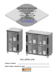
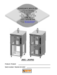
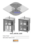
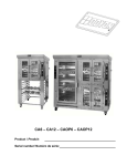
JA6G & JAOP6G
IMPORTANT SAFETY INSTRUCTIONS
SAVE THESE INSTRUCTIONS
TABLE OF CONTENTS
SECTION « A » DESCRIPTION
PAGE
Introduction. . . . . . . . . . . . . . . . . . . . . . . . . . . . . . . . . . . . . . . . . . . . . . . . . A1
Construction . . . . . . . . . . . . . . . . . . . . . . . . . . . . . . . . . . . . . . . . . . . . . . . . A2
Shipping . . . . . . . . . . . . . . . . . . . . . . . . . . . . . . . . . . . . . . . . . . . . . . . . . . . . A2
Installation warnings . . . . . . . . . . . . . . . . . . . . . . . . . . . . . . . . . . . . . . . . . . A3
Distances to respect . . . . . . . . . . . . . . . . . . . . . . . . . . . . . . . . . . . . . . . . . . . A5
Installation . . . . . . . . . . . . . . . . . . . . . . . . . . . . . . . . . . . . . . . . . . . . . . . . . . A6
Operation / instruction for oven and proofer. . . . . . . . . . . . . . . . . . . . . . . . A8
Operation for proofer. . . . . . . . . . . . . . . . . . . . . . . . . . . . . . . . . . . . . . . . . . A10
Trouble shooting . . . . . . . . . . . . . . . . . . . . . . . . . . . . . . . . . . . . . . . . . . . . . A11
Oven maintenance and cleaning . . . . . . . . . . . . . . . . . . . . . . . . . . . . . . . . . A14
For more information, please call our office: . . . . . . . . . . . . . . . . . . . . . . . A15
Optional auto steam injection. . . . . . . . . . . . . . . . . . . . . . . . . . . . . . . . . . . A16
Optional watlow control operation. . . . . . . . . . . . . . . . . . . . . . . . . . . . . . . A17
SECTION « B » DIMENSIONS
JAOP6G . . . . . . . . . . . . . . . . . . . . . . . . . . . . . . . . . . . . . . . . . . . . . . . . . . .
JA6G . . . . . . . . . . . . . . . . . . . . . . . . . . . . . . . . . . . . . . . . . . . . . . . . . . . . .
B1
B4
SECTION « C » BURNER ADJUSTMENTS
NATURAL . . . . . . . . . . . . . . . . . . . . . . . . . . . . . . . . . . . . . . . . . . . . . . . .
PROPANE . . . . . . . . . . . . . . . . . . . . . . . . . . . . . . . . . . . . . . . . . . . . . . . . .
C1
C2
SECTION « E » COMPONENT PARTS
Component parts . . . . . . . . . . . . . . . . . . . . . . . . . . . . . . . . . . . . . . . . . . . .
E1
SECTION « F » CONTROL PANELS
JA6G 120V/1PH/60 Hz . . . . . . . . . . . . . . . . . . . . . . . . . . . . . . . . . . . . . .
JA6G & JAOP6G 120V/208V/1PH & 120V/240V/1PH . . . . . . . . . . . .
JA6G & JAOP6G 120V/208V/3PH & 120V/240V/3PH . . . . . . . . . . . .
JA6G & JAOP6G 220V/1PH/50HZ . . . . . . . . . . . . . . . . . . . . . . . . . . . .
F1
F3
F5
F7
SECTION « G » ELECTRIC SCHEMATICS
JAOP6G 120V/208V/1PH & 120V/240V/1PH . . . . . . . . . . . . . . . . . . .
JAOP6G 120V/208V/3PH & 120V/240V/3PH . . . . . . . . . . . . . . . . . . .
JAOP6G 220V/1PH/50 Hz . . . . . . . . . . . . . . . . . . . . . . . . . . . . . . . . . . .
JA6G 120V/1PH/60 Hz . . . . . . . . . . . . . . . . . . . . . . . . . . . . . . . . . . . . . .
JA6G 120V/208V/1PH & 120V/240V/1PH . . . . . . . . . . . . . . . . . . . . . .
JA6G 120V/208V/3PH & 120V/240V/3PH . . . . . . . . . . . . . . . . . . . . . .
JA6G 220V/1PH/50HZ . . . . . . . . . . . . . . . . . . . . . . . . . . . . . . . . . . . . . .
Warranty . . . . . . . . . . . . . . . . . . . . . . . . . . . . . . . . . . . . . . . . . . . . . . . . . . .
CAUTION
In case of strong gas odors, shut off the gas input valve
and contact a specialised gas technician
FAM6GA.DOC
Rev. 03-12-2001
G1
G2
G3
G4
G5
G6
G7
A1
INTRODUCTION
The manufacturer suggests to read this manual carefully.
This Jet Air gas fired oven is manufactured with first quality material by experienced technicians.
Proper installation and maintenance will guarantee a reliable service for years to come.
A nameplate fixed to the front or right side of the oven specifies the model number, type of
combustible, BTU rating, operating pressures, serial number, voltage and amperage.
Drawings, electrical diagrams and replacement parts numbers are included in this manual. The
electrical diagram is affixed in the control panel at the back of the oven.
ATTENTION
DOYON is not responsible for damages to the property or the equipment caused
by personnel who is not certified by known organisations. The customer is
responsible for finding qualified technicians in gas, electricity and plumbing for
the installation of the oven.
A2
CONSTRUCTION
You just bought the most advanced gas fired oven in the world, "DOYON" technology at its best.
This gas fired oven is manufactured using the highest quality components and material.
The oven gives a perfect uniform baking with its unique Jet Air convection system. The DOYON gas
fired oven is designed with parts that are easy to find.
SHIPPING
For your safety, this equipment has been verified by qualified technicians and carefully crated before
shipment. The freight company assumes full responsibility concerning the delivery in good condition
of the equipment in accepting to transport it.
IMPORTANT
RECEPTION OF THE MERCHANDISE
Take care to verify that the received equipment is not damaged before signing the delivery receipt. If
a damage or a lost part is noticed, write it clearly on the receipt. If it is noticed after the carrier has
left, contact immediately the freight company in order that they do their inspection.
We do not assume the responsibility for damages or losses that may occur during transportation.
A3
INSTALLATION WARNINGS
The DOYON gas fired ovens are designed to be used with the gas specified on the descriptive
nameplate. Refer to National Fuel Gas Code, ANSI-Z223.1-XX and CAN/CGA-B149-XX. Refer to
last edition year for XX. Copies of these are available at:
American Gas Association, 1515 Wilson Boulevard, Arlington, Virginia, 22209.
Association canadienne du gaz, 55 rue Scarsdale, Don Mills, Ontario, Canada, M3B 2R3.
POWER FAILURE WARNING
WHEN YOU HAVE A POWER FAILURE, SHUT OFF THE OVEN POWER SWITCH TO
PROTECT THE ELECTRONIC COMPONENTS WHEN THE POWER COMES BACK.
FOR YOUR SAFETY
DO NOT STORE OR USE GASOLINE OR OTHER FLAMMABLE VAPORS
AND LIQUIDS IN THE VICINITY OF THIS OR ANY APPLIANCE.
INSTALLATION AND SERVICE
WARNING
IMPROPER INSTALLATION, ADJUSTMENT, ALTERATION, SERVICE OR
MAINTENANCE CAN CAUSE PROPERTY DAMAGE, INJURY OR DEATH.
READ THE INSTALLATION, OPERATING AND MAINTENANCE INSTRUCTIONS
THOROUGHLY BEFORE INSTALLING OR SERVICING THIS EQUIPMENT.
Installation and service must be done by specialised technicians. Contact a certified gas technician,
electrician and plumber for set up.
The oven must be connected to the utility and electrically grounded in conformity to the effective
local regulations. If these are not established, the oven must be connected according to the Canadian
Electrical Code (CSA-C22.1- XX) or National Electrical Code (NFPA 70-XX). Refer to last
edition year for XX. Installation must also allow proper access for service (24 inches each side and
back).
The ovens must be installed with a proper ventilation like:
• under a vent hood
• or an exhaust pipe connected directly to the oven chimney flue using the draft hood provided with
the oven.
A4
A type B gas vent approved for use with gas appliances must be utilized.
Make sure that provision for adequate air supply is provided for the operation of the oven.
CAUTION
Make sure that the adjustments mentioned in the "Installation" section are
correctly done prior to firing the oven or converting to a new gas.
A5
DISTANCES TO RESPECT
A)
Back and sides of the oven: 1 inch.
B)
Top of the oven: a clearance of 12 inches to the ceiling must exist to permit adequate venting
of the exhaust pipe and hot parts and to give proper access to a technician. The draft hood
must have a clearance of 2 inches minimum all around.
C)
Floor: 4 inches minimum.
D)
Sides of the oven: do not install other than easily removable equipment for service and
maintenance (not closer than 1 inch).
E)
It is recommended to have a certain length of water pipe, electric cable and gas pipe between
oven and wall to help gain access for service.
A6
INSTALLATION
IN GENERAL
Take off the packaging material with care. Take off all the material used for packing and accessories.
Install the draft hood on the chimney of the oven.
Each unit is set up to be used with the type of gas and electrical supply specified on the nameplate
fixed on the oven.
The installation must be conform with the National fuel gas code ANSI Z223.1-XX and CAN/CGAB149-XX, Gas Installation Code and local Codes where applicable. Refer to last edition year for
XX.
The oven's combustion system consists of a very safe gas burner certified in accordance to the
American Gas Association Standard in USA and with the Canadian Gas Association in Canada.
1. To the certified gas technician
The burner installed on DOYON gas fired ovens is set up and adjusted at the plant for a first
class operation. It is nevertheless necessary to verify on site the pressure at the burner input.
The following table indicates the pressures that must be set up to remain conform to the
A.G.A. standards or C.G.A.
GAS TYPE
Propane
Propane
Natural
Natural
ALTITUDE
(FT)
INPUT
(BTU)
EACH
OVEN
SECTION
REGULATOR
INPUT
PRESSURE
(Water column
inches)
BURNER
INPUT
PRESSURE
(Water column
inches)
BURNER
ORIFICE SIZE
(DMS)
0-2000
2000-4500
0-2000
2000-4500
65 000
65 000
65 000
65 000
11,0
11,0
7.0
7.0
7
7
3.3
3.3
39
39
26
26
The burner used is adjusted to be used with the gas indicated on the nameplate. It is nevertheless
possible to convert the burner to another gas by doing the modifications indicated in the
CONVERSION PROCEDURE provided with the oven. These modifications must be done carefully and
completely under the company's instruction to remain conform to A.G.A. or C.G.A standards. Refer
to Doyon Equipment to get the right CONVERSION KIT.
A7
The installation must be made with a connector that meets with the standard for connectors movable
gas appliances ANSI Z21.69-XX and a Quick-disconnect device that complies with the standard for
Quick-disconnect devices for use with gas fuel ANSI Z21.41-XX and addenda Z21.41a-XX and
Z21.41b-XX. Refer to last edition year for XX. It must also be installed with restraining device
(chain comes with the oven) to guard against transmission of strain to the gas supply and connectors.
The pipe fittings compound must be certified for gas.
The customer must install a manual shut off valve at the end of the gas supply pipe near the burner
which is approved by the American Gas Association Standard in the United States and with the
Canadian Gas Association in Canada.
Exhaust: A draft hood is provided with the unit and it must be used when the chimney is directly
connected to a gas vent pipe. The exhaust pipe must be certified for use of gases.
Clean the air contained in the gas supply pipe at the installation to insure a successful firing on the
first try. The gas pipe sealing compound tightness must be verified using a solution of water and soap
prior to firing the unit.
WARNING
Make sure not to obstruct the overpressure opening on the gas regulator.
NOTE: If there's any modification done to the system or change of the type of gas used,
make sure that the regulator pressure of the burner is adjusted as recommended in this
manual.
2. To the electrician
Electrical supply installation must be in accordance with the electrical rating on the nameplate.
WARNING
The electrician must make sure that the supply cable does not come in contact
with the oven top which becomes hot.
3. To the plumber
This equipment is to be installed to comply with the applicable federal, state or local plumbing codes.
Connect the steam system (1/4 NPT) to the cold water distribution network.
We highly recommend a water softener to eliminate minerals in the water. We suggest you to use
CUNO # CFS6135 (Doyon part number PLF240).
WARNING
Do not adjust the needle valves, it has been done at the factory.
A8
OPERATION OF THE OVEN
1. Turn the switch to the " ON " position.
•
The light inside the oven must light up.
2. Adjust the thermostat at the desired setting (see THERMOSTAT INSTRUCTIONS below).
N.B. The red light must be "ON" (If not, press the breaker on the front).
3. Heat the unit until you reach the baking temperature.
When the desired temperature is reached, the red light goes out and turns green.
If the light is still "ON" and the oven does not produce heat, call for service.
4. Load the oven as fast as possible to avoid letting out too much heat.
5. Set the timer to the desired value and start it. (See "TIMER" adjustment on next page.)
NOTE: The timer does not shut the oven off at the end of its cycle. It simply activates the buzzer.
6. Wait until the product is ready. Do not open the doors until the product is done.
VERY IMPORTANT
This oven has an overheat warning alarm to protect the electrical components against overheating. If
the red pilot light (OVERHEAT WARNING) is lit and you hear a buzzer, see trouble shooting.
THERMOSTAT INSTRUCTIONS
To obtain a very good thermal stability, we use a digital temperature controller with thermocouple.
The Omron E5CS thermostat controls the heat of every element at the SP (set point).
The temperature of the oven is always shown on the display of the thermostat and an arrow indicates
if the temperature is over or below the SP. When the green light is lit, it indicates that the temperature
is at the SP ± 1 %.
To adjust the SP (set point) value, you just have to press the key on the left and use the up and down
keys to set the temperature. Press the left key to return to run mode.
A9
INSTRUCTIONS FOR OVEN
BAKING
350oF (Croissants, Sweet doughs, Small rolls)
375oF (Baguette bread, round loaf, 16 oz. bread and more)
375oF (If the oven is filled to its capacity)
Place product in the oven only when the pilot light has gone out.
OPENING AND CLOSING OF THE DOORS
To open the doors: Open one of the doors up to 2" and wait 2 seconds to let the fan reduce its
spinning before opening completely.
To close the doors: Close the first door completely and the second door down to 2" and wait 2
seconds before closing completely and then hold the door closed for 2 seconds.
P.S.
Open the doors as little as possible. This will affect the baking.
COOKING TIMER H5CL
Set the baking time required with the small push button on the timer. The green display is the setting
time and the red display is the countdown time (Ex: 25 minutes = set 2500 on green display).
After setting: Push the START/STOP button then, when the time expires, the buzzer will ring. Push
the START/STOP button again to stop the buzzer.
If you want to restart the time in the middle of the countdown, press on the yellow RST button on the
timer.
P.S. The timer is simply a reminder for the approximate duration of the baking time.
STEAM TIMER H3DE
VERY IMPORTANT
Steam injection will only work when the ventilator of the oven is working.
To inject steam in the oven, press and release the STEAM TIMER button. The light comes on
inside the steam button during the steam injection. Steam injection has been factory preset. To have
more steam, press steam button a second time, after the light is off.
P.S.
Do not inject steam more than once each time you bake. Wait at least 10 minutes before retiming the steam injection system.
A10
OPERATION OF THE PROOFER
1. Switch "ON".
2. Set the thermostat control at 100o F.
3. Set the humidity control at approximately : 3 for JAOP-3 & JAOP-6
4 or 5 for JAOP-10
5 for JAOP-14
4. If there is too much fog and water drips from the glass doors, adjust humidity control to a lower
number.
5. When the temperature is stabilised, put the products in the proofer.
(Leave them inside until they are ready to bake.)
6. IMPORTANT : When proofing cycle is completed, turn the humidity switch to "OFF" and
let the motor blower and air heat element run for 10-15 minutes to let dry the proofer. Then, turn
the main switch off, and leave the door ajar to prevent moulding.
When the proofer is not in operation, open the doors to let out the humidity, and to prevent
mould.
P.S.
The doors should not be opened unnecessarily to conserve the heat and humidity in the
proofer.
Every day cleaning of the water pan under the proofer's doors should be exercised.
A11
TROUBLE SHOOTING
BEFORE CALLING FOR SERVICE
ANSWERS TO MOST FREQUENT QUESTIONS
Always cut off the main power before replacing any parts. Take care of water and gas
piping system when pulling the oven.
Control parts on the front and proofer Remove the side panels of the oven and the
proofer by screwing out the screws.
control:
Gas and motor system on the back of the Pull the oven and screw out of the panels.
oven:
Questions
Solutions
The oven does not turn on.
Check the breakers on the front panel.
Check the breakers of the building.
Check if the doors are tightly closed.
Check the motor fuses and the overload relays
located in the electrical control panel.
The oven does not produce heat.
• Make sure: the thermostat is adjusted to a
temperature high enough to turn on the pilot
light.
1. If the oven blowers are not on, check the
overload relays located in the control
compartment. If anyone of these is
disengaged, call for a qualified technician.
2. If the oven blowers are on:
• Check that the manual shut-off valve is open
correctly.
To start it over, simply put the thermostat to the
"OFF" position, wait at least 10 seconds, then
reset it at the desired temperature. The burner
will start up and you can see the flame through
the hole near the gas input. You can repeat this
operation three times. If it does not start up
again, contact our company or a certified gas
technician.
A12
• The burner goes to lock-out because of:
a) Flame failure:
b) The spark is irregular or not present:
The burner is equipped with multiple
interlocked safety devices. In the event of a
failure of the flame or any blockage of the
combustion air supply, the burner will "lock
out" in the safety condition.
• Air has not been bled from the gas line.
• Porcelain insulators cracked (very little
crack is enough).
• Spark probe grounded.
• It may be disconnected, incorrectly set or
defective or maybe the blower is not
c) The air pressure switch does not close its
running.
contact.
Make sure that the grills do not obstruct the air
Uneven baking.
flow. Do not use foil on the grills.
Verify the temperature of the oven by using an
oven thermometer and make sure that it is even
with the thermostat setting.
If the oven is baking too much on the sides, it is
possible that the fan is not cycling properly.
(Verify if the motor turns 2.5 minutes in a
direction, stops 30 seconds and starts for 2.5
minutes in the opposite direction.
The steam works in the oven but the light Replace the inside button bulb light.
inside the steam button does not lite.
If steam device of the oven does not work The oven must have been heating for at least
half an hour before you use the steam system. If
properly.
not, water will appear at the bottom of the oven.
Check if the water supply valve (of the
building) is open.
Check if the water needle valve (of the oven) is
open one eighth of a turn. Just close it and open
it one eighth of a turn maximum.
Check the solenoid valve.
Check the preset steam timer in the back
control box.
Be sure to inject steam while the fan is running.
The steam button light should lite during the
steam injection.
A13
If the OVERHEAT WARNING light is on, Check if the cooling fan airflow is not
obstructed.
and you hear the warning buzzer.
Check the cooling fan if it is running. If not,
call a qualified technician to replace it.
(Electrical components may be damaged if it is
not repaired immediately.)
You have no more water in the principal water
OPTIONAL
pan.
Manual fill water pan.
The warning red light in the front control Check if the water line is not in air lock
condition. Disconnect the water line at the inlet
panel stays on when the water pan is full.
of the green solenoid valve and clean the
strainer filter.
Also clean the principal water pan and the float
switch.
1.Verify every breaker in front of the proofer.
If there is no light in the proofer.
2.Verify the main proofer switch and the main
proofer contactor.
1.Verify every breaker in front of the proofer.
If there is no heat in the proofer.
2.Verify whether the pilot light will function by
raising the thermostat to a higher setting. If yes,
verify element. If not, verify pilot light,
thermostat or contactors.
Verify whether the pilot light works when you
If there is no humidity in the proofer.
increase the humidity to the position high. If yes,
verify if water comes in the reservoir and check
the water level switch box and the float switch.
Verify if limestone obstructs the waterflow. If the
float switch is working fine, verify the contactor
P1 and the immersion element. If the pilot light
does not lite, verify the pilot light and the infinite
switch.
Do not allow any obstruction to free the airflow of the burner.
CAUTION
Never try to modify the burner controls. This must be done only by a qualified
technician and under the company's instructions.
A14
OVEN MAINTENANCE AND CLEANING
MAINTENANCE OF THE BURNER
• Once a year, you should ask a certified technician to make a tune up.
Make sure everything works properly, verify and clean especially:
1.
2.
3.
4.
5.
6.
The gas mixer air inlet.
The spark rod and porcelain insulators.
The flame detection rod.
Verify the burner input pressure.
Verify every adjustments.
Clean every moving pieces.
MAINTENANCE OF THE OVEN
• It is recommended to use a water filter and to clean or replace it regularly to avoid
accumulation of minerals inside the unit.
• Once a year or as needed, clean the reservoir of the proofer (see parts description for
localization).
Step by step
Recommendations
Clean the inside of the oven and the proofer We recommend and sell:
Dirt Buster III : Action foam cleaner
with water and soap.
CHEMCO
Take out the grills (the grills of the oven Part number : NEB201
could be cleaned with "Easy-Off").
After cleaning the inside of the oven, apply a We recommend and sell:
silicone base oven protector. It avoids food 316 Silicone base protector and lubricant for
oven
from sticking to the metal.
Dow Corning
Part number : EXS400
Clean the oven windows with products like We recommend and sell:
Brasso or equivalents. They are copper Wright's: Cream copper cleaner
J.A. Wright & Co.
cleaners but good for this use.
Part number : EXC300
Clean the oven exterior with a stainless steel We recommend and sell:
Stainless steel cleaner
cleaner.
SANY or CURTIS (comestible)
Part number : NES201
A15
FOR MORE INFORMATION,
PLEASE CONTACT OUR OFFICE:
DOYON EQUIPMENT INC.
1255, rue Principale
Linière, Qc, Canada G0M 1J0
Tel. : 1 (418) 685-3431
Canada : 1 (800) 463-1636
U.S. : 1 (800) 463-4273
FAX : 1 (418) 685-3948
Internet: http://www.doyon.qc.ca
E-Mail : [email protected]
A16
AUTOMATIC STEAM OPTION
INTERVALS TIMES SETTING (GREEN)
INJECTION TIMES SETTING (RED)
INTERVALS MULTIPLICATOR SETTING
STEAM INJECTION MULTIPLICATOR SETTING
SCALE ADJUSTMENT
By pushing the GREEN button, the button will light up and the automatic system injection will
start. The injection will be done as per the pre-adjustment time on the automatic steam timer. The
standard steam timer (white light) will light up during the steam injection. Push the RED button
to stop the automatic steam injection and then, the GREEN button will turn off.
Timer adjustments
EXAMPLE : For 5 seconds of steam injection every 10 minutes : Set the interval multiplicator screw
(OFF) at MIN and the GREEN needle at 10. Set the injection multiplicator screw (ON) at SEC and
the RED needle at 5.
EXAMPLE : For 2 seconds of steam injection every 25 seconds : Set the interval multiplicator screw
(OFF) at SEC and the GREEN needle at 25. Set the injection multiplicator screw (ON) at SEC and
the RED needle at 2.
A17
WATLOW CONTROL OPERATION
1. Turn the switch to the " ON " position. (See next paragraph for the factory-preset program on your
watlow control).
•
The light inside the oven must light up.
2. Adjust the WATLOW control at the desired setting (see watlow programming procedure next
page).
Digital display must light up, if not, verify the breaker on the front panel.
3. Let the oven heat until the set temperature is reached, the LOAD1 red light on the watlow control
will go off when the temperature is stabilized.
4. Load the oven as fast as possible to avoid letting out too much heat.
5. Wait until the product is ready before opening doors.
FACTORY PRESET BAKING PROGRAM
MENU # 1 PREHEAT 400°F.
MENU # 2 375°F STEAM 15 SEC., COOKING TIMES 22 MINUTES WITH BUZZER
MENU # 3 350°F STEAM 15 SEC., COOKING TIMES 25 MINUTES WITH BUZZER.
MENU # 4 325°F NO STEAM, COOKING TIMES 25 MINUTES WITH BUZZER.
325°F (Muffins)
350°F (Croissants, Sweet Doughs, Small rolls)
375oF (Baguette bread, round loaf, 16 oz. bread and more)
375oF (If the oven is filled to its capacity)
OPENING AND CLOSING OF THE DOORS
To open the doors: Open one of the doors up to 2" and wait 2 seconds to let the fan reduce its
spinning before opening completely.
To close the doors: Close the first door completely and the second door down to 2" and wait 2
seconds before closing completely and then hold the door closed for 2 seconds.
P.S.
Open the doors as little as possible. This will affect the baking.
POWER FAILURE
When the power comes back, the oven will start automatically on the menu #1. Then it is
recommended to turn off the oven to avoid that it starts without supervision.
A18
WATLOW PROGRAMMING
The Watlow temperature control can record 12 different menus. It must be programmed before use.
It will save its programs in case of power failure.
Each menu includes 3 "STEPS" and each step includes :
Symbol
• temperature
• time
• "EVENT"
SP
t
E
(steam 0001, auto steam 0100, buzzer 0010 or
no event 0000)
To access the programming mode :
• Press both arrows simultaneously for 5 seconds. Both lights light up to show that the
programming mode is working.
• Unlock the read only mode (if necessary), press 12 and "CLOCK", LOC appears. Use the arrows
to get 0 and press "CLOCK" again. (To put back on read only mode, you have to have 1 before
pressing on "CLOCK".)
EXAMPLE 1 (preheat program)
-
For menu #1, we will program it so that we have a preheat time of 20 minutes at 400°F followed
by a 15 seconds buzzer.
Step #1
• Press both arrows simultaneously for 5 seconds. Both lights light up to show that the
programming mode is working.
• Select the program number (Ex : #1)
Suggested values
SP1 appears.
Use the arrows to adjust to the desired temperature
Press on the number of the menu to confirm
(400°F)
(ex. # 1)
t1 appears
Use the arrows to select the desired timing
Press on the number of the menu to confirm
(20:00)
(ex. # 1)
E1 appears
Use the arrows to select the appropriate code
Press on the number of the menu to confirm
Step #2
(0000 for no event)
(ex. # 1)
Suggested values
A19
SP2 appears.
Use the arrows to adjust to the desired temperature
Press on the number of the menu to confirm
(400°F)
(ex. # 1)
t2 appears
Use the arrows to select the desired timing
Press on the number of the menu to confirm
(00:15)
(ex. # 1)
E2 appears
Use the arrows to select the appropriate code
Press on the number of the menu to confirm
(0010 for buzzer)
(ex. # 1)
Step #3
Suggested values
SP3 appears.
Use the arrows to adjust to the desired temperature
Press on the number of the menu to confirm
(400°F)
(ex. # 1)
t3 appears
Use the arrows to select the desired timing
Press on the number of the menu to confirm
(00:01)
(ex. # 1)
E3 appears
Use the arrows to select the desired code
Press on the number of the menu to confirm
(0000 for no event)
(ex. # 1)
To get out of the programming mode, press #12 and then press "CLOCK" twice (#12, CLOCK,
CLOCK). The screen will show 00:00.
Note: You should always use menu #1 for preheating because the controls starts automatically with
this menu.
WARNING
Never use program #1 for a steam cycle because it will start automatically when the oven is
turned on.
A20
EXAMPLE 2 (Cooking program with steam cycle)
-For menu #2, we will program it so that we have a steam injection of 20 seconds, a cooking time of
20 minutes at 375°F followed by a 15 seconds buzzer.
To access the programming mode:
• Press both arrows simultaneously for 5 seconds. Both lights light up to show that the
programming mode is working.
• Select the menu number (Ex. #2)
Step #1
Suggested values
SP1 appears.
Use the arrows to adjust to the desired temperature
Press on the number of the menu to confirm
(375°F)
(ex. # 2)
t1 appears
Use the arrows to select the desired timing
Press on the number of the menu to confirm
(00:20)
(ex. # 2)
E1 appears
Use the arrows to select the appropriate code
Press on the number of the menu to confirm
(0001 for the steam)
(ex. # 2)
Step #2
Suggested values
SP2 appears.
Use the arrows to adjust to the desired temperature
Press on the number of the menu to confirm
(375°F)
(ex. # 2)
t2 appears
Use the arrows to select the desired timing
Press on the number of the menu to confirm
(20:00)
(ex. # 2)
E2 appears
Use the arrows to select the appropriate code
Press on the number of the menu to confirm
(0000 for no event)
(ex. # 2)
A21
Step #3
Suggested values
SP3 appears.
Use the arrows to adjust to the desired temperature
Press on the number of the menu to confirm
(375°F)
(ex. # 2)
t3 appears
Use the arrows to select the desired timing
Press on the number of the menu to confirm
(00:15)
(ex. # 2)
E3 appears
Use the arrows to select the desired code
Press on the number of the menu to confirm
(0010 for the buzzer)
(ex. # 2)
To get out of the programming mode, press #12 and then press "CLOCK" twice (#12, CLOCK,
CLOCK). The screen will show 00:00.
After fulfillment of this program:
• The oven will continue to heat because there was a temperature included in step 3. If the
temperature at that step would have been of 0°F, the oven would have stopped at the end
of the program.
• In this example, the inside buzzer will work 15 seconds while the outside buzzer will start
and will not stop until another program is selected.
• If you want to end a program already running, press the button corresponding to that menu
and then choose a pause menu. If you stop a program that was running without choosing
another menu, it will be paused in the conditions in which it was stopped. Ex: If there is an
interruption during a steam cycle, it will keep running until you choose another menu.
However, there is a 45 seconds limit time for the steam, independent from the Watlow
controller.
SECTION
B
DIMENSIONS
B1
JAOP6G
36 1/2
20
BAKING TIMER
THERMOSTAT
81 1/2
72 3/4
OVEN
INTERIOR DIMENSIONS
26 1/4"
HEIGHT
25 1/2"
WIDTH
29 1/2"
DEPTH
PROOFER
INTERIOR DIMENSIONS
26 1/2"
HEIGHT
26 1/2"
WIDTH
36 1/2"
DEPTH
JAOP6G
B2
52 3/4
JAOP6G
24 3/8
JAOP6G
B3
JAOP6G
20
ENTRÉE DE GAZ Ø1/2 NPT
GAS INLET Ø1/2 NPT
ENTRÉE D’EAU Ø1/4 NPT
WATER INLET Ø1/4 NPT
ENTRÉE ÉLECTRIQUE
ELECTRICAL INLET
59
46 1/4
JAOP6G
B4
JA6G
36 1/2
20
9
BAKING TIMER
43 3/4
THERMOSTAT
34 3/4
OVEN
INTERIOR DIMENSIONS
26 1/4"
HEIGHT
25 1/2"
WIDTH
29 1/2"
DEPTH
38
35 7/8
JA6G
B5
41 3/4
JA6G
52 3/4
16 1/2
63
46
JA6G
37 7/8
B6
JA6G
PANNEAU ÉLECTRIQUE
ELECTRICAL PLANEL
ENTRÉE DE GAZ 1/2" NPT
GAS INLET 1/2" NPT
ENTRÉE D’EAU 1/4" NPT
WATER INLET 1/4" NPT
JA6G
ENTRÉE ÉLECTRIQUE
ELECTRICAL INLET
SECTION
C
BURNER ADJUSTMENTS
JA6G−P
SUPPLY PRESSURE: 11" W.C. (28/50 Mbar)
MANIFOLD PRESSURE: 7" W.C. (17.50 Mbar)
IGNITION WIRE: 13"
DETECTION WIRE: 16"
HIGH LIMIT: 700° F
LOCKED: 600° F
THERMOSTAT: OMRON E5CS−X
BTU: 65 000
NOZZLE #39
(2.5mm)
2
SPACER
#31 (3.0mm)
1 1/2
[38.15]
1
PROTECTOR FOR
MINERAL WOOL
1 1/2
[38.10]
5/32
[3.98]
INSULATION
COMBUSTION−CHAMBER
GROUND PLATE
2 3/8
[60.33] 5/32
[3.97]
NOZZLE
2 9/16
[65.09]
PIECE #2
THICKNESS 1/8 (3.2mm)
COMBUSTION−CHAMBER
PIECE #1
THICKNESS 3/32 (2.4mm)
4 HOLES Ø7/16 [Ø11.10]
ON Ø1 5/8 [Ø41.27]
C1
ADJUSTMENT BURNER
JA6G PROPAN GAS
JA6G−N
SUPPLY PRESSURE: 7" W.C. (20/25 Mbar)
MANIFOLD PRESSURE: 3.3" W.C. (8.25 Mbar)
IGNITION WIRE: 13"
DETECTION WIRE: 16"
HIGH LIMIT: 700° F
LOCKED: 600° F
THERMOSTAT: OMRON E5CS−X
BTU: 65 000
NOZZLE #26
(3.7mm)
2
SPACER
#29 (3.5mm)
1 1/2
[38.15]
1
PROTECTOR FOR
MINERAL WOOL
1 1/2
[38.10]
5/32
[3.98]
INSULATION
COMBUSTION−CHAMBER
GROUND PLATE
2 3/8
[60.33] 5/32
[3.97]
NOZZLE
2 9/16
[65.09]
PIECE #2
THICKNESS 1/8 (3.2mm)
COMBUSTION−CHAMBER
PIECE #1
THICKNESS 3/32 (2.4mm)
4 HOLES Ø5/16 [Ø7.94]
ON %%1 5/8 [Ø41.28]
4 HOLES Ø7/16 [Ø11.10]
ON %%1 5/8 [Ø41.28]
C2
ADJUSTMENT BURNER
JA6G NATURAL GAS
SECTION
E
COMPONENT PARTS
E1
JAOP6G
1
BAKING TIMER
3
18
THERMOSTAT
5
17
6
7
16
11
15
13
14
JAOP6G
E2
Item
1
2
&
&
3
&
&
4
&
5
&
&
6
&
7
8
9
AND
AND
10
AND
OR
AND
11
OR
12
13
14
AND
15
16
AND
17
18
AND
Part Number
ELM760
ELM616
ELM629
ELM726
ELP994
ELI554
ELI555
ELT515
ELT522
ELL775
ELL756
ELL645
ELI550
ELI555
ELB096
ELL650
ELT627
ELT628
ELT620
ELI220
ELI240
ELI230
ELI240
QUP460
QUP465
ELB097
QUA200
PAR800
PAR850
P1428EG
P1428ED
QUE500
P1428FG
P1428FD
QUE500
Model : JAOP6G
Description
COOLING FAN 120VOLTS
ELECTRONIC TIMER OMRON H5CX-L8
ELECTRONIC TIMER 8 PIN SOCKET
PANEL MOUNTING
PUSH-BUTTON (BLACK)
MECHANICAL HOLD (ON-OFF) CONTACT
CONTACT BLOCK 1NO
ELECTRONIC THERMOSTAT
THERMOCOUPLE J TYPE
HIGHLITED PUSH BUTTON SOCKET WHITE
PUSH BUTTON SOCKET (N.O.)
MINIATURE LAMP 3 WATTS 130 VOLTS
MAIN SWITCH
(SELECTOR)
CONTACT BLOCK 1NO
5A BREAKER
RED PILOT LIGHT
THERMOSTAT 110F
THERMOSTAT KNOB 110F
THERMOSTAT BEZEL
INFINITY SWITCH 120V (HUMIDITY CONT.)
INFINITY SWITCH KNOB
INFINITY SWITCH 240V (HUMIDITY CONT.)50Hz)
INFINITY SWITCH KNOB
DOOR HANDLE (BLACK)
DOOR HANDLE STAINLESS TUBING
20A BREAKER
DOOR MAGNET
SWIVEL CASTER
SWIVEL CASTER WITH BRAKE
LEFT DOOR FOR PROOFER 14 1/4"X28 3/4"
RIGHT DOOR FOR PROOFER 14 1/4"X28 3/4"
DOOR GASKET(10`)
LEFT DOOR FOR OVEN 14 1/4" X 28 3/4"
RIGHT DOOR FOR OVEN 14 1/4" X 28 3/4"
DOOR GASKET(10`)
View:FRONT
Quantity
1
1
1
1
1
1
1
1
1
1
1
1
1
1
1
3
1
1
1
1
1
1
1
4
4
2
8
2
2
1
1
1
1
1
1
E3
JAOP6G
10
6
5
4
3
X4
X2 X3 X1
X4 X2 X3 X1
H1 H3 H2 H4
H1 H3 H2 H4
11
2
12
7
1
8
9
JAOP6G
E4
Item
1
2
3
4
5
6
AND
7
AND
8
9
10
AND
11
AND
12
AND
Part Number
ELE165
ELE130
ELM730
ELM570
ELS950
ELD050
ELA275
ELC615
ELC617
ELS880
QUF350
ELT507
ELT503
ELT712
ELT715
ELC630
ELC640
Model : JAOP6G
Description
IMMERSION ELEMENT 120V 1500W
COIL ELEMENT 120V 1500W
PROOFER FAN BLOWER
DOOR SWITCH
BUZZER 120V
INCANDESCENT LIGHT SOCKET
BULB 60W 130V
RELAY 10A 2P COIL 110V
BASE
SOLENOID VALVE 110/120V 50/60Hz
ELECTRIC FLOAT
HIGH LIMIT THERMODISC SWITCH 110°F
HIGH LIMIT SWITCH 140°F
TRANSFORMER 240/120 50VA(MOD. 220 V ONLY)
TRANSFORMER 240>120 100VA(MOD. 220 V ONLY)
CONTROL RELAY 12A COIL 120V
CONTROL RELAY BASE
Quantity
1
1
1
1
1
5
5
1
1
1
1
1
1
1
1
1
1
View : SIDE
E5
JAOP6G
10
9
11
7
4
3
12
2
1
JAOP6G
0
25
350
5
45
0
6
550
150
OFF
8
E6
Item
1
OR
2
3
4
AND
5
6
AND
Part Number
ELP850
ELP895
GAT100
GAB500
GAD200
GAD190
GAM200
GAC240
GAC241N
GAC241P
7
ELT680
AND ELT681
AND ELT620
8
ELM800ML
OR ELM820ML
9
ELS880
10 PLF100
11 ELV590
12 GAP300
Model : JAOP6G
Description
CONTROL PANNEL 240V 1PH SINGLE
CONTROL PANEL 208 3 PH GAS SINGLE
TRANSFORMER 120/25V 20VA.
ELECTRONIC CONTROL WITH ALARM CONTACT
FLAME DETECTION ROD
IGNITION ROD
ATMOSPHERIC MIXER
NATURAL GAS VALVE #VR8305M2102B
NATURAL GAS PRESSURE REGULATOR
PROPANE GAS PRESSURE REGULATOR
THERMOSTAT 700°F
THERMOSTAT KNOB 700°F
THERMOSTAT BEZEL
MOTOR 1 PH. 3/4 HP.MAGNETEK WITH 6 1/4 INCHES SHAFT.
MOTOR 3 PH. 3/4 HP. MAGNETEK WITH 6 1/4 INCHES SHAFT.
SOLENOID VALVE 110/120V 50/60Hz
WATER FILTER
NEEDLE VALVE
PRESSURE SWITCH
Quantity
1
1
1
1
1
1
1
1
1
1
1
1
1
1
1
1
1
2
1
View : BACK
SECTION
F
CONTROL PANELS
120 VOLTS
1 PHASE
SIMPLE − JA − GAS
8
9
10
11
12
34 5 67
H3DE−M1
1
2
1
9
8
10
2
1
0
SEC
3
7
4
5
6
F1
P120JA6G
F2
Item
1
2
3
OR
4
OR
5
OR
6
7
8
9
10
Part Number
ELB071
ELL050
ELC495
ELC505B
ELC515
ELC520
ELO125
ELO220
ELO100
ELO210
ELM715
ELB073
ELF975
ELF830
ELM614
Description
TERMINAL BLOCK 2P 175A
GROUND LUG
MOTOR REVERSING CONTACTOR 2HP(TELEMECANIC)
CONTACTOR COIL (ONLY)(TELEMECANIC)
MOTOR REVERSING CONTACTOR 2HP(SPRECHER)
CONTACTOR COIL (ONLY)(SPRECHER)
OVERLOAD BASE RELAY(TELEMECANIC)
OVERLOAD RELAY BASE(SPRECHER)
OVERLOAD 7 TO 10 Amps.(TELEMECANIC)
OVERLOAD 6 - 9.5 Amps.(SPRECHER)
PRESET TIMER 25SEC. OFF - 150SEC. ON
TERMINAL BLOCK 30A
FUSE HOLDER 30A 250V 1P
FUSE 15A 250V
OMRON STEAM TIMER H3DE
Model : JA-6G 120 VOLTS
Quantity
1
2
1
1
1
1
1
1
1
7
1
1
1
View : INSIDE (See OVEN BACK)
240 VOLTS
1 PHASE
SIMPLE − JAOP − GAS
8
9
10
11
12
3 4 5 67
P240S−G1
8
9
10
11
7
H3DE−M1
1
2
1
0
SEC
6
1
5
2
3
4
F3
F4
Item
1
2
2
3
4
5
6
7
8
9
10
11
Part Number
ELC495
ELC505B
ELO098
ELO098
ELO125
ELM715
ELB073
ELF970
ELF820
ELB072
ELL050
ELC860
ELM614
Description
MOTOR REVERSING CONTACTOR 2HP
CONTACTOR COIL (ONLY)
OVERLOAD TELEMECANIQUE 2.5 TO 4 AMPS
OVERLOAD 2.5 - 4 Amps.
OVERLOAD BASE RELAY
PRESET TIMER 25SEC. OFF - 150SEC. ON
TERMINAL BLOCK 30A
FUSE HOLDER 30A 250V 2P
FUSE 8A 250V
TERMINAL BLOCK 3P 175A
GROUND LUG
CONTACTOR 2P 30A 110V(PROOFER ONLY)
OMRON STEAM TIMER H3DE
Model : 240V 1PH JAOP-G
Quantity
1
1
1
1
1
1
8
1
2
1
2
1
1
View : PANEL
208 VOLTS
3 PHASES
SIMPLE − JAOP − GAS
2
H3DE−M1
SEC
1
3
P208S−G1
9
10
3 4 5 67
2
8
1
9
0
10
11
12
4
1
5
6
7
8
F5
F6
Item
1
2
3
4
4
5
6
7
8
9
10
Part Number
ELF995
ELF820
ELB071
ELO098
ELO098
ELC495
ELC505B
ELB073
ELL050
ELM715
ELC860
ELM614
Description
FUSEHOLDER 30A 250V 3P
FUSE 8A 250V
TERMINAL BLOCK 2P 175A
OVERLOAD TELEMECANIQUE 2.5 TO 4 AMPS
OVERLOAD 2.5 - 4 Amps.
MOTOR REVERSING CONTACTOR 2HP
CONTACTOR COIL (ONLY)
TERMINAL BLOCK 30A
GROUND LUG
PRESET TIMER 25SEC. OFF - 150SEC. ON
CONTACTOR 2P 30A 110V(PROOFER ONLY)
OMRON STEAM TIMER H3DE
Model : 208V 3PH JAOP-G
Quantity
1
3
2
1
1
1
5
2
1
1
1
View : PANEL
220 VOLTS
1 PHASE
SIMPLE − JAOP − GAS
7
8
9
10
11
12
3 4 5 67
H3DE−M1
1
P220S−G1
9
10
11
8
12
2
1
0
SEC
6
1
2
5
3
4
F7
F8
Item
1
Part Number
ELC495
ELC505B
2
ELO098
2
ELO098
3
ELO125
4
ELM715
5
ELC640
AND ELC630
6
ELB073
7
ELF975
8
ELF820
9
ELB071
10 ELL050
11 ELC860
12 ELM614
Model : P220S-G1
Description
MOTOR REVERSING CONTACTOR 2HP
CONTACTOR COIL (ONLY)
OVERLOAD TELEMECANIQUE 2.5 TO 4 AMPS
OVERLOAD 2.5 - 4 Amps.
OVERLOAD BASE RELAY
PRESET TIMER 25SEC. OFF - 150SEC. ON
CONTROL RELAY BASE
CONTROL RELAY 12A COIL 120V
TERMINAL BLOCK 30A
FUSE HOLDER 30A 250V 1P
FUSE 8A 250V
TERMINAL BLOCK 2P 175A
GROUND LUG
CONTACTOR 2P 30A 110V(PROOFER ONLY)
OMRON STEAM TIMER H3DE
Quantity
1
1
1
1
1
1
1
1
8
1
1
1
2
1
1
View : PANEL
SECTION
G
ELECTRIC SCHEMATICS
G1
ST
L1 L2
OVEN
SWITCH
5 A.
AV−M1
THERMOSTAT
OL1
95
96
7
8
9
10
M1−A
M1−B
7
2
P.L.
PROOFER
SWITCH
ELECT.
GAS
VALVE
120/24
8
1
BULB
TR
BURNER
M
COOKING
SWITCH
4
6
TH
V
24V
IGNITION
V
BOX
24V
GRND
COOKING TIMER
H5CX (MODE A−1)
(ALARM)
COOLING
FAN
PRESSURE HIGH
SWITCH
LIMIT
AR−M1
HIGH
LIMIT
140°
HIGH
LIMIT
110°
BUZZER
N
SPARKING DETECTION
ELECTRODE FLAME ROD
VA
STEAM
SWITCH
STEAM TIMER
H3DE
B1
BUZZER
15
A1
C2
18
A2
TV
VL
OVEN
VALVE
MODE E
C2
20 A.
20 A.
P1
LIQUID
LEVEL
8
R1
7
7
P1
2
F1 F2
INFINIT
SWITCH
5
R1
P
3
BULB
L2 T2
OL1
L1 T1
PILOT
LIGHT
5
H1
1.5 KW
HEAT
PILOT
LIGHT
1.5 KW
HUMIDITY
H2
T1
T4
L3 T3
L2 T2
8
4
L1
L2
T5
L3 T3
M1
FAN
PROOFER
VALVE
AV
L1 T1
1
AR
L1 T1
OVEN
BLOWER
3/4HP
T2 T3
T8
L2 T2
VA
L3 T3
DOOR
SWITCH
ELECTRONIC
TIMER
2
1
N1
A2
A2
M1
AV
M1
AR
A1
AR
4
A1
ST
3
AV
120 / 208 13.5A 17.0A 14.0A
JAOP6 GAS 1 PHASE 60 Hz
120 / 240 13.5A 17.0A 14.0A
8/07/05
TOTAL POWER: 4.0 Kw
60 Hz
4&5
M. FAUCHER
STANDARD
7
1/1
JAOP6G_1
G2
ST
L1 L2 L3
OVEN
SWITCH
5 A.
7
8
9
10
HIGH
LIMIT
140°
COOLING
FAN
P.L.
PROOFER
SWITCH
M1−A
M1−B
PRESSURE HIGH
SWITCH
LIMIT
AR−M1
ELECT.
GAS
VALVE
120/24
7
2
8
1
VA
STEAM
SWITCH
STEAM TIMER
H3DE
B1
BUZZER
15
A1
BULB
C2
TR
BURNER
M
COOKING
SWITCH
4
6
TH
V
24V
IGNITION
V
BOX
24V
GRND
COOKING TIMER
H5CX (MODE A−1)
(ALARM)
HIGH
LIMIT
110°
AV−M1
THERMOSTAT
OL1
95
96
BUZZER
N
SPARKING DETECTION
ELECTRODE FLAME ROD
VL
18
A2
TV
OVEN
VALVE
MODE E
C2
20 A.
20 A.
P1
LIQUID
LEVEL
8
R1
7
7
P1
2
F1 F2 F3
M1
INFINIT
SWITCH
R1
5
P
3
L1
BULB
FAN
PROOFER
VALVE
AV
L1 T1
OL1
L1 T1
L2 T2
L2 T2
L3 T3
L3 T3
L2
1
4
8
5
H1
PILOT
LIGHT
1.5 KW
HEAT
PILOT
LIGHT
1.5 KW
HUMIDITY
H2
OVEN
BLOWER
3/4HP
AR
L1 T1
VA
L2 T2
L3 T3
DOOR
SWITCH
ELECTRONIC
TIMER
2
1
N1
A2
A2
M1
AV
M1
AR
A1
AR
4
A1
ST
3
AV
120 / 208 13.5A 15.0A 13.5A 2.0A
JAOP6 GAS 3 PHASES 60 Hz
120 / 240 13.5A 15.0A 13.5A 2.0A
08/07/04
TOTAL POWER: 4.1 Kw
60 Hz
5
M. FAUCHER
STANDARD
7
1/1
JAOP6G_3
G3
ST
L1
N
TR1
100 VA
120−240V>
120−240V
5 A.
H1
OL1
95
96
7
X2
H4
X4
M1−A
M1−B
AR−M1
10
DETECTION
FLAME ROD
SPARKING
ELECTRODE
HIGH
LIMIT
AV−M1
PRESSURE
SWITCH
120/24
24V
24V
COOKING TIMER
H5CX (MODE A−1)
HIGH
LIMIT
140°
7
2
BULB
8
1
6
4
VA
M
COOKING
SWITCH
STEAM TIMER
H3DE
STEAM
SWITCH
B1
BUZZER
15
18
A1
A2
VL
OVEN
VALVE
TV
MODE E
C2
TR2
50 VA
120−240V>
120−240V
5
X3
H2
X2
P1
LIQUID
LEVEL
2 A.
X1
H3
H4
TR
BURNER
P.L.
H1
TH
GRND
BUZZER
COOLING
FAN
20 A.
ELECT.
GAS VALVE
IGNITION
BOX VALVE
VALVE
HIGH
LIMIT
110°
X3
H2
8
9
(ALARM)
PROOFER
SWITCH
5 A.
THERMOSTAT
X1
H3
OVEN
SWITCH
OVEN
SWITCH
3
C2
8
R1
7
R1
INFINIT
SWITCH
7
P1
PROOFER
VALVE
P
2
H1
L1
FAN
L2
X4
1
4
8
5
1.5 KW
HEAT
PILOT
LIGHT
PILOT
LIGHT
1.5 KW
HUMIDITY
H2
BULB
F1
AV
OL1
L1
T1
L1
T1
L2
T2
L2
T2
L3
T3
T1
L3
T4
T3
3/4HP
MOTOR
T2
AR
T1
L2
T2
L3
T3
50 VA
240−480V>
120−240V
H1
X1
H1
H3
X3
H3
X3
H2
X2
H2
X2
H4
X4
H4
X4
X1
T5
M1
L1
100 VA
240−480V>
120−240V
T8
T3
ALTERNATE TRANSFORMER
ALTERNATE TRANSFORMER
OVEN
PROOFER
VA
DOOR
SWITCH
ELECTRONIC
TIMER
2
1
N1
M1
A1
AV
AR
A2
4
M1
A1
AR
ST
3
AV
A2
JAOP6 GAS 1 PHASE 50 Hz
220
15.0A 15.0A
TOTAL POWER: 3.3 Kw
08/07/04
50 Hz
5
M. FAUCHER
STANDARD
5
1/1
JAP6G1R1
G4
N L1
ST
AV−M1
OVEN
SWITCH
5 A.
THERMOSTAT
OL1
95 96
7
8
9
10
M1−A
M1−B
PRESSURE
SWITCH
SPARKING DETECTION
ELECTRODE FLAME ROD
HIGH
LIMIT
120/24V
AR−M1
24V VALVE
VALVE
GND
HIGH
LIMIT
110°
(ALARM)
P.L.
F1
L1
AV
7
2
BULB
8
6
T2
L3
T3
L2
STEAM
SWITCH
1
4
BUZZER
M
COOKING
SWITCH
B1
TV
BURNER
VA
STEAM TIMER
H3DE
15 18
VL
A1
A2
OVEN
VALVE
MODE E
T3
OL1
L1
T1
L2
IGNITION
CONTROL
COOKING TIMER
H5CX (MODE A−1)
BUZZER
COOLING
FAN
HIGH
LIMIT
140°
ELECT.
GAS VALVE
TH
TR
24V
T1
T1
L3
T2
T3
T1
M−1
3/4HP
MOTOR
T5
T8
M1
L1
AR
T1
L2
T2
L3
T3
T2
T4
VA
DOOR
SWITCH
T2
ELECTRONIC
TIMER
2
ST
1
N1
A1
A1
M1
AV
M1
AR
A2
AR
4
A2
3
AV
JA6 GAS 120V 1 PHASE 60 Hz
120
10A
10A
TOTAL POWER: 1.2 Kw
15/06/04
60 Hz
5
M. FAUCHER
STANDARD
3
1/1
JA6G120
G5
N
L1
L2
ST
OVEN
SWITCH
5 A.
7
8
9
10
M1−A
COOLING
FAN
F1 F2
7
2
BULB
BUZZER
P.L.
ELECT.
GAS VALVE
120/24V
AR−M1
24V
VALVE
TH
24V
VALVE
GRND
TR
IGNITION
CONTROL
COOKING TIMER
H5CX (MODE A−1)
HIGH
LIMIT
140°
8
6
DETECTION
FLAME ROD
M1−B
(ALARM)
HIGH
LIMIT
110°
THERMOSTAT
OL1
95
96
SPARKING
ELECTRODE
HIGH
LIMIT
PRESSURE
SWITCH
AV−M1
VA
STEAM
SWITCH
1
STEAM TIMER H3DE
B1
M
COOKING
SWITCH
4
BURNER
15
18
A1
A2
TV
BUZZER
VL
OVEN
VALVE
MODE E
OL1
AV
L1
T1
L1
T1
L2
T2
L2
T2
L3
T3
T1
L3
T3
T4
3/4HP
MOTOR
T5
C
M1
T2
AR
L1
T1
L2
T2
L3
T3
VA
DOOR
SWITCH
ELECTRONIC
TIMER
2
1
N1
A1
A1
M1
AV
M1
AR
A2
ST
AR
4
A2
T8
T3
3
AV
120 / 208
1.0A
5.0A
4.0A
120 / 240
1.0A
5.0A
4.0A
TOTAL POWER: 1.2 Kw
JA6 GAS 1 PHASE 60 Hz
07/07/04
60 Hz
5
M. FAUCHER
STANDARD
5
1/1
JA6G_1
G6
N
L1
L2
ST
L3
THERMOSTAT
OL1
95
96
7
8
9
10
M1−A
F1 F2 F3
BULB
VALVE
TH
24V
VALVE
GRND
TR
BURNER
VA
STEAM
SWITCH
STEAM TIMER H3DE
B1
M
COOKING
SWITCH
4
6
2
24V
IGNITION
CONTROL
1
8
7
BUZZER
P.L.
120/24V
AR−M1
COOKING TIMER
H5CX (MODE A−1)
HIGH
LIMIT
140°
COOLING
FAN
ELECT.
GAS VALVE
M1−B
(ALARM)
HIGH
LIMIT
110°
PRESSURE HIGH
SWITCH LIMIT
AV−M1
OVEN
SWITCH
5 A.
SPARKING DETECTION
ELECTRODE FLAME ROD
15
18
A1
A2
TV
BUZZER
VL
OVEN
VALVE
MODE E
AV
OL1
L1
T1
L1
T1
L2
T2
L2
T2
L3
T3
T1
L3
T3
T4
3/4HP
MOTOR
T5
C
M1
T2
AR
L1
T1
L2
T2
L3
T3
T8
T3
VA
WARNING
FOR SUPPLY SYSTEMS CONSISTING OF A DELTA
SECONDARY TRANSFORMER, MAKE SURE THAT
THE PHASE FEEDER WITH THE HIGHEST VOLTAGE
(HIGH LEG) IS CONNECTED TO L3 IN THE SUPPLY
BOX OF THIS OVEN (120 / 240V. 3 PH. SYSTEMS).
DOOR
SWITCH
ELECTRONIC
TIMER
2
ST
1
N1
A1
A1
M1
AV
M1
AR
A2
AR
4
A2
3
AV
120 / 208
1.0A
4.0A
3.0A
3.0A
120 / 240
1.0A
4.0A
3.0A
3.0A
TOTAL POWER: 1.2 Kw
60 Hz
JA6 GAS 3 PHASES 60 Hz
07/07/04
5
M. FAUCHER
STANDARD
5
1/1
JA6G_3
G7
L1
ST
N
AV−M1
100 VA
120−240V>
120−240V
5 A.
H1
X1
H3
X3
H2
X2
H4
5 A.
THERMOSTAT
OL1
95
96
HIGH
LIMIT
110°
(ALARM)
OVEN
SWITCH
OVEN
SWITCH
7
BULB
2
BUZZER
COOLING
FAN
8
9
10
M1−A
8
1
6
4
PRESSURE
SWITCH
M1−B
SPARKING
ELECTRODE
DETECTION
FLAME ROD
ELECT.
GAZ VALVE
120/24V
M
COOKING
SWITCH
24V
VALVE
TH
IGNITION
VALVE
BOX
TR
24V
BUZZER
P.L.
HIGH
LIMIT
AR−M1
COOKING TIMER
H5CX (MODE A−1)
HIGH
LIMIT
140°
X4
7
GRND
BURNER
STEAM
SWITCH
STEAM TIMER
H3DE
B1
15
18
A1
A2
TV
VL
OVEN
VALVE
MODE E
M1
F1
AV
L1
T1
OL1
L1
T1
L2
T2
L2
L3
100 VA
240−480V>
120−240V
T1
L3
T2
T4
T3
3/4HP
MOTOR
T5
T3
M1
T2
AR
L1
T1
L2
T2
L3
T3
T8
H1
X1
H3
X3
H2
X2
H4
X4
ALTERNATE TRANSFORMER
OVEN
T3
VA
DOOR
SWITCH
ELECTRONIC
TIMER
2
1
N1
A1
A1
M1
AV
M1
AR
ST
AR
A2
4
3
AV
A2
JA6 GAS 1 PHASE 50 Hz
220
6.0A
6.0A
TOTAL POWER: 1.2 Kw
07/07/04
50 Hz
NONE
M. FAUCHER
STANDARD
2
1/1
JA6GR1
LIMITED WARRANTY
(Continental United States Of America And Canada Only)
Doyon Equipment Inc. guarantees to the original purchaser only that its product are free of defects in
material and workmanship, under normal use.
This warranty does not cover any light bulbs, thermostat calibration or defects due to or resulting
from handling, abuse, misuse, nor shall it extend to any unit from which the serial number has been
removed or altered, or modifications made by unauthorized service personnel or damage by flood,
fire or others acts of God. Nor will this warranty apply as regards to the immersion element damaged
by hard water.
The extent of the manufacturer’s obligation under this warranty shall be limited to the replacement
or repair of defective parts within the warranty period. The decision of the acceptance of the
warranty will be made by Doyon Equipment service department, which decision will be final.
The purchaser is responsible for having the equipment properly installed, operated under normal
conditions with proper supervision and to perform periodic preventive maintenance.
If any parts are proven defective during the period of one year from date of purchase, Doyon
Equipment Inc. hereby guarantees to replace, without charge, F.O.B. Linière, Quebec, Canada, such
part or parts.
Doyon Equipment Inc. will pay the reasonable labor charges in connection with the replacement
parts occurring within one year from purchase date. Travel over 50 miles, holiday or overtime
charges are not covered. After one year from purchase date, all labor and transportation charges in
connection with replacement parts will be the purchaser’s responsibility.
Doyon Equipment Inc. does hereby exclude and shall not be liable to purchaser for any
consequential or incidental damages including, but not limited to, damages to property, damages for
loss of use, loss of time, loss of profits or income, resulting from any breach or warranty.
In no case, shall this warranty apply outside Canada and continental United States unless the
purchaser has a written agreement from Doyon Equipment Inc.