1
COLORado™ 3
COLORADO 3
USER MANUAL
CHAUVET, 3000 N 29th Ct, Hollywood, FL 33020 U.S.A
(800) 762-1084 – (954) 929-1115
FAX (954) 929-5560
www.chauvetlighting.com
2007-02-23/16:44
Table of Contents
1. BEFORE YOU BEGIN....................................................................................................................................................... 4
UNPACKING INSTRUCTIONS.............................................................................................................................................................................................. 4
CONTACT US ................................................................................................................................................................................................................... 4
SAFETY INSTRUCTIONS .................................................................................................................................................................................................... 5
LED EXPECTED LIFESPAN ............................................................................................................................................................................................... 5
2. INTRODUCTION ............................................................................................................................................................... 6
FEATURES ....................................................................................................................................................................................................................... 6
DMX CHANNEL SUMMARY ............................................................................................................................................................................................... 6
PRODUCT OVERVIEW....................................................................................................................................................................................................... 7
3. SETUP ............................................................................................................................................................................... 8
AC POWER ..................................................................................................................................................................................................................... 8
MOUNTING ...................................................................................................................................................................................................................... 8
STACKING ....................................................................................................................................................................................................................... 9
FIXTURE LINKING ............................................................................................................................................................................................................. 9
Data Cabling .......................................................................................................................................................................................................... 10
DMX Data Cable............................................................................................................................................................................................... 10
Cable Connectors............................................................................................................................................................................................. 10
3-Pin to 5-Pin Conversion Chart ...................................................................................................................................................................... 10
SETTING UP A DMX SERIAL DATA LINK .......................................................................................................................................................................... 11
4. OPERATING INSTRUCTIONS........................................................................................................................................ 12
CONTROL OPTIONS ....................................................................................................................................................................................................... 12
ADAS OVERVIEW .......................................................................................................................................................................................................... 12
COLORADO™ CONTROL QUICK SETUP ........................................................................................................................................................................ 12
DMX-512 control without “ID” address .................................................................................................................................................................. 12
DMX-512 addressing with ID address ................................................................................................................................................................... 13
ADAS with ID address ........................................................................................................................................................................................... 13
COLORcon™ setup ............................................................................................................................................................................................... 14
Setting the DMX address....................................................................................................................................................................................... 15
CONTROL PANEL FUNCTIONS ........................................................................................................................................................................................ 15
Menu Map .............................................................................................................................................................................................................. 16
Manual Power ON/OFF ......................................................................................................................................................................................... 16
DMX512 CHANNEL VALUES .......................................................................................................................................................................................... 17
DMX CONTROL MODE 1...................................................................................................................................................................................... 17
Important Notes about DMX Mode 1 ..................................................................................................................................................................... 19
Red, Green and Blue Selection........................................................................................................................................................................ 19
Yellow, Cyan, Purple and White....................................................................................................................................................................... 19
Strobe ............................................................................................................................................................................................................... 19
Mode Selection................................................................................................................................................................................................. 19
ID address selection......................................................................................................................................................................................... 19
Module selection .............................................................................................................................................................................................. 19
Effect macro ..................................................................................................................................................................................................... 19
DMX CONTROL MODE 2...................................................................................................................................................................................... 20
Important Notes about DMX Mode 2 ..................................................................................................................................................................... 20
Module selection .............................................................................................................................................................................................. 20
Strobe ............................................................................................................................................................................................................... 20
Mode selection ................................................................................................................................................................................................. 20
ID address selection......................................................................................................................................................................................... 20
5. COLORADO™ CONTROLLER ...................................................................................................................................... 21
OVERVIEW .................................................................................................................................................................................................................... 21
SETUP........................................................................................................................................................................................................................... 21
MENU MAP .................................................................................................................................................................................................................... 22
Wash Program ....................................................................................................................................................................................................... 22
Effect Program ....................................................................................................................................................................................................... 22
Custom Program.................................................................................................................................................................................................... 23
Play Schedule ........................................................................................................................................................................................................ 23
Clock ...................................................................................................................................................................................................................... 23
Schedule ................................................................................................................................................................................................................ 23
COLORado™ 3 User Manual
2
2007-02-23/16:44
Before You Begin
Settings .................................................................................................................................................................................................................. 23
Activating password mode..................................................................................................................................................................................... 24
Control via external DMX....................................................................................................................................................................................... 24
6. APPENDIX....................................................................................................................................................................... 26
DMX PRIMER ................................................................................................................................................................................................................ 26
RETURNS PROCEDURE .................................................................................................................................................................................................. 26
CLAIMS ......................................................................................................................................................................................................................... 26
MAINTENANCE ............................................................................................................................................................................................................... 26
PHOTOMETRIC............................................................................................................................................................................................................... 27
TECHNICAL SPECIFICATIONS .......................................................................................................................................................................................... 28
TECHNICAL SUPPORT .................................................................................................................................................................................................... 28
©CHAUVET, 2006, All Rights Reserved
Information and specifications in this User Manual are subject to change without
notice. CHAUVET assumes no responsibility or liability for any errors or
inaccuracies that may appear in this manual.
COLORado™ 3 User Manual
3
2007-02-23/16:44
1. Before You Begin
Unpacking Instructions
Immediately upon receiving a product, carefully unpack the carton, check the contents to ensure that
all parts are present, and have been received in good condition. Notify the shipper immediately and
retain packing material for inspection if any parts appear damaged from shipping or the carton itself
shows signs of mishandling. Save the carton and all packing materials. In the event that a fixture
must be returned to the factory, it is important that the fixture be returned in the original factory box
and packing.
Note:
If you should require sending any items back to CHAUVET, call CHAUVET for
a (RMA) Return Merchandise Authorization number. The factory will not allow
any shipments without an RMA.
Your shipment includes the following:
•
•
•
•
•
•
•
•
1 x COLORado™ 3
1 x Power cable with plug
1 x IP65 power extension cable
1 x IP65 signal extension cable
1 x DMX input cable
1 x DMX output cable
Warranty Card
Users Manual
Contact Us
World Wide
General Information
Chauvet Lighting
th
3000 North 29 Court
Hollywood, FL 33020
voice:
954.929.1115
fax:
954.929.5560
toll free: 800.762.1084
Technical Support
Chauvet Lighting
th
3000 North 29 Court
Hollywood, FL 33020
World Wide Web
COLORado™ 3 User Manual
voice:
954.929.1115 (Press 4)
fax:
954.929.5560 (Attention: Service)
www.chauvetlighting.com
4
2007-02-23/16:44
Before You Begin
Safety Instructions
Please read these instructions carefully, which
includes important information about the installation,
usage and maintenance of this product.
•
•
•
•
•
•
•
•
•
•
•
•
Caution!
Please keep this User Guide for future consultation. If you sell the unit to another user, be sure that
they also receive this instruction booklet.
Always make sure that you are connecting to the proper voltage, and that the line voltage you are
connecting to is not higher than that stated on the decal or rear panel of the fixture.
Make sure there are no flammable materials close to the unit while operating.
Always disconnect from power source before servicing or replacing fuse and be sure to replace with
same fuse source.
Secure fixture to fastening device using a safety chain.
Maximum ambient temperature (Ta) is 95°F (35°C). Do not operate fixture at temperatures higher
than this.
In the event of a serious operating problem, stop using the unit immediately. Never try to repair the
unit by yourself. Repairs carried out by unskilled people can lead to damage or malfunction. Please
contact the nearest authorized technical assistance center. Always use the same type spare parts.
Don’t connect the device to a dimmer pack.
Make sure the power cord is never crimped or damaged.
Never disconnect the power cord by pulling or tugging on the cord.
Avoid direct eye exposure to the light source while it is on.
Do not daisy chain power to more than 15 units.
There are no user serviceable parts inside the unit. Do not open the housing or
attempt any repairs yourself. In the unlikely event your unit may require service,
please contact CHAUVET at: 954-929-1115.
LED Expected Lifespan
LEDs gradually decline in brightness over time. HEAT is the dominant factor that leads to the
acceleration of this decline. Packaged in clusters, LEDs exhibit higher operating temperatures than in
ideal or singular optimum conditions. For this reason when all color LEDs are used at their fullest
intensity, life of the LEDs is significantly reduced. It is estimated that a viable lifespan of 40,000 to
50,000 hours will be achieved under normal operational conditions. If improving on this lifespan
expectancy is of a higher priority, place care in providing for lower operational temperatures. This
may include climatic-environmental and the reduction of overall projection intensity.
COLORado™ 3 User Manual
5
2007-02-23/16:44
2. Introduction
Features
•
•
•
•
•
•
•
•
•
•
•
•
12-channel DMX-512 LED bank system (with ID addressing)
Separate DMX channels for red, green, blue, cyan, magenta, yellow and white
Blackout/static/dimmer/strobe
Separate RGB control over each individual pod
RGB color mixing with or without DMX controller
Durable and weather resistant IP65 rated
Flip-down knobs for interlocking multiple units together which can create blinder, wall and strip
light effects (flush mounted)
Automatic DMX-512 addressing (ADAS)
Built-in automated programs via COLORcon controller or DMX
LED display with lock-out feature
Black anti-UV plastic cover
Low power consumption
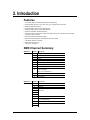
DMX Channel Summary
DMX MODE 1
DMX MODE 2
CHANNEL DESCRIPTION
1
Red
2
Green
3
Blue
4
Yellow
5
Cyan
6
Purple
7
White
8
Strobe
9
Mode Selection
Color-cycle Mode
245 <> 255 : DMX Mode 2
10
ID Address Selection
11
Module Selection
12
Effect Macro
CHANNEL DESCRIPTION
1
Module #1
2
Module #2
3
Module #3
4
5
No Function
6
7
8
Strobe
9
Mode Selection
0 <> 244 : DMX Mode 1
10
ID Address Selection
11
No Function
12
COLORado™ 3 User Manual
6
2007-02-23/16:44
Introduction
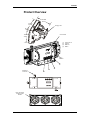
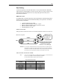
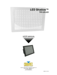
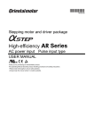
Product Overview
210MM
8.27IN
570MM
22.44IN
Hanging Yoke
190MM
7.48IN
Control Panel
(1)
(2)
(3)
(4)
Power Link out
Power In
DMX Out
DMX In
Power Link Out
180
4
3
2
Interlocking
connectors
1
Each LED surface
is referred to as a
“Module”
COLORado™ 3 User Manual
7
2007-02-23/16:44
3. Setup
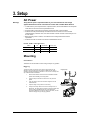
AC Power
Warning!
Verify that the power requirement label on your unit matches the line voltage
applied. All fixtures must be connected to circuits with a suitable Earth Ground.
• To determine the power requirements for a particular fixture, see the label affixed to the back plate
of the fixture or refer to the fixture’s specifications chart.
• A fixture’s listed current rating is its average current draw under normal conditions.
• All fixtures must be powered directly off a switched circuit and cannot be run off a rheostat
(variable resistor) or dimmer circuit, even if the rheostat or dimmer channel is used solely for a 0%
to 100% switch.
• Before applying power to a fixture, check that the source voltage matches the fixture’s
requirement.
• All fixtures must be connected to circuits with a suitable Earth Ground.
P ow e r C a b l e C o n f i g u r a t i o n
CABLE
Pin
International
Screw Color
BROWN
Live
L
Yellow or Brass
BLUE
Neutral
N
Silver
YELLOW/GREEN
Earth
EG (Ground)
Green
Mounting
Orientation
This fixture can be mounted on a truss using a clamp in any position.
Rigging
The fixture includes a mounting yoke to which a rigging clamp can be
attached. You must supply your own clamp and make sure the clamp is
capable of supporting the weight of this fixture. You can order C-clamps from
any CHAUVET dealer or distributor.
1.
Block access below the work area and use suitable and stable
platform when installing or servicing fixture.
2.
Align the clamp screw with the center hole on the yoke and
tighten.
3.
Verify the structure can hold 10 times the weight of all to-be
installed fixtures.
4.
Adjust the angle on the yoke arm as necessary.
5.
Always use a safety cable or chain as a secondary source of
attachment. The safety cable must hold 10 times the weight of the
fixture. If safety cable attachment point is provided that is
permanently affixed to the surface or body of the fixture, use that
instead of looping through a hanging yoke/arm.
COLORado™ 3 User Manual
8
Hanging Clamp
2007-02-23/16:44
Setup
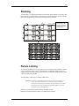
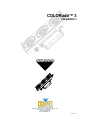
Stacking
The COLORado™ 3 can be stacked vertically and horizontally creating a blinder or a strip light. Stack
them horizontally to increase intensity of the projection for more distant throws or to use as a blinder
effect. The strip light stacking can be used for runway lighting and cycloramas.
Interlocking connectors
provide an easy, fast
and secure method for
stacking units vertically
and horizontally
COLORado™ stacked for use as a Blinder or Large Wash Flood
Fixture Linking
You will need a serial data link to run light shows of one or more fixtures using a DMX-512 controller
or to run synchronized shows on two or more fixtures set to a master/slave operating mode. The
combined number of channels required by all the fixtures on a serial data link determines the number
of fixtures the data link can support.
The COLORado™ 3 fixtures use 12 channels of DMX control.
Important: Fixtures on a serial data link must be daisy chained in one single line. To
comply with the EIA-485 standard no more than 32 devices should be
connected on one data link. Connecting more than 32 fixtures on one serial
data link without the use of a DMX optically isolated splitter may result in
deterioration of the digital DMX signal.
Maximum recommended serial data link distance: 500 meters (1640 ft.)
Maximum recommended number of fixtures on a serial data link: 32 fixtures
COLORado™ 3 User Manual
9
2007-02-23/16:44
Setup
Data Cabling
To link fixtures together you must obtain data cables. You can purchase CHAUVET certified DMX
cables directly from a dealer/distributor or construct your own cable. If you choose to create your own
cable please use data-grade cables that can carry a high quality signal and are less prone to
electromagnetic interference.
DMX Data Cable
Use a Belden© 9841 or equivalent cable which meets the specifications for EIA RS-485 applications.
Standard microphone cables cannot transmit DMX data reliably over long distances. The cable will
have the following characteristics:
•
•
•
•
•
2-conductor twisted pair plus a shield
Maximum capacitance between conductors – 30 pF/ft.
Maximum capacitance between conductor and shield – 55 pF/ft.
Maximum resistance of 20Ω / 1000 ft.
Nominal impedance 100 - 140Ω
Cable Connectors
Cabling must have a male XLR connector on one end and a female XLR connector on the other end.
1
3
2
DMX connector configuration
COMMON
1
3
INPUT
1
3
DMX +
2
2
DMX -
CAUTION
Resistance 120
ohm 1/4w between
pin 2 (DMX -) and
pin 3 (DMX +) of
the last fixture.
OUTPUT
Termination reduces signal errors and
to avoid signal transmission problems
and interference, it is always
advisable to connect a DMX signal
Do not allow contact between the common and the fixture’s chassis ground.
Grounding the common can cause a ground loop and your fixture to perform
erratically. Test cables with OHM meter to verify correct polarity and to make
sure the pins are not grounded or shorted to the shield or each other.
3 - P i n t o 5 - P i n C o n ve r s i o n C h a r t
Note!
If you use a controller with a 5 pin DMX output connector, you will need to use
a 5 pin to 3 pin adapter. CHAUVET Model No: DMX5M.
The chart below details a proper cable conversion:
3 PIN TO 5 PIN CONVERSION CHART
Conductor
3 Pin Female (output)
5 Pin Male (Input)
Ground/Shield
Pin 1
Pin 1
Data ( - )signal
Pin 2
Pin 2
Data ( + ) signal
Pin 3
COLORado™ 3 User Manual
Pin 3
Do not use
Do not use
Do not use
Do not use
10
2007-02-23/16:44
Setup
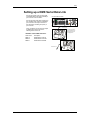
Setting up a DMX Serial Data Link
Connect the (male) 3 pin connector side
of the DMX cable to the output (female) 3
pin connector of the controller.
Universal DMX Controller
Connect the end of the cable coming from
the controller which will have a (female) 3
pin connector to the input connector of
the next fixture consisting of a (male) 3
pin connector.
Then, proceed to connect from the output
as stated above to the input of the
following fixture and so on.
This drawing provides a
general illustration of the
DMX Input/Output panel
of a lighting fixture.
CHAUVET Certified DMX Data Cables
Order Code
Description
DMX1.5
DMX Cable 1.5m/4.9ft
DMX4.5
DMX Cable 4.5m/14.8ft
DMX10
DMX Cable 10m/32.8ft
Continue the link
COLORado™ 3 User Manual
11
2007-02-23/16:44
4. Operating Instructions
Control Options
The COLORado™ 3 is addressable in the DMX range of 001 to 245 in its simplest control form, this
allows for the control of 20 fixtures; however, a secondary “ID” address system exists for use in a
limited DMX universe and architectural environments. The “ID” address system allows the user to
assign up to 66 fixtures within the same DMX address. In effect, multiplying the control of
COLORado’s™ within a single universe to 1,320 fixtures. The COLORado’s™ “ID” address system is
accessed using DMX channel 10. Consideration must be placed when programming live
performances or cues that need to trigger on demand or on a time line. So, to remain within one
second execution time, program no greater than 10 fixtures on ID addressing per DMX channel.
ADAS Overview
Automatic DMX512 Addressing System. Up to 20 fixtures in one universe can be automatically
addressed. In ADAS with ID address setting, upon activation of CH8 and CH10 at value 255, the
fixtures will self DMX address. This address is not random; it is calculated using the {ADAS fader no}
value setting which the user sets in advance. The user can choose between 001 and 244 for the
ADAS fader value, this value would be set to at least the number of control channels for a
COLORado™ (which is 12) or the number of channel faders on a small console maybe 16 OR 18 (i.e.
for a DMX 50). The ADAS DMX address is calculated within each fixture using the following method;
{ADAS fader no value] x (ID – 1)} + 1 = ADAS DMX Address
Let’s see how that translates, I’ll use an ID value of 2 and an {ADAS fader no} value of 12;
{(ADAS=12) x ([ID=2] – 1)} + 1 || {12 x (2-1)} + 1 || {12 x 1} + 1 = (13) DMX Address
COLORado™ Control Quick Setup
For detailed instructions on display panel operations and functions please advance to the section
titled; “Display Panel Functions”. These steps assume that you have read and are familiar with setting
up a DMX serial data link.
DMX-512 control without “ID” address
The COLORado™ operates on 12 channels of DMX. Address each fixture in increments of 12
channels. (I.e. 1,13,25,37 etc…) To save time you can use the same DMX address for each fixture.
All fixtures will then respond simultaneously to control. You may also group your fixtures and address
those groups alike for faster programming and control.
1. Access the control panel’s {DMX512 address} function by pressing the (UP/DOWN)
buttons until the function is displayed
2.
Press the (SET) button to enter panel function.
3.
Use the (UP/DOWN) buttons to increase or decrease channels between 001 and 244.
4.
Press the (SET) button to confirm action.
Deactivate ID addressing in each fixture by setting panel function {ID ON/OFF} to OFF.
{MENU} Â {Settings) Â {ID ON/OFF} Â [OFF]
Notes:
If ID addressing is not deactivated in the fixture’s control panel function,
unintended results may occur if values are present in channel 10. Make sure
values on channel 10 are set to “0”.
COLORado™ 3 User Manual
12
2007-02-23/16:44
Operating Instructions
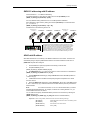
DMX-512 addressing with ID address
Follow instructions 1 ~ 4 for DMX512 addressing.
Activate ID addressing in each fixture by setting panel function {ID ON/OFF} to ON.
{MENU} Â {Settings) Â {ID ON/OFF} Â [ON]
For every DMX512 starting address the user can set 66 separate ID addresses.
Set ID addresses in each fixture by setting panel function {ID address} to incremental values.
(I.e. 1,2,3,4,5,6,etc…)
{MENU} Â {Settings} Â {ID address} Â [01 ~ 66]
ID addresses are accesible using Channel 10.
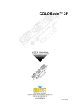
DMX Address: 001
ID Address: 01
DMX Address: 001
ID Address: 02
DMX 512 Controller
DMX Address: 001
ID Address: 03
DMX Address: 013
ID Address: 01
DMX Address: 013
ID Address: 02
DMX Address: 013
ID Address: 03
The figure above shows a simple DMX layout which has used three units at
each DMX address. The three units have different ID addresses which allows
the user to collectively control the whole group of units at that DMX address
by setting Channel 10 to 0, or to control each unit independently by first
selecting the DMX address and then by using Channel 10 to locate the target
ID address. (Note that when using ID addresses it is also possible to activate
ADAS which allows for even more option with DMX addressing and control.
ADAS with ID address
With ADAS activated it is not necessary to set DMX512 addresses on each fixture. The fixture will
automatically assign a temporary DMX address based on the fixture ID address and the value of
{ADAS fader no} that will be assigned.
1.
Set ID addresses as previously explained in ascending numerical order.
2. Set {ADAS ON/OFF} to ON.
{MENU} Â {Settings} Â {ADAS ON/OFF} Â [ON]
3. Set {ADAS fader no} to “12”. Which is the number of control channels on a COLORado™.
{MENU} Â {Settings} Â {ADAS fader no} Â [ 12 ]
4. Activate ADAS DMX addressing by setting Channels 8 and 10 to value 255. (Faders 8 &
10 all the way up!)
5. A DMX address will be calculated and temporarily assigned as explained in the “ADAS
Overview” section.
6. Deactivate ADAS DMX addressing by setting Channels 8, 10 and 11 to value 255. (Faders
8, 10 & 11 and the way up!). All fixtures will return to the DMX address previously set before the
ADAS activation.
Note:
You must set channels 8, 10, and 11 to 255 for EACH fixture you want to
deactivate ADAS DMX addressing. For example, if a fixture has a starting address of 17, you
must set DMX channels 24, 26, and 27.
You can make the temporary ADAS DMX address permanent on each fixture by selecting the
{ADAS copy} function.
{MENU} Â {Settings} Â {ADAS copy} Â [ ON ] (Will store the new DMX address)
Important
COLORado™ 3 User Manual
When using ADAS, all fixtures must have the following settings;
{ID address}
All ID addresses need to be set in ascending order
{ID ON/OFF}
Set to [ ON ]
{ADAS fader no}
All units set to the same value
{ADAS ON/OFF}
Set to [ ON ]
13
2007-02-23/16:44
Operating Instructions
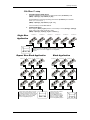
COLORcon™ setup
1.
FIXTURE CONTROL PANEL SETUP
Activate ID addressing in each fixture by setting panel function {ID ON/OFF} to ON.
{MENU} Â {Settings) Â {ID ON/OFF} Â [ON]
Set ID addresses in each fixture by setting panel function {ID address} to incremental
values. (I.e. 1,2,3,4,5,6,etc…)
{MENU} Â {Settings} Â {ID address} Â [01 ~ 66]
It is not necessary to set the DMX address.
2.
CONTROLLER SETUP
When using the {Effect program} function, it is necessary to set the {Settings} Â {Range}
setting, which is the quantity of fixtures in series.
{MENU} Â {Settings} Â {Range} Â [ (No. of fixtures) ]
Single Row
Application
ID Address: 01
ID Address: 02
ID Address: 03
ID Address: 04
ID Address: 05
ID Address: 06
The figure above shows 6 fixtures connected in series with corresponding
addresses. Each fixture has {ID ON} in the fixture’s settings. You must set the
{Range} settings in the controller to [006] before accessing {Effect}
programs.
SET
UP
DOWN
EXIT
Repeat Row Block Application
Block Application
ID Address: 01
ID Address: 02
ID Address: 03
ID Address: 01
ID Address: 02
ID Address: 03
ID Address: 01
ID Address: 02
ID Address: 03
ID Address: 04
ID Address: 05
ID Address: 06
ID Address: 01
ID Address: 02
The figure above shows 9 fixtures connected
in series. Three rows comprised of 3 fixtures
are addressed identically. Each fixture has {ID
ON} in the fixture’s settings. You must set the
{Range} settings in the controller to [003]
before accessing {Effect} programs.
COLORado™ 3 User Manual
ID Address: 07
ID Address: 03
SET
UP
DOWN
ID Address: 08
The figure above shows 9 fixtures
connected in series with
corresponding addresses. Each
fixture has {ID ON} in the fixture’s
settings. You must set the {Range}
settings in the controller to [009]
before accessing {Effect} programs.
EXIT
14
ID Address: 09
SET
UP
DOWN
EXIT
2007-02-23/16:44
Operating Instructions
Setting the DMX address
Each fixture requires a "start address" from 1 to 244. A fixture requiring one or more channels for
control begins to read the data on the channel indicated by the start address. For example, a fixture
that occupies or uses 7 channels of DMX and was addressed to start on DMX channel 100, would
read data from channels: 100, 101, 102, 103, 104, 105 and 106. Choose start addresses so that the
channels used do not overlap and note the start address selected for future reference. The
COLORado™ 3 uses 12 channels of DMX. If this is your first time using DMX, we recommend
reading the DMX Primer in the Appendix Section.
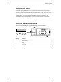
Control Panel Functions
All fixture functions and settings are accessible via the built in control panel interface.
SET
UP
DOWN
EXIT
BUTTON
FUNCTION
SET
Enables the currently displayed menu or sets the currently selected value in to the
selected function
Navigates upwards through the menu list and increases the numeric value when in a
function
Navigates downwards through the menu list and decreases the numeric value when
in a function
Exits from the current menu or function
UP
DOWN
EXIT
COLORado™ 3 User Manual
15
2007-02-23/16:44
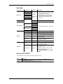
Operating Instructions
Menu Map
MAIN FUNCTION
SUB-FUNCTION
Static color
Red
Green
Blue
Yellow
Cyan
Purple
White
Strobe
000 ~ 255*
(0 ~ 100%)
INSTRUCTION
•
•
User can combine Red, Green and Blue
to generate a custom color
Select intensity over pre-composed
colors yellow, cyan, purple and white
Select strobing frequency between 0
and 20Hz
*Strobe range
is 0 ~ 20
•
•
244 addressable DMX channels
•
Choose from 8 Automatic run programs
ID address
ID ON/OFF
001 ~ 244
1
2
3
4
5
6
7
8
01 ~ 66
On ~ Off
ADAS faders no
01 ~ 244
ADAS ON/OFF
On ~ Off
ADAS copy
On ~ Off
Factory settings
Reset confirm
ON/OFF
On ~ Off
Set Password
[????????]
DMX512 address
Auto program
Settings
SELECTION
Password
Assigns the ID address to a fixture
Either enables or disables ID addressing
Sets the number of ADAS channels for use
when automating DMX channel assignment
Enables the Automatic DMX512
Addressing System
When activated the DMX512 address
assigned by the ADAS will become
permanent on the fixture
Resets fixture to factory default settings
When password is set to on the control
panel will ask for a password each time the
control panel is accessed
Use UP and DOWN buttons to set and
press SET to confirm
Note! If you forget the password use the
following factory password:
UP, DOWN, UP, DOWN, UP, UP, DOWN,
DOWN
Manual Power ON/OFF
The COLORado™ can be turned on and off using the control panel.
POWER
Turn OFF
Turn ON
COLORado™ 3 User Manual
ACTION
When {MENU} is displayed in the LCD panel, hold down the (EXIT) button for 3
seconds to turn off the fixture.
Hold the {EXIT} button for 3 seconds to turn power on.
16
2007-02-23/16:44
Operating Instructions
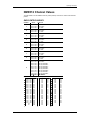
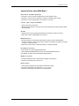
DMX512 Channel Values
The COLORado™ has two DMX512 channel profiles (modes). Channel 9 is used to switch between
profiles.
DMX CONTROL MODE 1
CHANNEL
VALUE
1
000 Ù 004
005 Ù 255
2
000 Ù 004
005 Ù 255
3
000 Ù 004
005 Ù 255
4
000 Ù 004
005 Ù 255
5
000 Ù 004
005 Ù 255
6
000 Ù 004
005 Ù 255
7
000 Ù 004
005 Ù 255
8
000 Ù 004
005 Ù 255
9
000 Ù 004
005 Ù 034
035 Ù 064
065 Ù 094
095 Ù 124
125 Ù 154
155 Ù 184
185 Ù 214
215 Ù 244
245 Ù 255
FUNCTION
Red
No Function
0 Ù 100%
Green
No Function
0 Ù 100%
Blue
No Function
0 Ù 100%
Yellow
No Function
0 Ù 100%
Cyan
No Function
0 Ù 100%
Purple
No Function
0 Ù 100%
White
No Function
0 Ù 100%
Strobe
No Function
0 Ù 20Hz
Mode Selection
No Function
Color-Cycle Mode 1
Color-Cycle Mode 2
Color-Cycle Mode 3
Color-Cycle Mode 4
Color-Cycle Mode 5
Color-Cycle Mode 6
Color-Cycle Mode 7
Color-Cycle Mode 8
DMX MODE 2
Channel 10 (ID address selection)
000 Ù 009
010 Ù 019
020 Ù 029
030 Ù 039
040 Ù 049
050 Ù 059
060 Ù 069
070 Ù 079
080 Ù 089
090 Ù 099
100 Ù 109
110 Ù 119
120 Ù 129
130 Ù 139
140 Ù 149
150 Ù 159
160 Ù 169
170 Ù 179
180 Ù 189
190 Ù 199
200 Ù 209
210
211
COLORado™ 3 User Manual
All IDs
ID 1
ID 2
ID 3
ID 4
ID 5
ID 6
ID 7
ID 8
ID 9
ID 10
ID 11
ID 12
ID 13
ID 14
ID 15
ID 16
ID 17
ID 18
ID 19
ID 20
ID 21
ID 22
212
213
214
215
216
217
218
219
220
221
222
223
224
225
226
227
228
229
230
231
232
233
234
ID 23
ID 24
ID 25
ID 26
ID 27
ID 28
ID 29
ID 30
ID 31
ID 32
ID 33
ID 34
ID 35
ID 36
ID 37
ID 38
ID 39
ID 40
ID 41
ID 42
ID 43
ID 44
ID 45
17
235
236
237
238
239
240
241
242
243
244
245
246
247
248
249
250
251
252
253
254
255
ID 46
ID 47
ID 48
ID 49
ID 50
ID 51
ID 52
ID 53
ID 54
ID 55
ID 56
ID 57
ID 58
ID 59
ID 60
ID 61
ID 62
ID 63
ID 64
ID 65
ID 66
2007-02-23/16:44
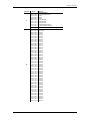
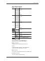
Operating Instructions
CHANNEL
VALUE
11
000 Ù 004
005 Ù 034
035 Ù 064
065 Ù 094
095 Ù 124
125 Ù 154
155 Ù 184
185 Ù 214
215 Ù 255
Module Selection
#1=ON, #2=ON, #3=ON
#1=ON
#2=ON
#3=ON
#1=ON, #2=ON
#2=ON, #3=ON
#1=ON, #3=ON
#1=ON, #2=ON, #3=ON
#1=OFF, #2=OFF, #3=OFF
000 Ù 255
Speed control of Channel 9 Color-Cycle Mode 4
000 Ù 004
005 Ù 008
009 Ù 013
014 Ù 018
019 Ù 023
024 Ù 028
029 Ù 033
034 Ù 038
039 Ù 043
044 Ù 048
049 Ù 053
054 Ù 058
059 Ù 063
064 Ù 068
069 Ù 073
074 Ù 078
079 Ù 083
084 Ù 088
089 Ù 093
094 Ù 098
099 Ù 103
104 Ù 108
109 Ù 113
114 Ù 118
119 Ù 123
124 Ù 128
129 Ù 133
134 Ù 138
139 Ù 143
144 Ù 148
149 Ù 153
154 Ù 158
159 Ù 163
164 Ù 168
169 Ù 173
174 Ù 178
179 Ù 183
184 Ù 188
189 Ù 193
194 Ù 198
199 Ù 203
204 Ù 208
209 Ù 213
214 Ù 218
219 Ù 223
224 Ù 228
229 Ù 233
234 Ù 238
239 Ù 243
244 Ù 248
249 Ù 255
Effect Macro
No Function
Macro 01
Macro 02
Macro 03
Macro 04
Macro 05
Macro 06
Macro 07
Macro 08
Macro 09
Macro 10
Macro 11
Macro 12
Macro 13
Macro 14
Macro 15
Macro 16
Macro 17
Macro 18
Macro 19
Macro 20
Macro 21
Macro 22
Macro 23
Macro 24
Macro 25
Macro 26
Macro 27
Macro 28
Macro 29
Macro 30
Macro 31
Macro 32
Macro 33
Macro 34
Macro 35
Macro 36
Macro 37
Macro 38
Macro 39
Macro 40
Macro 41
Macro 42
Macro 43
Macro 44
Macro 45
Macro 46
Macro 47
Macro 48
Macro 49
Macro 50
12
COLORado™ 3 User Manual
FUNCTION
18
2007-02-23/16:44
Operating Instructions
Important Notes about DMX Mode 1
Red, Green and Blue Selection
• Channels 1, 2 and 3 control overall intensity of each respective color.
• Channels 1, 2 and 3 can be combined to create an unlimited range of colors.
• Channels 1, 2 and 3 have priority over Channels 4, 5, 6 and 7.
Y e l l ow , C y a n , P u r p l e a n d W h i t e
• These colors can not be mixed.
• When levels are raised on more than one of these channels, the lowest channel number
will have priority.
Strobe
• Strobe occurs at every channel with exception to programs on Channel 9 and 12.
• Speed of the strobe is adjustable from 0 to 20 Hz.
Mode Selection
• Channel 9 values 5-244 provides mode selection and can only be activated while
Channels 1 through 7 are at value 0. When channel 9 is between 245 and 255, channels
1 through 7 can be any value.
• When Color-Cycle mode 4 is selected channel 11 controls the speed.
ID address selection
• Use channel 10 to select ID addressed fixtures.
• Each independent DMX address can have up to 66 ID addressed fixtures.
• ID address “0” allows control of all fixtures simultaneously.
Module selection
• Provides individual control of the three LED modules in each fixture.
• Channel 11 has priority over channel 12.
Effect macro
• These are pre-programmed color patterns and module chases.
• Channel 12 has priority over channels (1, 2, 3, 4, 5, 6 & 7).
• Channel 12 has priority over channel 11 if first activated.
COLORado™ 3 User Manual
19
2007-02-23/16:44
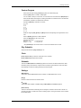
Operating Instructions
DMX CONTROL MODE 2
CHANNEL
VALUE
1
000 Ù 004
005 Ù 034
035 Ù 064
065 Ù 094
095 Ù 124
125 Ù 154
155 Ù 184
185 Ù 255
2
000 Ù 004
005 Ù 034
035 Ù 064
065 Ù 094
095 Ù 124
125 Ù 154
155 Ù 184
185 Ù 255
3
000 Ù 004
005 Ù 034
035 Ù 064
065 Ù 094
095 Ù 124
125 Ù 154
155 Ù 184
185 Ù 255
4
5
6
7
Module 1
No Function
Red
Green
Blue
Yellow
Cyan
Purple
Pink-White
Module 2
No Function
Red
Green
Blue
Yellow
Cyan
Purple
Pink-White
Module 3
No Function
Red
Green
Blue
Yellow
Cyan
Purple
Pink-White
No Function
8
000 Ù 004
005 Ù 255
9
000 Ù 244
245 Ù 255
ID Address
Selection
10
FUNCTION
11
12
Strobe
No Function
0 Ù 20Hz
Mode Selection
DMX MODE 1 (only when channels 1-7 = 0)
DMX MODE 2
See Channel 10 (ID address selection) on
page 16 under DMX Control Mode 1
No Function
Important Notes about DMX Mode 2
Module selection
• Simplified control of modules using channels 1,2 & 3.
Strobe
• Controls the strobe of channels 1, 2 and 3 simultaneously.
• Speed of the strobe is adjustable from 0 to 20 Hz.
Mode selection
• Use channel 9 to switch between DMX mode 1 and DMX mode 2.
ID address selection
• Channel 10 selects ID addressed fixtures.
COLORado™ 3 User Manual
20
2007-02-23/16:44
5. COLORado™ Controller
Overview
LCD Display Panel
MODE
SETUP
UP
DOWN
MODE
Accesses main menu or backs out of sub-menu
SETUP
Selects the currently displayed menu or confirms the current function value
UP
Use to navigate upwards through menu items or increment function values
DOWN
Use to navigate downwards through menu items or decrement function values
Setup
Connect from the OUT on the controller to the DMX Input side of the COLORado™ using a DMX
XLR cable. Visit the section titled: Setting up a DMX Serial Data Link on Page 11.
It is recommended that you power up all COLORado units connected prior to turning on the
controller. This ensures that the controller will auto-detect DMX addresses.
Alternatively you can use {Detect device} from the {Settings} menu.
Set ID addresses on the COLORados in ascending order.
Set the {Range} in the {Settings} menu.
Note
COLORado™ 3 User Manual
There is no need to set ID and Range for {Wash} programs.
21
2007-02-23/16:44
Operating Instructions
Menu Map
MAIN
FUNCTION
SELECTION
SELECTION
SELECTION
Wash
program
Wash [1]
Ù
Wash [8]
Edit
Step time
[001] Ù [255]
Fade time
[001] Ù [255]
Effect
program
Effect [1]
Ù
Effect [8]
Edit
Speed
[001] Ù [100]
Custom
program
Custom [1]
Ù
Custom [8]
Play
schedule
Schedule
Time now
Clock
Edit time
Schedule
Settings
Password
Edit
Scene [1]
Ù
Scene [100]
SELECTION
ID address [000*] Ù [100]
(*0 = all units)
Step time [000] Ù [255]
Fade time [000] Ù [255]
Red [000] Ù [255]
Green [000] Ù [255]
Blue [000] Ù [255]
Module [001] Ù [006]
Strobe [000] Ù [020]
I.e.
12/31/2006
13:50:24
I.e.
12/31/2006
13:50:24
Wash [1]
Ù
Wash [8]
Effect [1]
Start>>>End
Ù
00:00>>00:00
Effect [8]
Custom [1]
Ù
Custom [8]
DMX address [001] Ù [255]
Range
[001] Ù [066]
Allow edit
[YES] Ù [NO]
Detect device
>>>
Reset to
[YES] Ù [NO]
Factory
settings
Password
[ON] Ù [OFF]
ON/OFF
Set password
[
]
Wash Program
Select from the eight existing [Wash] programs and it will instantly play.
Set the [Step time] and the [Fade time] in the [Edit] function if desired.
The unit of time is 5 seconds and it can be adjusted between 1 and 255.
Effect Program
Select from the eight existing [Effect] programs and it will instantly play.
Vary the [Speed] of the effect between 1 and 255.
COLORado™ 3 User Manual
22
2007-02-23/16:44
Operating Instructions
Custom Program
Select from the eight existing [Custom] programs and it will instantly play.
Enter the [Edit] section to create or edit program.
You can create or edit up to 100 scenes. To omit a scene from execution set its [Step time] to 0.
Select the ID address of the target unit. Setting ID address to 0 selects all units in the serial link.
Color/Effects combination for different IDs is allowed.
Specify the [Module] or modules to run active.
0 = 1,2,3
1=1
2=2
3=3
4 = 1,2
5 = 2,3
6 = 1,3
RGB mix using the [Red], [Green] and [Blue] functions and adjusting the range between 0 and
255.
Select a [Strobe] speed from 0-20Hz if desired.
Select the [Step time] for the current scene.
Step time unit values
Range 0 – 10
= 0.1sec per unit
Range 11 – 255
= 1 sec per unit
Set a [Fade time] for the current scene in one second increments from 0 to 255.
Play Schedule
Simply activate this menu [Play schedule] to run.
Clock
[Clock] Â [Time now]: To view the current time on the controller.
[Clock] Â [Edit now]: Edit the time and date.
Schedule
There are 24 Wash, Effect and Custom programs that can be set with Start and End times. Start
times take priority over End times. Programs will not overlap. Programs with the most recent Start
time will always override the existing previously executed program.
Settings
[DMX address]
This function sets the DMX address for the controller. It is addressable from 1 to 250.
[Range]
Enter the number of fixtures connected in series.
[Allow edit]
This function either enables or disables editing in Wash, Effect and Custom programs.
[Detect device]
This is the manual method of detecting and connecting the controller to all new units in series. It is
generally used when you add more units to an existing system. Turning off and then on the controller
has the same effect.
COLORado™ 3 User Manual
23
2007-02-23/16:44
Operating Instructions
[Reset to factory settings]
This function will reset all the settings to the factory defaults except for [Custom] programs.
Factory Default Settings
Setting
Default
[Schedule]
[Wash program]
[Effect program]
[DMX address]
[Range]
[Allow edit]
[Password ON/OFF]
[Set password]
All times in schedule are reset to [00:00]
Step times and fade times are reset to [001]
Speeds are reset to [001]
DMX address is reset to [001]
Range is reset to [066]
Reset to [Yes]
Password is reset to [OFF]
Password is reset to [00000000] Down=0, Up=1
Activating password mode
Set [Password] function to [ON]. This will prompt the user for a password every time the
controller is powered on.
Toggle to [Set password] function in order to change the password.
Input an 8 digit password using the [UP] & [DOWN] keys. Press the [SET] button to confirm.
Note
In the event that the user forgets the password use the following factory
password override:
[UP] Â [DOWN] Â [UP] Â [DOWN] Â [UP] Â [UP] Â [DOWN] Â [DOWN]
Control via external DMX
Programs in the controller can be accessed via an external DMX controller. It will be necessary to
have the DMX address set on the COLORado Controller. The controller operates on 4 channels of
control.
DMX Channel Values
CHANNEL
1
2
COLORado™ 3 User Manual
VALUE
FUNCTION
000 Ù 010
011 Ù 030
031 Ù 040
041 Ù 060
061 Ù 070
071 Ù 090
091 Ù 100
101 Ù 120
121 Ù 130
131 Ù 150
151 Ù 160
161 Ù 180
181 Ù 190
191 Ù 210
211 Ù 220
221 Ù 255
000 Ù 010
011 Ù 030
031 Ù 040
041 Ù 060
061 Ù 070
071 Ù 090
091 Ù 100
101 Ù 120
121 Ù 130
131 Ù 150
151 Ù 160
161 Ù 180
Blackout
Wash [1]
Blackout
Wash [2]
Blackout
Wash [3]
Blackout
Wash [4]
Blackout
Wash [5]
Blackout
Wash [6]
Blackout
Wash [7]
Blackout
Wash [8]
Blackout
Effect [1]
Blackout
Effect [2]
Blackout
Effect [3]
Blackout
Effect [4]
Blackout
Effect [5]
Blackout
Effect [6]
24
2007-02-23/16:44
Operating Instructions
3
4
COLORado™ 3 User Manual
181 Ù 190
191 Ù 210
211 Ù 220
221 Ù 255
000 Ù 010
011 Ù 030
031 Ù 040
041 Ù 060
061 Ù 070
071 Ù 090
091 Ù 100
101 Ù 120
121 Ù 130
131 Ù 150
151 Ù 160
161 Ù 180
181 Ù 190
191 Ù 210
211 Ù 220
221 Ù 255
000 Ù 127
128 Ù 255
Blackout
Effect [7]
Blackout
Effect [8]
Blackout
Custom [1]
Blackout
Custom [2]
Blackout
Custom [3]
Blackout
Custom [4]
Blackout
Custom [5]
Blackout
Custom [6]
Blackout
Custom [7]
Blackout
Custom [8]
OFF
ON
25
2007-02-23/16:44
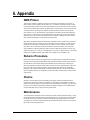
6. Appendix
DMX Primer
There are 512 channels in a DMX-512 connection. Channels may be assigned in any manner. A
fixture capable of receiving DMX-512 will require one or a number of sequential channels. The user
must assign a starting address on the fixture that indicates the first channel reserved in the controller.
There are many different types of DMX controllable fixtures and they all may vary in the total number
of channels required. Choosing a start address should be planned in advance. Channels should
never overlap. If they do, this will result in erratic operation of the fixtures whose starting address is
set incorrectly. You can however, control multiple fixtures of the same type using the same starting
address as long as the intended result is that of unison movement or operation. In other words, the
fixtures will be slaved together and all respond exactly the same.
DMX fixtures are designed to receive data through a serial Daisy Chain. A Daisy Chain connection is
where the DATA OUT of one fixture connects to the DATA IN of the next fixture. The order in which
the fixtures are connected is not important and has no effect on how a controller communicates to
each fixture. Use an order that provides for the easiest and most direct cabling. Connect fixtures
using shielded two conductor twisted pair cable with three pin XLR male to female connectors. The
shield connection is pin 1, while pin 2 is Data Negative (S-) and pin 3 is Data positive (S+). CHAUVET
carries 3-pin XLR DMX compliant cables, DMX-10 (33’), DMX-4.5 (15’) and DMX-1.5 (5’)
Returns Procedure
Returned merchandise must be sent prepaid and in the original packing, call tags will not be issued.
Package must be clearly labeled with a Return Merchandise Authorization Number (RA #). Products
returned without an RA # will be refused. Call CHAUVET and request RA # prior to shipping the
fixture. Be prepared to provide the model number, serial number and a brief description of the cause
for the return. Be sure to properly pack fixture, any shipping damage resulting from inadequate
packaging is the customer’s responsibility. CHAUVET reserves the right to use its own discretion to
repair or replace product(s). As a suggestion, proper UPS packing or double-boxing is always a safe
method to use.
Claims
Damage incurred in shipping is the responsibility of the shipper; therefore the damage must be
reported to the carrier upon receipt of merchandise. It is the customer's responsibility to notify and
submit claims with the shipper in the event that a fixture is damaged due to shipping. Any other claim
for items such as missing component/part, damage not related to shipping, and concealed damage,
must be made within seven (7) days of receiving merchandise.
Maintenance
To maintain optimum performance and minimize wear, fixtures should be cleaned frequently. Usage
and environment are contributing factors in determining frequency. As a general rule, fixtures should
be cleaned at least twice a month. Dust build up reduces light output performance and can cause
overheating. This can lead to reduced lamp life and increased mechanical wear. Be sure to power off
fixture before conducting maintenance.
COLORado™ 3 User Manual
26
2007-02-23/16:44
Appendix
Unplug fixture from power. Clean all glass when the fixture is cold with a mild solution of glass cleaner
or Isopropyl Alcohol and a soft lint free cotton cloth or lens tissue. Apply solution to the cloth or tissue
and drag dirt and grime to the outside of the lens. Gently polish optical surfaces until they are free of
haze and lint.
The cleaning of internal and external optical lenses and/or mirrors must be carried out periodically to
optimize light output. Cleaning frequency depends on the environment in which the fixture operates:
damp, smoky or particularly dirty surrounding can cause greater accumulation of dirt on the unit’s
optics. Clean with soft cloth using normal glass cleaning fluid. - Always dry the parts carefully. - Clean
the external optics at least every 20 days.
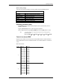
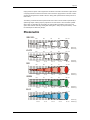
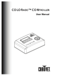
Photometric
RGB100%
WHITE
2
0.9 x 0.5
450
266
216 LUX
4
1.4 x 1.0
6
2.0 x 1.6
788
375
8
2.5 x 2.1
222
10
3.0 x 2.6
Distance (m)
Diameter (m)
177 LUX
15
2370
3
2
1
0
1
2
3
950
15
2970
3
2
1
0
1
2
3
2
0.9 x 0.5
4
1.4 x 1.0
6
2.0 x 1.6
8
2.5 x 2.1
10
3.0 x 2.6
97
78 LUX
8
2.5 x 2.1
10
3.0 x 2.6
Distance (m)
Diameter (m)
RED
360
167
15
1130
3
2
1
0
1
2
3
2
0.9 x 0.5
4
1.4 x 1.0
6
2.0 x 1.6
Distance (m)
Diameter (m)
GREEN
1763
570
270
159
128 LUX
15
3
2
1
0
1
2
3
2
0.9 x 0.5
4
1.4 x 1.0
6
2.0 x 1.6
8
2.5 x 2.1
10
3.0 x 2.6
27
22 LUX
Distance (m)
Diameter (m)
BLUE
COLORado™ 3 User Manual
98
46
15
307
3
2
1
0
1
2
3
2
0.9 x 0.5
4
1.4 x 1.0
6
2.0 x 1.6
27
8
2.5 x 2.1
10
3.0 x 2.6
Distance (m)
Diameter (m)
2007-02-23/16:44
Appendix
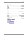
Technical Specifications
WEIGHT & DIMENSIONS
Length........................................................................................................................... 22.5 in (570 mm)
Width .............................................................................................................................. 7.5 in (190 mm)
Height ............................................................................................................................. 8.3 in (210 mm)
Weight ............................................................................................................................... 18 lbs (8.2 kg)
POWER
Operating Voltage ................................................................................................. 90V ~ 240V 50/60 Hz
AC input........................................................................................................................... IEC 60320 C14
Current draw................................................................... (peak <84W @ 120V), (inrush <42W @ 120V)
FUSE
Main............................................................................................................... 20mm Glass 2A Fast Blow
LED
Quantity ....................................................................................... 54 Total, (Red 18, Green 18, Blue 18)
LED................................................................................................................................................ 1 Watt
PHOTO OPTIC
Beam Angle ............................................................................................................................. 18° by 15°
Field Angle............................................................................................................................... 34° by 23°
Illuminance at 1 meter ...................................................................................................675 fc (7,270lux)
CONTROL & PROGRAMMING
Data input ................................................................................................ locking 3-pin XLR male socket
Data output ........................................................................................... locking 3-pin XLR female socket
Data pin configuration ..............................................................................pin 1 shield, pin 2 (-), pin 3 (+)
Protocols........................................................................................................................ DMX-512 USITT
DMX Channels .....................................................................................................................................12
ORDERING INFORMATION
COLORado™ 3 ................................................................................................................. COLORADO3
Technical Support
Address: Service Dept.
3000 N 29th Ct, Hollywood, FL 33020 (U.S.A.)
Support (Email): [email protected]
Telephone: (954) 929-1115 - (Press 4)
Fax: (954) 929-5560 - (Attention: Service)
Website: http://www.chauvetlighting.com
COLORado™ 3 User Manual
28
2007-02-23/16:44