1
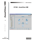
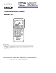
DT301/DT302
1-800-547-5740 • Fax: (503) 643-6322
www.ueitest.com • email: [email protected]
Digital Temperature Logger
INSTRUCTION MANUAL
TABLE OF CONTENTS
Introduction . . . . . . . . . . . . . . . . . . . . . . . . . . . . . . . . . . . . . . . . . .1
Safety . . . . . . . . . . . . . . . . . . . . . . . . . . . . . . . . . . . . . . . . . . . . . .1
Controls and Indicators . . . . . . . . . . . . . . . . . . . . . . . . . . . . . . . .2
Features
LCD Display . . . . . . . . . . . . . . . . . . . . . . . . . . . . . . . . . . . . . . . .3
Buttons . . . . . . . . . . . . . . . . . . . . . . . . . . . . . . . . . . . . . . . . . . .4-5
Setup Instructions
Setup . . . . . . . . . . . . . . . . . . . . . . . . . . . . . . . . . . . . . . . . . . . . . .5
Setting Time/Date . . . . . . . . . . . . . . . . . . . . . . . . . . . . . . . . . . . .6
Changing Thermocouple Type . . . . . . . . . . . . . . . . . . . . . . . . .6
APO . . . . . . . . . . . . . . . . . . . . . . . . . . . . . . . . . . . . . . . . . . . . . .7
Logging interval . . . . . . . . . . . . . . . . . . . . . . . . . . . . . . . . . . . .7-8
Offset . . . . . . . . . . . . . . . . . . . . . . . . . . . . . . . . . . . . . . . . . . . . . .8
Measuring Temperature
Thermocouple . . . . . . . . . . . . . . . . . . . . . . . . . . . . . . . . . . . . . .9
Display . . . . . . . . . . . . . . . . . . . . . . . . . . . . . . . . . . . . . . . . . . . .9
Hold . . . . . . . . . . . . . . . . . . . . . . . . . . . . . . . . . . . . . . . . . . . . . .10
Relative Measurment (DT301) . . . . . . . . . . . . . . . . . . . . . . . . .10
MIN/MAX/AVG . . . . . . . . . . . . . . . . . . . . . . . . . . . . . . . . . . . . .10
Using Offset . . . . . . . . . . . . . . . . . . . . . . . . . . . . . . . . . . . . . . .11
Using Memory
Start/Stop Logging . . . . . . . . . . . . . . . . . . . . . . . . . . . . . . . . .12
Clearin Memory . . . . . . . . . . . . . . . . . . . . . . . . . . . . . . . . . . . .12
View Logged Readings . . . . . . . . . . . . . . . . . . . . . . . . . . . .12-13
Maintenance
Service . . . . . . . . . . . . . . . . . . . . . . . . . . . . . . . . . . . . . . . . .13
Cleaning . . . . . . . . . . . . . . . . . . . . . . . . . . . . . . . . . . . . . . .14
Storage . . . . . . . . . . . . . . . . . . . . . . . . . . . . . . . . . . . . . . . .14
Battery Replacement . . . . . . . . . . . . . . . . . . . . . . . . . . . . .15
Specifications . . . . . . . . . . . . . . . . . . . . . . . . . . . . . . . . . . . .16-17
i
Introduction
The DT301 & DT302
Features include
• IP67 Water/Dustproof rating
• Large Backlit Multi paramater display
• Convenient Probe Storage
• Accepts J,K,T and E type Thermocouples
• Min/Max and Data Hold
• 9,999 Memory position Logging with USB software download
• Relative (DT301)
• Temperature Differential T1-T2 (DT302)
Safety Notes
These are a few common safety practices for those working around
temperature critical environments:
• Follow the manufacturer’s maintenance
procedures when servicing equipment
• Place ONLY thermocouples (type K,J,T or E) in
the DT301 and DT302 thermocouple ports
• Make sure your meter is set for the proper
thermocouple type you are using
• Be sure the thermocouple you use can withstand
the temperature extreme it may be exposed to in your service task
• Properly maintain your thermometer and calibrate
it regularly
1
Controls and Indicators
1
(top view)
4
2
3
1. Thermocouple inputs T1(DT301)T1 and T2 (DT302)
2. Display
3. Buttons
4. USB jack
2
LCD Display Functional Description
2
3
4
5
6
7
8
9
1
10
12
11
1. Primary Display: (DT301: T1 reading)(DT302: T1-T2 reading)
2. TYPE KJET: Type of thermocouple.
3. SETUP: Setup is in progress.
4. RECALL: The logged readings are displayed.
5. OFFSET: The thermocouple measurement includes an offset.
6. HOLD: The display readings do not change.
7. LOW BATTERY: Replace batteries.
8. USB: The thermometer is connected to a PC via USB
interface port.
9. LOG: Readings are being logged.
10. ˚C,˚F, K: Temperature units.
11. Secondary Display: Internal temperature of the thermometer,
MEMORY, MIN, MAX, AVG, and T1 or T2 (DT302)
reading. Shows the memory location initially when a logged
reading is recalled.
12. Time Display: 24-hour clock, shows the INTERVAL length in
SETUP. Shows elapsed time when AVG is on or before clock has
been set. Shows the memory time later on when a logged
reading is recalled.
3
Buttons
NOTE: Press all the dual function buttons momentarily to activate the
Upper Row Function ,and press these buttons for more than 1 second
to activate the Lower Row Functions.
Press this button momentarily to turn the backlight on and
off. The backlight turns off after 30 seconds without any
button pressed. If the battery is low, the backlight is
disabled.
Press this button for more than 1 second to turn the
thermometer on and off.
(DT302) While displaying T1 in the primary display
momentarily pressing this button will scroll through T2 or
the internal temperature of the meter. Press and hold to
change primary display to temperature differential (T1-T2).
While displaying (T1-T2) in the primary display
momentarily pressing this button will scroll through T1, T2,
or the internal temperature of the meter in the lower
display
(DT301) Press this button momentarily to enter or exit the
“RELATIVE” mode.
Press this button momentarily to step through the
maximum, minimum, and average readings in the
secondary display. When viewing logged readings, shows
the maximum, minimum, and average of the logged
readings. Press this button for more than 1 second to turn
off this display.
The “
“ function is activated in the “RECALL” and
“SETUP” mode only.
Press this button momentarily to freeze or release the
displayed readings. Press this button for more than 1
second to switch between Celsius (˚C), Fahrenheit (˚F), and
Kelvin (K).
The “
“ function is activated in the “RECALL” and
“SETUP” mode only.
4
Press this button momentarily to recall or stop viewing
logged readings and MIN/MAX readings. Press this button
for more than 1 second to start or exit “SETUP”.
The “EXIT” function is activated in the “RECALL” and
“SETUP” mode only.
Press this button momentarily to start or stop logging. Press
this button for more than 1 second to clear logged
readings.
To clear logged data press and hold until “
“ appears
in the lower display. To execute the clear press and hold
until “
“ appears.
The “ENTER” function is activated in the “SETUP” mode
only.
Operating Instructions
Before Operating
1. Plug the thermocouple(s) into the input terminal(s).
2. Press “
“ to turn the instrument on. After 1 second, the
thermometer displays the first reading and its internal
temperature. If no thermocouple is plugged into the selected
input or the thermocouple is “OPEN”, the display shows “----”.
1. How to Change Setup Options
Use “SETUP” to reset the thermometer or change the time units, time
settings, thermocouple type, Auto-Power-Off mode, logging interval,
and offset.
Entering and Exiting Setup
When the thermometer is in “SETUP” mode, the display always shows
“SETUP”.
• Press “
“ for more than 1 second to start or exit “SETUP”.
NOTE: The meter must be in normal operation mode.
(Not logging or displaying Min/Max/Avg values)
• Press “
“ momentarily or “
“ for more than 1 second
to exit “SETUP”.
NOTE: Press “
“ or “
“ to scroll to the setup option
you want to change and then press “
“ to accept the
selected setup option.
5
Setting the Date
1. Entering Setup will show the first option of “
2. Press “ENTER” and the display will show “
3. Press “
“ or “
“
“
“ to select the correct year. Press “ENTER”
4. Next the meter will indicate month and day with “
“.
Press “
“ or “
“ to select the correct day. Press “ENTER”
5. Press “
“ or “
“ENTER”
Setting the Time Units
“ to select the correct month. Press
1. While in “SETUP” mode, scroll until the display
shows “
“ in the primary display and “
“ in the
secondary display.
2. Press “
“ to indicate you want to set the time units. The
display shows “h:m” (blinks).
3. Press “
“ or “
“ to select the time units you want to
display, and press “
“ to store the time units in memory.
Setting the Time
1. Press “
“ or “
“ until the display shows “
“.
2. Press “
shows “
“ to indicate you want to set the time. The display
“ (blinks).
3. Press “
“ or “
“ until the display shows the correct hour
(24-hour format), and the press “
“ to store the time in
memory.
NOTE: Holding down “
change more quickly.
“ or “
“ causes the number to
Changing the Thermocouple Type
1. Press “
“ or “
“ until the display shows “
“.
2. Press “
“ to display the thermocouple type choices (KJET).
The currently selected thermocouple type blinks.
3. Press “
“ or “
“ until the thermocouple type you want
appears on the display, and then press “
“ to store the
thermocouple type in memory.
6
Changing the Auto-Power-Off Time (in minutes)
The thermometer enters Auto-Power-Off mode if no button is pressed
for 30 minutes. Press “
“ to turn the thermometer on. You can
enable or disable Auto-Power-Off mode and also you can select the
Auto-Power-Off mode and also you can select the Auto-Power-Off time
(in minutes) among the 9 choices below:
1 00:10 h:m
4 00:40 h:m
7 00:70 h:m
1. Press “
“ or “
2 00:20 h:m
5 00:50 h:m
8 00:80 h:m
3 00:30 h:m (default)
6 00:60 h:m
9 00:90 h:m
“ until the display shows “
“.
2. Press “
“ to display “ “ or “ “ in the time display. If
“ “ is displayed, press “
“ or “
“ to select “ “.
3. Press “
“ to display the choice number 3 in the secondary
display and 00:30 h:m in the time display.
4. Press “
“ or “
“ until the display shows the Auto-PowerOff Time choice number you want, and then press “
“ to
store the Auto-Power-Off setting in memory.
Auto-Power-Off mode is automatically disabled in MIN/MAX
and logging modes.
Changing the Logging Interval
The logging interval determines how often the thermometer stores
logged readings in memory. You choose the length of the logging
interval.
The thermometer stores logged readings at the end of each logging
interval.
You can select a logging interval of 1 second (1), 10 seconds (2), 1
minute (2), 10 minutes (4), or user-defined (
).
1. Press “
“ LOG “.
“ or “
“ until the display shows “
2. Press “
“ to display the logging interval choices.
“ and
3. Press “
“ or “
“ until the display shows the logging
interval you want, and then press “
“ to select.
7
4. If you selected a user-defined logging interval (1 second to
23 hours and 59 minutes).
• Press “
“ or “
“ until the display shows “h:m” or
“m:s”, and then press “
“ to select. The last number in the
time display blinks.
• Press “
“ or “
“ until the logging interval you want
appears on the display, and then press “
“ to select.
Holding down “
more quickly.
“ or “
“ causes the number to change
Changing the Offset
You can adjust the thermometer’s readings to compensate for the
errors of a specific thermocouple. The allowable compensation range is
±5.0˚C or K, and ±9.0˚F. (DT302 you can store individual offsets for T1
and T2)..
1. Press “
“ or “
“ until the display shows “ OFFSET ”.
2. Press “
“ to display T1 reading (blinks), T1 offset.
3. (DT302)
Press “
“ to display T1 reading (blinks), T1 offset.
Press“
“ or “
“ to display T1 or T2 in the
primary display to select 1 input.
(DT301)
Press “
“ to display reading and offset.
The temperature measurement plus the offset
appears in the primary display. The offset appears in
the secondary display.
3. Press “
“ or “
“ until the primary display shows the
correct reading, and then press “
“ to store the offset setting
in memory.
Remember to reset the offset to 0.0 when it is no longer needed.
NOTE: If T1 or T2 has no offset at all, the display does not
show “ OFFSET ”.
8
Resetting the Thermometer
If you want to retore the thermometer settings as delivered from the
factory, press “
“ or “
“ until the display shows “
“ then
press “
“ to display “
“ in the primary display. Press “
“ to
exit setup.
2. How to Measure Temperature
Connecting a Thermocouple
Thermocouples are color coded by based on the ANSI color code:
Type
J
K
Color
Black
Yellow
Type
T
E
Color
Blue
Purple
1. Plug a thermocouple into the input terminal(s).
2. Set the thermometer for the correct thermocouple type. To
change the thermocouple type, see “How to Change
Setup Options”.
Displaying Temperature
1. Press “
“ for more than 1 second to select the correct
temperature unit.
2. Hold or attach the thermocouple(s) to the measurement location.
The temperature reading appears in the selected display.
3. (DT302)
Press “
“ momentarily to show T1 reading in the
primary display, and toggle showing T2 reading, or
the internal temperature of the thermometer in the
secondary display.
Press “
“ for more than 1 second to show T1-T2
reading in the primary display.
Press “
“ momentarily to toggle showing T1, T2,
or the internal temperature of the thermometer in the
secondary display while the primary display shows
the T1-T2 reading.
NOTE: The display shows “----” when a thermocouple is not
connected. The display shows “
“ (OVERLOAD) when the
temperature being measured is outside the thermocouple’s
valid range.
9
Holding the Displayed Temperature
1. Press “
“ momentarily to freeze the readings on the display.
The display shows “ HOLD “.
2. Press “
“ momentarily again to turn off the “ HOLD “ function.
NOTE: Press “
“ when turning on the thermometer to test the
display. All display segments appear.
Using the Relative Measurements (DT301)
1. Press “
“ momentarily to enter or exit the “RELATIVE”
mode. When the thermometer is in Relative mode, the display
shows “REL”.
2. The difference value between the stored reference value and the
measured reading value appears in the secondary display.
Viewing the MIN/MAX/AVG Readings
NOTE: MIN/MAX and AVG values are captured only while this
mode is active. Exiting the MIN/MAX/AVG mode will clear all
values.
1. Press “
“ momentarily to step through the MIN (minimum),
MAX (maximum), or the AVG (average) readings in the
secondary display.
The elapsed time since entering MIN/MAX mode appears with
the average reading, or the time at which the MINIMUM or
MAXIMUM occurred appears with the MINIMUM or
MAXIMUM reading on the display.
3. (DT302)
Press “
“ momentarily to toggle showing the
maximum (MAX) of T1, or T2 readings and its
displayed time.
Press “
“ for more than 1 second to show the
maximum (MAX) of T1-T2 reading and its
displayed time.
The minimum (MIN) or average (AVG) reading can be
displayed in the similar way.
3. Press “
“ for more than 1 second or “
than 1 second to exit MIN/MAX mode.
10
“ button for more
Using the Offset to Compensate for Probe Errors
Use the offset option in “SETUP” to adjust temperature readings to
compensate for the errors of a specified thermocouple.
1. Plug the thermocouple into the input terminal.
2. Place the thermocouple in a known stable temperature
environment (such as an ice bath or a dry well calibrator).
3. Allow the readings to stabilize.
4. In “SETUP”, change the offset until the primary display reading
matches the calibration temperature. See “How to Change
Setup Options”
3. How to Use Memory
During logging session, the thermometer stores logged readings in its
memory. At the end of the logging session you can view the logged
readings on the display. You can also transfer the logged readings to a
PC running the provided WS600 software (optional), see “How to
Communicate with a PC”.
WS600 displays the readings on an online form, which you can print or
store for later use.
Initial Conditions and Data Entries
Logged readings include initial conditions and data entries. The initial
conditions are the thermocouple type and the offsets for each
thermocouple input. You can only view initial conditions using WS600.
The data entries are a time stamp and the T1, T2 or T1-T2 reading for
the DT302 and current reading for the DT301. You can view these values
by pressing “
“ momentarily or using WS600. The thermometer has
9,999 memory locations. The thermometer stores 9,999 sets of
temperature readings and one set of initial conditions when logging
continuously. It stores 9,999 sets of temperature readings and initial
conditions when logging individual points manually.
11
Starting and Stopping Logging
Memory clear, and PC communications are in accessible during logging.
Recall function is enabled during logging.
1. Set the time and the logging interval, see “How to Change
Setup Options”.
2. Press “
“ momentarily to start logging. The display
shows “ LOG “.
3. Press “
“ momentarily again to stop logging.
Clearing Memory
When memory is full, “
“ appears in the secondary display and
logging stops. You can clear memory in normal or MIN/MAX mode.
1. Press “
“ for more than 1 second to display “
“RECALL” mode.
“ in the
2. Press “
“ for more than 1 second again to delete all logged
readings from memory.
3. Press “
“ momentarily or turn off the thermometer to stop
clearing memory.
Viewing Logged Readings
1. Press “
“ momentarily to display the last logged reading. If
there is no logged readings, “
“ appears in the secondary
display, and the thermometer returns to the previous mode.
2. Press “
“ to scroll through the logged readings. The display
shows each logged reading and its time stamp, which is
displayed 2 seconds after its memory location appeared in the
secondary display.
3. Press “
“ momentarily to step through the minimum,
maximum, average, and currently logged reading.
4. (DT302) Press “
“ momentarily to display the logged readings
you want to view. Press “
“ for more than 1 second to display
differential values between the logged readings you want to view.
12
5. Press “
“ momentarily or turn off the thermometer to stop
viewing logged readings.
NOTE: The thermometer calculates the minimum and maximum
of all logging sessions in memory.
4. How to Communicate with a PC
The thermometer is equipped with an USB interface port. A Windows®
software (WS600) CD and USB interface cable kit is available for data
acquisition applications. This kit is required to connect the thermometer
to a PC. The thermometer comes with this optional accessory kit.
You can transfer the currently measuring data and the contents of the
thermometer’s memory to a PC using this kit. Refer to the “HELP”
menu in the WS600 for further details.
When the meter starts to send logged readings to a PC while the
logging function is activating, the logging function is disabled.
NOTE: Logging is disabled while communicating with a PC.
Maintenance
Periodic service
WARNING!
Repair and service of this instrument is to be performed by qualified
personnel only. Improper repair or service could result in physical
degradation of the meter. This could alter the protection from
electrical shock and personal injury this meter provides to the
operator. Perform only those maintenance tasks that you are
qualified to do.
13
These guidelines will help you attain long and reliable service from
your meter:
1. Calibrate your meter annually to ensure it meets original
performance specifications.
2. Keep your meter dry. If it gets wet, wipe it dry immediately. Liquids
damage electronic circuits.
3. Whenever practical, keep the meter away from dust and dirt, which
can cause premature wear.
4. Although your meter is built to withstand the rigors of daily use, it
can be damaged by severe impacts. Use reasonable caution when
using and storing the meter.
Cleaning and Decontamination
Periodically clean your meter’s case using a damp cloth. DO NOT use
abrasives, cleaning solvents or strong detergents, as they may damage
the finish or affect the reliability of the structural components.
Storing the Thermocouples
The thermocouples with wire spools can be stored in the back of the
thermometer.
1. Wind the wire around the wire spool.
2. Thread the end of wire through
a hole of the wire spool.
3. Thread the end of wire through
the other hole of the wire spool.
4. Insert the end of wire under the
loop and pull the end of wire.
14
Battery Replacement
Always use a fresh replacement battery of the specified size and type.
Immediately remove the old or weak battery from the meter and
dispose of it in accordance with your local disposal regulations. Old or
defective batteries can leak chemicals that corrode electronic circuits.
WARNING!
To avoid electric shock, be sure to turn off the meter’s power and
disconnect thermocouples from any equipment before you remove
or install batteries.
To install a new battery, follow these procedures:
1. Remove the screws from the battery compartment cover on the
back of the meter and lift the cover (Fig 1).
2. Remove and discard the old batteries. Always dispose of old
batteries promptly in a manner consistent with local disposal
regulations.
WARNING!
Under NO circumstance should you expose batteries to extreme heat
or fire as they may explode and cause injury.
3. Place a fresh batteries in the compartment.
NOTE: If you do not plan to use the meter for a month or more,
remove the battery and store it in an area that won’t be damaged by a
leaking battery.
4. Reattach the battery compartment cover to the meter and
reinstall the screws.
15
Specifications
Environmental
Operating Temperature
Storage Temperature
Humidity
Altitude
14˚ to 122˚F (-10˚ to 50˚C)
-40˚ to 140˚F (-40˚ to 60˚C)
Non condensing <50˚F (10˚C)
85% RH: 50˚ to 86˚F (10˚ to 30˚C)
70% RH: 86˚ to 104˚F (30˚ to 40˚C)
45% RH: 104˚ to 122˚F (40˚ to 50˚C)
Operating - up to 200 m
Storage - 10000 m
General
Dimension
18.3 (H) x 9.4 (W) x 4.3 (D) cm
(7.20” x 3.70” x 1.70)
Approx. 460 g (16.2 oz)
2 x LR03 (AAA) type 1.5V
Weight
Battery
Certification
Safety
CE
IEC 1010-1 (2001), UL 3111-1 (6, 1994),
EN 61010-1 (2001), CSA C22.2
No. 1010.1 (1992)
CAT I
OVERVOLTAGE (Installation) CATEGORY I,
Immersion (30 min)
Pollution Degree 2 per IEC 1010-1
IP67 according to IEC 60529
& Dust proof
Thermocouple
Instrument Part #
DT301
ATT19
Type
J-Type
DT302
K-Type
ATT39
Specifications
(-40˚- 950˚F/-40˚-510˚C) 48”
w/oven clip
(-40˚- 950˚F/-40˚-510˚C) 48”
Teflon coated
Wire wrap handle
16
Electrical
Measurement range
Display Resolution
Measurement
Accuracy
Temperature
Coefficient
Real Time
Clock Tolerance
Maximum Differential
Common Mode
Voltage
Temperature Scale
J-Type: -346˚ to +2192˚F (-210˚ to +1200˚C)
K-Type: -328˚ to +2498˚F (-200˚ to +1370˚C)
T-Type: -418˚ to +752˚F (-250˚ to +400˚C)
E-Type: -238˚ to +1832˚F (-150˚ to +1000˚C)
0.1˚F/˚C < 1000˚
1.0˚F/˚C ≥ 1000˚
J, K, T, and E-Type; ±[0.1% +1.0˚F (0.5˚C)]
[Below -148˚F (-100˚C): add 0.2% of reading
for J, K, and E-Type; and 0.1% of reading for
T-Type]
0.01% of reading 0.1˚F per ˚F(+0.05˚C per ˚C)
for <+64˚F (+18˚C) or +82˚F (+28˚C)
[Below -148˚F (-100˚C): add 0.05% of reading
for J, K, and E-type; and 0.1% of reading for
T-type]
About 1 second per day
1V (maximum voltage difference between
any pair of inputs)
ITS-90 (International Temperature Scale
of 1990)
Applicable Standards N.I.S.T. Monograph 175 revised to ITS-90
Accuracy is specified for ambient temperatures between 64˚F (18˚C)
and 82˚F (28˚C) for a period of 1 year. The above specifications do not
include thermocouple error.
17
®
DT301/DT302
Digital Temperature Logger
Limited Warranty
The DT301 and DT302 are warranted to be free from defects in
materials and workmanship for a period of five years from the
date of purchase. If within the warranty period your instrument
should become inoperative from such defects, the unit will be
repaired or replaced at UEi’s option. This warranty covers normal
use and does not cover damage which occurs in shipment or
failure which results from alteration, tampering, accident, misuse,
abuse, neglect or improper maintenance. Batteries and
consequential damage resulting from failed batteries are not
covered by warranty.
Any implied warranties, including but not limited to implied
warranties of merchantability and fitness for a particular
purpose, are limited to the express warranty. UEi shall not be
liable for loss of use of the instrument or other incidental or
consequential damages, expenses, or economic loss, or for any
claim or claims for such damage, expenses or economic loss.
A purchase receipt or other proof of original purchase
date will be required before warranty repairs will be rendered.
Instruments out of warranty will be repaired (when repairable) for
a service charge. Return the unit postage paid and insured to:
1-800-547-5740 • FAX: (503) 643-6322
www.ueitest.com • Email: [email protected]
This warranty gives you specific legal rights. You may also have
other rights which vary from state to state.
PLEASE
RECYCLE
Copyright © 2008 UEi
DT304-MAN 1/08