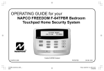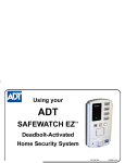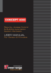
1
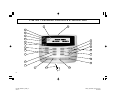
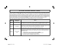
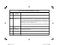
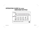
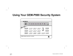
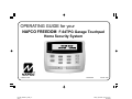
OPERATING GUIDE for your NAPCO FREEDOM F-64TPG Garage Touchpad Home Security System SYSTEM READY 10/15/06 12:05PM R Freedom F-64TPG Touchpad © NAPCO 2006 PATENTED OI320A 9/06 1 F-64TPG_OI320A.03_USER_2... page 1 Friday, September 15, 2006 11:40 Composite INTRODUCTION Congratulations on your purchase of a new Freedom Garage Door Security System. This revolutionary new concept in residential security makes using your system easier than ever before possible, because the system uses its computerized control panel to continually monitor the status of your garage door. It actually anticipates what command it should expect from you next--simply requiring just one button to press to effortlessly operate your security system, whether you’re going, returning or staying in for the night. Now everyone in your family, young and old alike, will enjoy the true peace-of-mind you would expect from a quality, state-ofthe-art NAPCO Security System, without the fuss of remembering confusing numerical codes to operate it. Simplicity and convenience begin with your System’s one-touch STAY or AWAY buttons, then just open or close the garage door as usual! Day in and day out, that’s all there is to it. This booklet contains important information about the operation of your NAPCO Freedom Security System. Please read it through and retain it for handy reference. Because your system is customized for your home and lifestyle, you may find subjects mentioned here, that do not apply to your system. Rest assured your security system has been configured by your Security Professional to best suit you and the system itself has been meticulously designed and engineered to the highest industry standards. Please test your system at least once a week as described below. IMPORTANT - TEST YOUR SYSTEM WEEKLY From a Ready Condition (Disarmed State) 1 Test your sounding device and backup battery (Perform these tests only on weekends or at a time designated by your alarm company) 1. While disarmed, press MENU. 2. Press MENU until ACTIVATE SIREN TEST appears in the display. 3. Press YES to execute the test. The alarm will sound for about two seconds. • If the alarm does not sound, call for service. • If the battery is low, LOW BATTERY E02-00 SERVICE will appear in the display indicating a low battery condition. Allow 24 hours for the battery to recharge. If the trouble continues, call for service. 2 Test your central station communicator (Activate Dialer Test programmed? YES NO) 1. 2. 3. 4. Notify your Central Station of the impending test. While disarmed, insert your I-FOB into the Touchpad. Press MENU. Press MENU until ACTIVATE DIALER TEST appears in the display. Press YES to send a test code to the central station. • If the test is not successful, COMM FAIL E03-00 SERVICE will display, indicating a communication failure. Call for service. Note: Any subsequent successful transmission will clear a Failure to Communicate system trouble. 2 F-64TPG_OI320A.03_USER_2... page 2 Friday, September 15, 2006 11:40 Composite T AB L E O F C O N T E N T S TABLE OF CONTENTS INTRODUCTION................................................................................ 2 TESTING THE SYSTEM.................................................................... 2 GARAGE TOUCHPAD INDICATORS AND CONTROLS .................. 4 ARMING WHEN LEAVING ................................................................ 6 BYPASSING FAULTED ZONES ....................................................... 7 ARMING STAY: PROTECTING YOURSELF AT HOME................... 8 ARMING AND LEAVING WITH OTHERS STAYING ......................... 9 EXITING WITH THE SYSTEM ALREADY ARMED ........................ 10 EMERGENCY BUTTONS ................................................................ 12 DISARMING THE SYSTEM ............................................................. 13 SILENCING AN ALARM................................................................... 14 FIRE PROTECTION......................................................................... 15 TOUCHPAD MENU MODE.............................................................. 17 USER PROGRAM MODE ................................................................ 21 SYSTEM TROUBLE ERROR CODES ............................................. 24 USER I-FOB LIST ............................................................................ 29 LOST GARAGE DOOR OPENER MODE ........................................ 30 FCC PART 68 STATEMENT ........................................................... 31 LIMITATIONS OF THIS ALARM SYSTEM....................................... 32 LIMITED WARRANTY...................................................................... 34 FCC PART 15 STATEMENT............................................................ 36 R IF THE ALARM IS SOUNDING: To silence an alarm, insert your I-FOB key into the slot on the Touchpad and remove when alarm has silenced. Proceed with caution! (See pages 13 & 14). ALARM TIME OUT: _________ Minutes FOR SERVICE, CALL: _____________________ TO CANCEL AN ALARM REPORT, CALL: ____________________ 3 F-64TPG_OI320A.03_USER_2... page 3 Friday, September 15, 2006 11:40 Composite F - 6 4 T P G T O U C H P AD C O N T R O L S & I N D I C AT O R S 1 18 19 20 21 BYPASS FIRE FIRE TBL SYS TBL 22 2 SYSTEM READY 10/15/06 12:05PM 14 15 3 16 5 6 10 7 11 12 8 4 9 4 17 13 4 F-64TPG_OI320A.03_USER_2... page 4 Friday, September 15, 2006 11:40 Composite F - 6 4 T P G T O U C H P AD C O N T R O L S & I N D I C AT O R S 1 2 3 4 5 6 LCD Window – 32 character LCD displays system status messages, zone descriptions, system troubles, etc. STATUS Light. Lights (green) to indicate that the system is ready for arming. If a zone is not secured, the light will be off and the zone will display in the window. If a zone has been bypassed, the STATUS light will blink while armed. ARMED Light. Lights (red) to indicate that the system is armed. If an alarm has occurred, the ARMED LED will be flashing. Alarm Speaker – Will sound a LOUD steady sweep tone when intrusion is detected or a distinct pulsating tone for a fire alarm condition. Also chirps to indicate armed AWAY, and provides for audible voice prompts. STAY Button – Press once to initiate the arm Stay sequence. Stay Mode bypasses all interior zones simultaneously to allow free movement within the premises. Hold down for 2 seconds if all zones secure to eliminate 60-second pre-arm delay. AWAY Button – Press to initiate arm AWAY sequence when no one is to remain home. Exit and close garage door from outside the premises. System will be fully armed with all perimeter and F-64TPG_OI320A.03_USER_2... page 5 interior devices activated. 7 BYPASS Button – Press to enter the Bypass Menu, where system functions are displayed in the LCD window. Press YES to select the desired function; press RESET to exit. Bypassing a zone deactivates the zone from the system. 8 MENU Button – Press to enter Function Mode, in which available system functions are displayed in the LCD window. The desired function is then selected by pressing the YES button. Press RESET to exit. 9 RESET Button – Press to silence Fire alarms, troubles and exits Function Mode (see MENU Button). 10 YES Button – Press to select the desired function in menus (see MENU Button, above). 11 NO Button – Press to answer no to menu questions and proceed to the next question (see MENU Button, above). 12 ENTER Button – Press to accept displayed value and to move cursor to next position. 13 Integral PIR – Used to detect intruders and your presence near the Touchpad during arming and disarming. Do not block. 14 FIRE Button – Press and hold down for 2 seconds to alert the Central Station of a fire emergency. 15 16 17 18 19 20 21 22 + AUX Button – Press and hold down for 2 seconds to alert the Central Station of a auxiliary emergency. Police Button – Press and hold down for 2 seconds to alert the Central Station of a police emergency. I-FOB – The I-FOB is a uniquely coded digital key. Insert the I-FOB into its keyhole to disarm the system and silence the siren in case of an alarm. Slide Plate – Lift to view brief descriptions of Touchpad buttons and procedures. Bypass Icon – Appears as a reminder that zones have been bypassed (by pressing the BYPASS button). If it is necessary to bypass any inoperative zones, it is important to have the zones repaired as soon as possible. Fire Icon – Steady indicates a fire alarm condition. Flashing indicates fire alarm sounding. Fire TBL Icon – Indicates a problem on a fire zone is detected. System TBL Icon – Indicates a trouble condition exists on the system. Press SILENCE to silence sounder and display the trouble. 5 Friday, September 15, 2006 11:40 Composite A R M I N G W H E N L E AV I N G If you are leaving with no other family members remaining home: 1 2 SYSTEM READY Check the Touchpad indicators. The green STATUS light must be ON-STEADY, and the LCD display will read "SYSTEM READY", indicating that the system is ready to arm. • If the green STATUS light is off and zones are scrolling in the display, a perimeter zone is faulted or a monitored deadbolt (other than your exit door) is unlocked. Check the open zones listed and close the door, window, or lock the deadbolts as needed. If you cannot immediately secure the zones or lock the deadbolts, they may be bypassed (see page 7). Press the AWAY button. AWAY The Touchpad will voice prompt the correct action. "To arm Away, exit and close garage door." • If you change your mind after pressing AWAY, press RESET to clear arming. 3 4 Open the garage door and exit within 3 minutes. (Note: If your garage door motor fails, see page 13). When the garage door closes, the Touchpad will sound one chirp indicating the system is armed. If the garage door has not been closed within the pre-exit delay time, the system will revert back to a disarmed state. If the system detects movement inside the premises during the exit delay time, it will automatically revert to Stay mode, providing perimeter protection with the interior protection (motion sensors) turned off. (See ARMING STAY: PROTECTING YOURSELF AT HOME- page 8). 6 F-64TPG_OI320A.03_USER_2... page 6 Friday, September 15, 2006 11:40 Composite B Y P AS S I N G F A U L T E D Z O N E S If you are trying to arm with a faulted zone or zones, the LCD display will clearly indicate which zone(s) are faulted. If you cannot repair the zone(s), they may be temporarily removed from the system, or bypassed, using the following procedure: 1 2 3 Press the BYPASS button. BYPASS YES× NOØ BYPASS 4 "Press down arrow to scroll through zone list and press BYPASS to select zone to bypass" The LCD window will list all zones in your system. Scroll forward or backward through the zone list using the YES × and NO Ø buttons. As you scroll through your zones, the Bypass or Trouble icons will appear (or not appear) depending on the status of each zone. As you scroll through the zone list using the YES × and NO Ø buttons, when the zone that you wish to bypass appears on the Touchpad LCD screen, press BYPASS. The Bypass icon will appear on the LCD screen. Press either the STAY or AWAY button. If arming AWAY, open the garage door and exit. (Note: See page 13 if your garage door motor fails). "Please exit and lock door to arm system" The system will arm with the faulted zones bypassed. When the garage door closes, the Garage Touchpad will give one chirp to indicate the system has armed. Warning: Bypassed zones are unprotected. If a faulted zone cannot be secured, have the system checked as soon as possible. 7 F-64TPG_OI320A.03_USER_2... page 7 Friday, September 15, 2006 11:40 Composite A R M I N G S T A Y : P R O T E C T I N G Y O U R S E L F AT H O M E Arming in the Stay mode allows you to remain home with the perimeter protection active but with the interior protection off, so that you may move freely within the premises. Arm Stay at the Garage Touchpad as follows: 1 2 Check the Touchpad indicators. The green STATUS light must be ON-STEADY, and the LCD disSYSTEM READY play will read "SYSTEM READY", indicating that the system is ready to arm. • If the green STATUS light is off and zones are scrolling in the display, a perimeter zone is faulted or a monitored deadbolt (other than your exit door) is unlocked. Check the open zones listed and close the door, window, or lock the deadbolts as needed. If you cannot immediately secure the zones or lock the deadbolts, they may be bypassed (see page 7). Press the STAY button. STAY The Touchpad will voice prompt the correct action. "The system is arming in Stay mode" • If you change your mind after pressing AWAY, press RESET to clear arming. 3 ARMED 4 If the garage door is already closed, the ARMED indicator will light and the LCD display will read "ARMING STAY". The system will arm in the Stay mode within 3 minutes. If the garage door is NOT closed, close the garage door from the inside to arm the system. If the garage door has not been closed within the exit delay time period (usually within 3 minutes of pressing STAY, but this time period can be changed by your installer), the system will revert back to a disarmed state. (Note: See page 13 if your garage door motor fails). 8 F-64TPG_OI320A.03_USER_2... page 8 Friday, September 15, 2006 11:40 Composite A R M I N G AN D L E AV I N G W I T H O T H E R S S T A Y I N G If you are arming and leaving with other family members remaining home: 1 2 SYSTEM READY Check the Touchpad indicators. The green STATUS light must be ON-STEADY, and the LCD display will read "SYSTEM READY", indicating that the system is ready to arm. • If the green STATUS light is off and zones are scrolling in the display, a perimeter zone is faulted or a monitored deadbolt (other than your exit door) is unlocked. Check the open zones listed and close the door, window, or lock the deadbolts as needed. If you cannot immediately secure the zones or lock the deadbolts, they may be bypassed (see page 7). Press the STAY button. STAY The Touchpad will voice prompt the correct action. "The system is arming in Stay mode" • If you change your mind after pressing AWAY, press RESET to clear arming. The red ARMED light will turn on steady, indicating the 3 minute exit delay period. ARMED 3 4 Open the garage door and exit. (Note: See page 13 if your garage door motor fails). Close the garage door from the outside to arm the system (with your existing garage door opener remote control). If the garage door has not been closed within the exit delay time period (usually within 3 minutes of pressing STAY, but this time period can be changed by your installer), the system will revert back to a disarmed state. 9 F-64TPG_OI320A.03_USER_2... page 9 Friday, September 15, 2006 11:40 Composite E X I T I N G W I T H T H E S Y S T E M AL R E A D Y A R M E D If the system is Armed STAY and you are leaving with other family members remaining home: 1 Press the STAY button. STAY ARMED The Touchpad will voice prompt the correct action. "The system is arming in Stay mode" The red ARMED light will turn on steady, indicating that you have up to 3 minutes to exit through the garage and close the door. 2 Open the garage door from the inside. System will disarm. 3 Exit the garage. 4 Close the garage door from the outside to arm the system (with your existing garage door opener remote control). If the garage door has not been closed (usually within 3 minutes of arming, but this time period can be changed by your installer), the system will revert back to a disarmed state. (Note: See page 13 if your garage door motor fails). 10 F-64TPG_OI320A.03_USER_2... page 10 Friday, September 15, 2006 11:40 Composite E X I T I N G W I T H T H E S Y S T E M AL R E A D Y A R M E D If the system is Armed STAY and you are leaving with NO other family members remaining home: 1 Press the AWAY button. AWAY The Touchpad will voice prompt the correct action. • If you change your mind after pressing AWAY, press SILENCE to clear arming. ARMED The red ARMED light will turn on steady, indicating that you have up to 3 minutes to exit through the garage and close the door. 2 Open the garage door from the inside. System will disarm. 3 4 Exit the garage. Close the garage door from the outside (with your existing garage door opener remote control) to arm the system. The Garage Touchpad will give one chirp to indicate the system has armed. If the garage door has not been closed within the exit delay time period, the system will revert back to a disarmed state. If the system detects movement inside the premises (usually within 3 minutes of arming, but this time period can be changed by your installer), it will automatically revert to Armed STAY mode, providing perimeter protection with the interior protection (motion sensors) turned off. (See ARMING STAY: PROTECTING YOURSELF AT HOME- page 8). (Note: See page 13 if your garage door motor fails). 11 F-64TPG_OI320A.03_USER_2... page 11 Friday, September 15, 2006 11:40 Composite EMERGENCY BUTTONS Emergency Buttons (Only available if programmed). The Emergency Buttons, if programmed, are always active, whether the system is armed or disarmed. The Emergency Button must be Held Down for 2 seconds to activate the emergency alarm and transmit the signals to central station. Fire Emergency Hold down the Fire button to alert the central station of a fire emergency. * (Fire Emergency programmed? YES NO) Auxiliary Emergency Hold down this button to alert the central station of an auxiliary emergency. * (Auxiliary Emergency programmed? YES NO) Auxiliary Emergency: _______________________________________ Police Emergency Hold down the Police Emergency button to alert the central station of a police emergency. * (Police Emergency programmed? YES NO) 12 F-64TPG_OI320A.03_USER_2... page 12 Friday, September 15, 2006 11:40 Composite D I S AR M I N G T H E S Y S T E M DISARMING WHEN RETURNING HOME: When returning home, open your garage door from the outside to automatically disarm the system. The red ARMED light turn off and the green STATUS light will turn on. If an alarm has occurred while you were away, opening the garage door will initiate an entry delay sequence. The I-FOB must be used to disarm the system or an alarm will be initiated within a short interval. If the delay is completed without the I-FOB used to disarm the system, the alarm will sound and the I-FOB must be inserted to silence the alarm. Proceed with caution! If you suspect that an intruder may still be in the premises, leave immediately and call authorities from a neighbor's telephone. DISARMING WHEN HOME (ARMED STAY): When home with the system armed in the Stay mode, opening the garage door from the inside will disarm the system*. The red ARMED light will go out and the green STATUS light will turn on. *If you have an inside door protected by the Freedom system, you can unlock the deadbolt on this door to disarm the system instead of opening the outside garage door. The system may always be disarmed with the I-FOB. To disarm the system, insert your I-FOB key into the I-FOB slot on the Garage Touchpad and remove when the system is disarmed. GARAGE DOOR MOTOR FAILURE In the event your garage door motor fails, the procedure for arming the system does not change (except of course that your garage door will need to be opened and closed manually). However, to DISARM the system without the garage door motor, you MUST use the I-FOB to disarm within 30 seconds of manually opening the outside garage door. 13 F-64TPG_OI320A.03_USER_2... page 13 Friday, September 15, 2006 11:40 Composite S I L E N C I N G A N AL AR M If an alarm occurs while you are at home: ALARM The Touchpad siren will sound and the red ARMED light will flash. The LCD display will read "ALARM". Proceed with caution! If you suspect that an intruder may still be in the premises, leave immediately and call authorities from a neighbor's telephone. To silence the alarm, insert your I-FOB key into the I-FOB slot on the face of the Touchpad and remove when alarm has silenced. RESET The LCD window will continue to display the names of the zone(s) on which the alarm occurred. Determine which zone caused the alarm and then press RESET to clear the alarm memory. If an alarm occurs while you are away: When you unlock the deadbolt to enter, the Garage Touchpad sounder will activate and the red ARMED light will be flashing to warn you that an alarm had occurred while you were away. ARMED Proceed with caution! If you suspect that an intruder may still be on the premises, leave immediately and call authorities from a neighbor's phone. To disarm the system, you must insert your I-FOB key into the I-FOB slot on the Touchpad. If the system is not disarmed in 30 seconds, the alarm will sound. RESET The LCD window will continue to display the names of the zone(s) on which the alarm occurred. Determine which zone caused the alarm and then press RESET to clear the alarm memory. 14 F-64TPG_OI320A.03_USER_2... page 14 Friday, September 15, 2006 11:40 Composite FIRE PROTECTION* FIRE 1 2 3 4 If a fire is detected, the siren will sound a distinct pulsating tone and the LCD window will flash the word FIRE. If a Fire Alarm does occur: If a fire is in progress, evacuate the premises immediately! Call the Fire Department from an outside phone. If there is no evidence of a fire, press RESET OR insert your I-FOB key into the Touchpad.** The siren will silence, and the word FIRE in the Touchpad LCD window will stop flashing. RESET RESET Determine which device went into alarm. If you are protected by smoke detectors, the light on the active detector will be lit. Once it is determined which smoke detector is in alarm, press RESET to reset the smoke detector. If the Fire Zone has reset properly, the words SYSTEM READY should appear in approximately 30 seconds. If the words SYSTEM READY do not appear, press RESET again in a few minutes. If the words SYSTEM READY still do not appear, call for service. Fire-Zone Trouble The system is constantly monitoring the Fire Zone to insure the connections to the protective devices are in good working order. • If a problem on a Fire Zone is detected, a System Trouble will display. The sounder will activate and LCD window will display the name of the zone in trouble. Press the RESET button to silence the sounder. Call for service immediately. *Consult your installer to determine if your system includes fire protection. **Check if only I-FOB can silence fire alarm: YES NO 15 F-64TPG_OI320A.03_USER_2... page 15 Friday, September 15, 2006 11:40 Composite FIRE PROTECTION Preparing a Fire Escape Plan Even with the most advanced fire alarm system, adequate protection requires an escape plan. To prepare your plan, draw floor plans of your building. Show two exits - a front or back door and a window from each room. (Make sure the window works. You may need a special fire-escape ladder if the window is high up). Write down your outside meeting place. Family Rehearsal Rehearse each of the following activities: 1. Everyone in his room with the doors closed. 2. One person sounds the alarm. 3. Each person tests his door. 4. Pretend the door is hot and use the alternate escape exit. 5. Everyone meets outdoors at the assigned location. Important! - Read Carefully Discuss these escape procedures with all those who use the building: 1. In a residence, sleep with the bedroom door closed. A closed door will hold back deadly smoke while you escape. 2. When the fire alarm signals, escape quickly. Do not stop to pack. 3. Test the door. If it is hot, use your alternate route through the window. If the door is cool, brace your shoulder against it and open it cautiously. Be ready to slam the door if smoke or heat rushes in. Crawl through smoke, holding your breath. Close the doors again on leaving to help prevent the fire from spreading. 4. Go to your specific outdoor meeting place so you can see that everyone is safe. 5. Assign someone to make sure nobody returns to the burning building. 6. Call the Fire Department from a neighbor's telephone. Would You Like More Safety Information? For more information on home fire detection, burn safety, and home fire safety, write to the National Fire Protection Association, Public Affairs Dept. 05A, Batterymarch Plaza, Quincy, MA 02269. 16 F-64TPG_OI320A.03_USER_2... page 16 Friday, September 15, 2006 11:40 Composite T O U C H P AD M E N U M O D E The Touchpad can provide access to a wide assortment of utility functions, each displayed on the Touchpad LCD window in a prompting “YES/NO” format. 1 To enter Touchpad Menu Mode, press MENU. 2 To skip a function, press NO. 3 To select and execute a function, answer YES. • Press RESET to return to normal Touchpad operation. The Touchpad will automatically return to its normal operating mode if no activity is detected for longer than one minute. • When the last function in the menu appears, press MENU again to repeat the menu. Note: All functions in the menu appear if the Master I-FOB is inserted into the Touchpad before pressing MENU; if a User I-FOB is inserted or if an I-FOB is NOT inserted, only a limited number of functions will be displayed. Limited functions are noted below. ENTER BYPASS MENU ACTIVATE CHIME Y/N Y/N ENTER BYPASS MENU - The Bypass Menu provides a list of items to bypass. The first Menu item is "BYPASS ALL OPEN ZONES" allows you to bypass all open perimeter zones (excluding the primary exit/entry door). The Bypass icon will appear for each bypassed zone listed. The next Bypass Menu selection "DISPLAY ZN BYPASSED " appears only if zones are bypassed and allows you to display those bypassed zones. The next Bypass Menu selection "DISPLAY ZN DIRECTORY" allows you to display a listing of all zones in the Area. Press YES and NO to scroll through each of these lists. ACTIVATE CHIME - The Chime Mode will sound a tone at the Touchpad when the programmed zone is faulted while disarmed. To deactivate the Chime Mode, reenter Touchpad Menu Mode and when “DEACTIVATE CHIME“ is displayed, press YES. Note: The Chime Mode is disabled while armed. Chime is disabled for Protected zones while armed, Never Armed zones (such as a driveway sensor) will 17 F-64TPG_OI320A.03_USER_2... page 17 Friday, September 15, 2006 11:40 Composite T O U C H P AD M E N U M O D E continue to chime when system is armed. CHANGE KEYPAD BEEP VOLUME Y/N CHANGE VOICE VOLUME ACTIVATE SIREN TEST DISPLAY FIRE ALARM DISPLAY FIRE TROUBLE Y/N Y/N CHANGE KEYPAD BEEP VOLUME - When the Touchpad buttons are pressed or when an entry warning activates, the Touchpad beeper sounds. This function allows the Touchpad beeper volume to be adjusted. Press YES to increase, press NO to decrease. Selections are HIGH, MED-HIGH, MED, LOW and OFF. CHANGE VOICE VOLUME - All Touchpad functions are displayed in the LCD window and are accompanied by a voice prompt. This function allows the Touchpad voice prompt volume to be adjusted. Press YES to increase, press NO to decrease. Selections are HIGH, MED-HIGH, MED, LOW and OFF. ACTIVATE SIREN TEST - Activates the alarm (while disarmed) for about 2 seconds and performs a battery test. If the alarm does not sound, call for service. Note: If the battery is low, a “LOW BATTERY E02-00 SERVICE” will appear in the display indicating a low battery condition. First allow 24 hours for the battery to recharge. If the trouble continues, call for service. Y/N DISPLAY FIRE ALARM - Displays alarms that have occurred on the Fire Zone(s). Press the YES and NO buttons to scroll zones. Note: This selection only appears with a Master I-FOB inserted in the Touchpad. Y/N DISPLAY FIRE TROUBLE - Displays trouble conditions that have been detected on the Fire Zone(s). Press the YES and NO buttons to scroll zones. Note: This selection only appears with a Master I-FOB inserted in the Touchpad. 18 F-64TPG_OI320A.03_USER_2... page 18 Friday, September 15, 2006 11:40 Composite T O U C H P AD M E N U M O D E ACTIVATE FAULT FIND RESET SYSTEM TBL ACTIVATE DIALER TEST ENTER LOG MENU ACTIVATE PROGRAM Y/N Y/N Y/N Y/N Y/N ACTIVATE FAULT FIND - Activates a multiple diagnostic test report. For installer's use only. If accidentally enabled, press RESET to exit. Note: This selection only appears with a Master I-FOB inserted in the Touchpad. RESET SYSTEM TBL - System troubles display and sound at the Touchpad. Correcting the trouble will clear most indications, however the following error codes will require manual reset: E13; E19; E20 and E22. (See SYSTEM TROUBLE ERROR CODES for a description of error codes). Note: This selection only appears with a Master I-FOB inserted in the Touchpad. ACTIVATE DIALER TEST – Allows a central station communication test to be initiated, transmitting a Test Timer signal. For installer's use only. If accidentally enabled, press RESET to exit. Note: This selection only appears with a Master I-FOB inserted in the Touchpad. ENTER LOG MENU – The Log Menu provides a list of logged events. DISPLAY ALARM LOG displays the most recent alarm events. DISPLAY TOTAL LOG displays the most recent events of all types. DISPLAY FIRE LOG displays the most recent fire events. DISPLAY OP/CL LOG displays the most recent openings and closings and DISPLAY SYSTEM LOG displays the most recent system events. Note: This selection only appears with a Master I-FOB inserted in the Touchpad. ACTIVATE PROGRAM - Activates the User Program Mode. See page 21 for more information. Note: This feature is disabled while armed. Note: This selection only appears with a Master I-FOB inserted in the Touchpad. 19 F-64TPG_OI320A.03_USER_2... page 19 Friday, September 15, 2006 11:40 Composite T O U C H P AD M E N U M O D E ACTIVATE DOWNLOAD Y/N ACTIVATE LOST KEY MODE Y/N ACTIVATE PIR TEST Y/N ACTIVATE DOWNLOAD - For installer's use only. If accidentally enabled, press RESET to exit. Note: This feature is disabled while armed. Note: This selection only appears with a Master I-FOB inserted in the Touchpad. ACTIVATE LOST KEY MODE - In the event that the keys to your deadbolt are lost or stolen, the system may still be used by arming in the Lost Key Mode. In Lost Key Mode, the system may be armed as usual, however unlocking the deadbolt will not disarm the system. The system may only be disarmed with the I-FOB digital key. When Lost Key Mode is active and you wish to deactivate, this menu item changes to DEACTIVATE LOST KEY MODE. NOTE: If your deadbolt key is lost, it is important that you have your locksmith re-key the deadbolt, or have the deadbolt replaced as soon as possible. In addition, we strongly recommend keeping your IFOB on a different key ring as your deadbolt key. Note: This selection only appears with a Master I-FOB inserted in the Touchpad. ACTIVATE PIR TEST - Allows a passive infrared / motion detector test to be initiated within the system. For installer's use only. If accidentally enabled, press RESET to exit. Note: This selection only appears with a Master I-FOB inserted in the Touchpad. 20 F-64TPG_OI320A.03_USER_2... page 20 Friday, September 15, 2006 11:40 Composite USER PROGRAM MODE User Program Mode Your Installer has programmed into your system a uniquely coded digital Master I-FOB that can be used to not only disarm the system and silence the siren, but also allows access to the User Program Mode. User Program Mode allows you to program various options, such as adding other User Codes, setting the system Time and Date, enrolling new I-FOB's, etc. The following explains how you can enter User Program Mode and to program these additional options: ACTIVATE PROGRAM Y/N Enter the User Program Mode 1. Insert your Master I-FOB into the Touchpad. Press MENU to enter the Touchpad Menu Mode, then remove the I-FOB from the Touchpad. 2. Press MENU until “ACTIVATE PROGRAM Y/N” is displayed, then press YES. “CHANGE DATE” will display indicating that the system is ready to update the first option, the current date. Press YES to change the date. ENTER DATE (00/00/00) Enter Date 1. With “ENTER DATE (MM/DD/YY)” displayed in the LCD window, of the two digits representing the month, the cursor is located under the left digit. Press the YES or NO buttons to increment (or decrement) this left digit as needed. Press ENTER move the cursor to the right. 2. To edit the date, press the YES or NO buttons to increment (or decrement) the digits as needed. Press ENTER move the cursor to the right, then repeat this process for the year. When finished, press MENU to save, and the next option, "CHANGE TIME" will display. Press YES to change the time. ENTER TIME (00:00) Enter Time 1. With “ENTER TIME (HH:MM)” displayed in the LCD window, of the two digits representing the hour, the cursor is located under the left digit. Press the YES or NO buttons to increment (or decrement) the hour digits as needed. Press ENTER to move the cursor 21 F-64TPG_OI320A.03_USER_2... page 21 Friday, September 15, 2006 11:40 Composite USER PROGRAM MODE to the right. 2. Repeat this process to increment (or decrement) the minute as needed. Press ENTER move the cursor to the right and press the YES or NO buttons to toggle between "A" and "P" (for AM and PM). When finished, press MENU to save and proceed to the next option, "ENROLL MASTER I-FOB Y/N". CREATE MASTER I-FOB Y/N Create Master I-FOB CREATE USER I-FOB Y/N Create User I-FOB The I-FOB is a uniquely coded digital key that performs the following functions when inserted into the Touchpad I-FOB slot: • Disarm an armed system • Silence an active alarm • Reset a fire alarm The Master I-FOB supplied with your system also allows access to additional features within the Touchpad Menu Mode (see page 17), including access to this User Program Mode. Note: Only one Master I-FOB can exist within the system. Because the Master IFOB must be used to enter this User Program Mode menu, this option "Create Master IFOB" is included in case your existing Master I-FOB--although still working--is perhaps physically damaged in some way and you wish to physically replace it with a new I-FOB (contact your security professional and order part F-IFOB). If you press YES to this selection, the Touchpad will prompt you to insert a new I-FOB, thus replacing the existing Master I-FOB. (In theory, you can insert the existing Master I-FOB, but this redundant operation will only overwrite the existing valid Master I-FOB code, thus "re-creating" a Master IFOB). Note: The Master I-FOB allows access to all system security features and thus should be kept in a secure location. In addition to allowing the disarming of the system and silencing the siren, User I-FOB's allow limited access to system features. You can add up to 5 additional "User" I-FOB's 22 F-64TPG_OI320A.03_USER_2... page 22 Friday, September 15, 2006 11:40 Composite USER PROGRAM MODE to the system. Create a User I-FOB as follows: 1. Obtain a new I-FOB from your security professional (order part F-IFOB). 2. With “CREATE USER I-FOB Y/N” displayed in the LCD window, press "Y" and the LCD window will request to insert the new I-FOB into the Touchpad. 3. After 5 seconds, the I-FOB will be programmed, and you will be prompted to remove the I-FOB from the Touchpad. It is recommended that you record the name of each person in possession of each User I-FOB so that you will know which I-FOB user number to delete from the system, as described in the next section. DELETE I-FOB Y/N Remove I-FOB's From The System In the event that a User I-FOB is lost, use the following procedure to remove I-FOB's from the system, except the Master I-FOB*: On a disarmed system: 1. Enter the User Program Mode as described above. 2. Press MENU until “DELETE I-FOB Y/N” displays in the LCD window. Press YES and "DELETE ENTRY USER I-FOB U02" will appear in the LCD window. 3. Press ENTER and the confirmation message "U02 DELETE ENTRY Y/N" will appear. 4. Press YES and after a short processing interval, the Touchpad will read "U02 DELETED DELETE AGAIN Y/N". Press YES to remove another I-FOB user number from the system, or press NO to return to the User Program Mode. Exit the User Program Mode •When you have completed programming or erasing User Codes, press RESET to exit the User Program Mode. * In the event that the Master I-FOB is lost, contact the alarm company to arrange a replacement. 23 F-64TPG_OI320A.03_USER_2... page 23 Friday, September 15, 2006 11:40 Composite SYSTEM TROUBLE ERROR CODES Your control panel is capable of detecting a variety of troubles that may affect system performance. In the unlikely event that a problem should occur, the SYS TBL (system trouble) icon will display on the left side of Touchpad window along with one or more of the following error codes. If the problem is related to a specific zone or device, the corresponding number will also be indicated. Below is a list of the most common troubles along with the necessary corrective action, if any. If a message appears that is not listed below, call your security professional for service. When a system trouble occurs, the Touchpad can be silenced and the display can be cleared by pressing RESET. The system can then be armed and disarmed as usual. Note: If you cannot clear a system trouble yourself, call installing company for service as soon as possible. Trouble Indication System Trouble Condition E01-00 AC Power Failure Low Battery E02-00 Action This trouble will occur if AC power is not present. Make sure system transformer is plugged into AC receptacle and check the circuit breaker, otherwise call installing company for service. If there has been a recent power failure, the battery may be partially depleted and must be recharged by the control panel. The control panel performs an automatic daily test of the battery, at which time the trouble will clear if the battery has been recharged. If the trouble does not clear in 24 hours, call installing company for service. E03-00 Communication Failure The system was not able to report to central station. If this is due to a temporary interruption in the telephone service, the trouble can be cleared when the service is restored by performing a Communication Test: 1 While disarmed, enter your User Code followed by MENU. 2 Answer NO until “ACTIVATE DIALER TEST” appears in the window. 3 Press YES to send a test signal to the central station. If the trouble continues, call installing company for service. 24 F-64TPG_OI320A.03_USER_2... page 24 Friday, September 15, 2006 11:40 Composite SYSTEM TROUBLE ERROR CODES Trouble Indication System Trouble Condition Action E04-NN Wireless Transmitter Supervisory Failure A problem has been detected with a wireless transmitter. Call installing company for service E05-NN Wireless Transmitter Low Battery The battery in a wireless transmitter is low and should be replaced. This transmitter is on the zone corresponding to the number NN. The replacement battery for the GEM-TRANS2 door/ window transmitter, GEM-PIR motion detector and GEM-GB glass break detector is the Duracell DL123A 3 volt lithium (2 required for the GEM-PIR and GEM-GB). The replacement battery for the GEM-SMK is the Duracell MN1604 9 Volt Alkaline (2 required). The GEM-DT Dual Technology Sensor requires 4 C-cell alkaline batteries. Warning: Replace batteries only with the same type as specified above. Use of another battery may present a risk of fire or explosion. Do not recharge or disassemble battery, or dispose of in fire. E06-NN Receiver Response Failure Call installing company for service. E07-00 Download Failure Call installing company for service. E08-00 Telephone Line Cut The telephone line has failed. If telephone service has been temporarily interrupted, the trouble will clear automatically when it is restored. Otherwise, call installing company for service. E09-00 System Cold Start 25 F-64TPG_OI320A.03_USER_2... page 25 Friday, September 15, 2006 11:40 Composite SYSTEM TROUBLE ERROR CODES Trouble Indication System Trouble Condition Action E10-NN Touchpad Response Failure Call installing company for service. E11-NN Touchpad Tamper A keypad or Touchpad has been removed from the wall. Call installing company for service if problem cannot be repaired. E12-NN Expansion Zone Module Response Failure Call installing company for service. E13-NN Expansion Module Tamper The cover has been removed from a zone expansion module. A problem has been detected with an Expansion Module. Call installing company for service. E14-NN Relay Board Response Failure NN= Relay Board Number. Call installing company for service. E15-NN RF Transmitter Tamper Wireless Transmitter Tamper Cover removed. NN=Transmitter Number. Call installing company for service. E16-NN Wireless Receiver Jam A problem has been detected with the wireless receiver. Call installing company for service. E17-NN Receiver Tamper Condition Call installing company for service. E18-NN KeyFob Transmitter Low Battery The batteries (2) in the wireless KeyFob transmitter indicated are low and should be replaced. The replacement battery is the #386 watch battery. Warning: Replace batteries only with the same type as specified above. Use of another battery may present a risk of fire or explosion. Do not recharge or disassemble battery, or dispose of in fire. 26 F-64TPG_OI320A.03_USER_2... page 26 Friday, September 15, 2006 11:40 Composite SYSTEM TROUBLE ERROR CODES Trouble Indication E19-00 System Trouble Condition Action User Program Memory Call installing company for service. Error E20-00 Dealer Program Memory Error Call installing company for service. E21-00 System Shutdown Call installing company for service. E22-NN Sensor Watch Activity A Motion Sensor on the zone indicated has failed the programmed Sensor Watch activity test. Failure Insure that the sensor is able to detect activity in the area; clear any obstacles which may be blocking the sensor from detecting activity. Press RESET to clear the display, and then use the Touchpad Menu Mode to Reset System TBL (see page 19). If you cannot correct the problem yourself, call installing company for service. E23-00 Burglary Bus Failure Call installing company for service. E24-00 Service Message E27-00 Printer Failure Call installing company for service. E39-00 Receiver Capacity Error Call installing company for service. The system is in need of a preventive maintenance service call. Call installing company for service. 27 F-64TPG_OI320A.03_USER_2... page 27 Friday, September 15, 2006 11:40 Composite SYSTEM TROUBLE ERROR CODES Trouble Indication System Trouble Condition E40-00 RF Self Test Failure E41-NN Fire Trouble E51-00 Bell/Siren Trouble There is a problem with the Bell or Siren. Call installing company for service. E58-00 Telemetry Trouble Call installing company for service. E59-00 Telemetry Failure Call installing company for service. E66-00 E99-00 Action A wireless motion sensor on the zone indicated has failed its automatic self test routine. Call installing company for service. A problem has been detected on the Fire zone indicated. Call installing company for service. Dirty Smoke Detector "Clean Me" indication (Smoke Detector dirty). Call installing company for service. Touchpad Panic Shorted too Long Call installing company for service. 28 F-64TPG_OI320A.03_USER_2... page 28 Friday, September 15, 2006 11:40 Composite USER I-FOB LIST • The space below is for recording the names of those in possession of User I-FOB's in your system. If an I-FOB is lost, be sure to delete its I-FOB number from the system (using the procedure on the previous page) as soon as possible. I-FOB Number Area Name I-FOB Number U __ __ U __ __ U __ __ U __ __ U __ __ U __ __ U __ __ U __ __ U __ __ U __ __ U __ __ U __ __ U __ __ U __ __ U __ __ U __ __ U __ __ U __ __ U __ __ U __ __ U __ __ U __ __ U __ __ U __ __ U __ __ U __ __ U __ __ U __ __ Area Name 29 F-64TPG_OI320A.03_USER_2... page 29 Friday, September 15, 2006 11:40 Composite L O S T G AR AG E D O O R O P E N E R M O D E Lost Opener Mode In the event that your garage door remote control (or key that operates your garage door opener) is lost or stolen, the system may still be used by arming in the Lost Garage Door Opener Mode. In Lost Garage Door Opener Mode, the system may be armed as usual. However, manually opening the garage door will not disarm the system. The system may only be disarmed with the I-FOB digital key. Simultaneously hold down the STAY and AWAY buttons for 4 seconds to put the system in the Lost Garage Door Opener Mode. The System Trouble SYS TBL icon will light. The system may now be armed as usual, however, it may only be disarmed with your I-FOB. To confirm system is in Lost Garage Door Opener Mode, press RESET. The SYS TBL icon will pulse 6 times. Press RESET again to stop displaying the Trouble. When arriving home to an armed system, open your garage door. The Garage Touchpad sounder will sound to remind you to disarm the system. You must insert the I-FOB into the IFOB slot to disarm the system within 30 seconds, or the alarm will sound. NOTE: If you use a key-switch that operates your garage door opener, and this key is lost, it is important that you have your locksmith re-key the lock, or have the lock switch replaced as soon as possible. In addition, we strongly recommend keeping your I-FOB on a different key ring as this key-switch key. Similarly, if your garage door remote control is lost or stolen, be sure that the wireless code is disabled or changed. To exit Lost Garage Door Opener Mode and return to normal operation, simultaneously hold down the STAY and AWAY buttons for 4 seconds. The SYS TBL icon will turn off. 30 F-64TPG_OI320A.03_USER_2... page 30 Friday, September 15, 2006 11:40 Composite FEDERAL COMMUNICATIONS COMMISSION (FCC) Part 68 STATEMENT This equipment complies with Part 68 of the FCC rules. On the front cover of this equipment is a label that contains, among other information, the FCC registration number and ringer equivalence number (REN) for this equipment. If requested, this information must be provided to the telephone company. This equipment uses the following jacks: An RJ31 X is used to connect this equipment to the telephone network. The REN is used to determine the quantity of devices which may be connected to the telephone line. Excessive IRENs on the telephone line may result in the devices not ringing in response to an incoming call, in most, but not all areas, the sum of the RENs should not exceed five (5.0). To be certain of the number of devices that may be connected to the line, as determined by the total RENs, contact the telephone company to determine the maximum REN for the calling area. If this equipment causes harm to the telephone network, the telephone company will notify you in advance that temporary discontinuance of service may be required. If advance notice is not practical, the telephone company will notify the customer as soon as possible. Also, you will be advised of your right to file a complaint with the FCC if you believe necessary. The telephone company may make changes in its facilities, equipment, operations, or procedures that could affect the operation of the equipment. If this happens, the telephone company will provide advance notice in order for you to make the necessary modifications in order to maintain uninterrupted service. If trouble is experienced with this equipment, please contact the manufacturer for repair and warranty information. If the trouble is causing harm to the telephone network, the telephone company may request you remove the equipment from the network until the problem is resolved. There are no user serviceable components in this product, and all necessary repairs must be made by the manufacturer. Other repair methods may invalidate the FCC registration on this product. This equipment cannot be used on telephone company-provided coin service. Connection to Party Line Service is subject to state tariffs. This equipment is hearing-aid compatible. When programming or making test calls to an emergency number, briefly explain to the dispatcher the reason for the call. Perform such activities in the off-peak hours; such as early morning or late evening. 31 F-64TPG_OI320A.03_USER_2... page 31 Friday, September 15, 2006 11:40 Composite WARNING! THE LIMITATIONS OF THIS ALARM SYSTEM While this system is an advanced design security system, it does not offer guaranteed protection against burglary or fire or other emergency. Any alarm system, whether commercial or residential, is subject to compromise or failure to warn for a variety of reasons. For example: • Intruders may gain access through unprotected openings or have the technical sophistication to bypass an alarm sensor or disconnect an alarm warning device. • Intrusion detectors (e.g. passive infrared detectors), smoke detectors, and many other sensing devices will not work without power. Battery operated devices will not work without batteries, with dead batteries, or if the batteries are not put in properly. Devices powered solely by AC will not work if their AC power supply is cut off for any reason, however briefly. • Signals sent by wireless transmitters may be blocked or reflected by metal before they reach the alarm receiver. Even if the signal path has been recently checked during a weekly test, blockage can occur if a metal object is moved into the path. • A user may not be able to reach a panic or emergency button quickly enough. • Passive Infrared Motion Detectors can only detect intrusion within the designed ranges as diagrammed in their installation manual. Passive Infrared Detectors do not provide volumetric area protection. They do create multiple beams of protection, and intrusion can only be detected in unobstructed areas covered by those beams. They cannot detect motion or intrusion that takes place behind walls, ceilings, floors, closed doors, glass partitions, glass doors, or windows. Mechanical tampering, masking, painting or spraying of any material on the mirrors, windows or any part of the optical system can reduce their detection ability. Passive Infrared Detectors sense changes in temperature; however, as the ambient temperature of protected area approaches the temperature range of 90° to 105°F (32° to 40°C), the detection performance can decrease. • Alarm warning devices such as sirens, bells or horns may not alert people or wake up sleepers if they are located on the other side of closed or partly open doors. If warning devices sound on a different level of the premises, then they are less likely to alert all people. Persons may not hear the warning if the alarm is muffled from a stereo, radio, air conditioner or other appliance, or by passing traffic. Finally, alarm warning devices, however loud, may not warn hearing-impaired people. • Telephone lines needed to transmit alarm signals from a premises to an alarm monitoring center may be out of service or temporarily out of service. Telephone lines are also subject to compromise by sophisticated intruders. - Continued over 32 F-64TPG_OI320A.03_USER_2... page 32 Friday, September 15, 2006 11:40 Composite WARNING! THE LIMITATIONS OF THIS ALARM SYSTEM (Continued) • Even if the system responds to the emergency as intended, however, occupants may have insufficient time to protect themselves from the situation. In the case of a monitored alarm system, authorities may not respond appropriately. • This equipment, like other electrical devices, is subject to component failure. Even though this equipment is designed to last as long as 10 years, the electronic components could fail at any time. The most common cause of an alarm system not functioning when an intrusion occurs is inadequate maintenance. This alarm system should be tested weekly to make sure all sensors and transmitters are working properly. Wireless transmitters (used with some systems) are designed to provide long battery life under normal operating conditions. Longevity of batteries may be as much as 4 to 7 years, depending on the environment, usage, and the specific wireless device being used. External factors such as humidity, high or low temperatures, as well as large swings in temperature, may all reduce the actual battery life in a given installation. This wireless system, however, can identify a true low battery situation, thus allowing time to arrange a change of battery to maintain protection for that given point within the system. Installing an alarm system may make one eligible for lower insurance rates, but an alarm system is not a substitute for insurance. Business owners, property owners and renters should continue to act prudently in protecting themselves and continue to insure their lives and property. We continue to develop new and improved protection devices. Users of alarm systems owe it to themselves and their employees to learn about these developments. 33 F-64TPG_OI320A.03_USER_2... page 33 Friday, September 15, 2006 11:40 Composite NAPCO LIMITED WARRANTY NAPCO SECURITY SYSTEMS, INC. (NAPCO) warrants its products to be free from manufacturing defects in materials and workmanship for thirty-six months following the date of manufacture. NAPCO will, within said period, at its option, repair or replace any product failing to operate correctly without charge to the original purchaser or user. This warranty shall not apply to any equipment, or any part thereof, which has been repaired by others, improperly installed, improperly used, abused, altered, damaged, subjected to acts of God, or on which any serial numbers have been altered, defaced or removed. Seller will not be responsible for any dismantling or reinstallation charges. THERE ARE NO WARRANTIES, EXPRESS OR IMPLIED, WHICH EXTEND BEYOND THE DESCRIPTION ON THE FACE HEREOF. THERE IS NO EXPRESS OR IMPLIED WARRANTY OF MERCHANTABILITY OR A WARRANTY OF FITNESS FOR A PARTICULAR PURPOSE. ADDITIONALLY, THIS WARRANTY IS IN LIEU OF ALL OTHER OBLIGATIONS OR LIABILITIES ON THE PART OF NAPCO. Any action for breach of warranty, including but not limited to any implied warranty of merchantability, must be brought within the six months following the end of the warranty period. IN NO CASE SHALL NAPCO BE LIABLE TO ANYONE FOR ANY CONSEQUENTIAL OR INCIDENTAL DAMAGES FOR BREACH OF THIS OR ANY OTHER WARRANTY, EXPRESS OR IMPLIED, EVEN IF THE LOSS OR DAMAGE IS CAUSED BY THE SELLER'S OWN NEGLIGENCE OR FAULT. In case of defect, contact the security professional who installed and maintains your security system. In order to exercise the warranty, the product must be returned by the security professional, shipping costs prepaid and insured to NAPCO. After repair or replacement, NAPCO assumes the cost of returning products under warranty. NAPCO shall have no obligation under this warranty, or otherwise, if the product has been repaired by others, improperly installed, improperly used, abused, altered, damaged, subjected to accident, nuisance, flood, fire or acts of God, or on which any serial numbers have been altered, defaced or removed. NAPCO will not be responsible for any dismantling, reassembly or reinstallation charges. This warranty contains the entire warranty. It is the sole warranty and any prior agreements or representations, whether oral or 34 F-64TPG_OI320A.03_USER_2... page 34 Friday, September 15, 2006 11:40 Composite written, are either merged herein or are expressly cancelled. NAPCO neither assumes, nor authorizes any other person purporting to act on its behalf to modify, to change, or to assume for it, any other warranty or liability concerning its products. In no event shall NAPCO be liable for an amount in excess of NAPCO's original selling price of the product, for any loss or damage, whether direct, indirect, incidental, consequential, or otherwise arising out of any failure of the product. Seller's warranty, as hereinabove set forth, shall not be enlarged, diminished or affected by and no obligation or liability shall arise or grow out of Seller's rendering of technical advice or service in connection with Buyer's order of the goods furnished hereunder. NAPCO RECOMMENDS THAT THE ENTIRE SYSTEM BE COMPLETELY TESTED WEEKLY. Warning: Despite frequent testing, and due to, but not limited to, any or all of the following; criminal tampering, electrical or communications disruption, it is possible for the system to fail to perform as expected. NAPCO does not represent that the product/system may not be compromised or circumvented; or that the product or system will prevent any personal injury or property loss by burglary, robbery, fire or otherwise; nor that the product or system will in all cases provide adequate warning or protection. A properly installed and maintained alarm may only reduce risk of burglary, robbery, fire or otherwise but it is not insurance or a guarantee that these events will not occur. CONSEQUENTLY, SELLER SHALL HAVE NO LIABILITY FOR ANY PERSONAL INJURY, PROPERTY DAMAGE, OR OTHER LOSS BASED ON A CLAIM THE PRODUCT FAILED TO GIVE WARNING. Therefore, the installer should in turn advise the consumer to take any and all precautions for his or her safety including, but not limited to, fleeing the premises and calling police or fire department, in order to mitigate the possibilities of harm and/or damage. NAPCO is not an insurer of either the property or safety of the user's family or employees, and limits its liability for any loss or damage including incidental or consequential damages to NAPCO's original selling price of the product regardless of the cause of such loss or damage. Some states do not allow limitations on how long an implied warranty lasts or do not allow the exclusion or limitation of incidental or consequential damages, or differentiate in their treatment of limitations of liability for ordinary or gross negligence, so the above limitations or exclusions may not apply to you. This Warranty gives you specific legal rights and you may also have other rights which vary from state to state. 35 F-64TPG_OI320A.03_USER_2... page 35 Friday, September 15, 2006 11:40 Composite THE FOLLOWING STATEMENT IS REQUIRED BY THE FCC RADIO AND TELEVISION INTERFERENCE This equipment has been tested and found to comply with the limits for a Class-B digital device, pursuant to Part 15 of the FCC Rules. These limits are designed to provide reasonable protection against harmful interference in a residential installation. This equipment generates, uses and can radiate radio-frequency energy and, if not installed and used in accordance with the instructions, may cause harmful interference to radio communications. However, there is no guarantee that interference will not occur in a particular installation. If this equipment does cause harmful interference to radio or television reception, which can be determined by turning the equipment off and on, the user is encouraged to try to correct the interference by one or more of the following measures: • • • • Reorient or relocate the receiving antenna; Increase the separation between the equipment and the receiver; Connect the equipment into an outlet on a circuit different from that to which the receiver is connected; Consult the dealer or an experienced radio/TV technician for help. You may also find the helpful the following booklet, prepared by the FCC: “How to Identify and Resolve Radio-TV Interference Problems”. This booklet is available from the U.S. Government Printing Office, Washington, DC 20402. Changes and Modifications not expressly approved by the manufacturer or registrant of this equipment can void your authority to operate this equipment under Federal Communications Commissions rules. This device complies with part 15 of FCC Rules. Operation is subject to the following two conditions; (1) This device may not cause harmful interference, and (2) this device must accept any interference received, including interference that may cause undesired operation. This Class B digital apparatus complies with Canadian ICES-003 Cet appareil numérique de la classe B est conforme à la norme NMB-003 du Canada. 36 F-64TPG_OI320A.03_USER_2... page 36 Friday, September 15, 2006 11:40 Composite NOTES 37 F-64TPG_OI320A.03_USER_2... page 37 Friday, September 15, 2006 11:40 Composite NOTES 38 F-64TPG_OI320A.03_USER_2... page 38 Friday, September 15, 2006 11:40 Composite NOTES 39 F-64TPG_OI320A.03_USER_2... page 39 Friday, September 15, 2006 11:40 Composite 333 Bayview Avenue Amityville, New York 11701 For Sales and Repairs, (800) 645-9445 For Technical Service, (800) 645-9440 R Publicly traded on NASDAQ Symbol: NSSC © NAPCO 2006 40 F-64TPG_OI320A.03_USER_2... page 40 Friday, September 15, 2006 11:40 Composite