1
The Industry Standard For Automated Emission Testing
AdvancedDAS
Advanced DAS Software
Automated Emission Testing
Software For ECOM Analyzers
Installation Instructions
and
User Manual
READ THIS MANUAL COMPLETELY BEFORE
INSTALLING OR CONNECTING ANYTHING!
AdvancedDAS 1.9.0.0 System Requirements:
Operating System:
Windows XP SP2 or higher, or Windows 7
CPU:
Standard x86-Based with 500MHz or faster system clock
Hard Drive:
15MB for program installation, 100MB is recommended for data storage
Pointing Device:
Any standard mouse of cursor control pointing device
Display:
800 x 600 VGA or Greater Color Display
Connectivity:
Two USB 2.0 Ports, and One Class 1 Bluetooth Adapter (Optional)
Bluetooth Stack:
If Bluetooth connectivity is to be used, the Microsoft Bluetooth protocol stack
supplied with Windows XP SP2 or later or Windows 7 must be used.
CD-ROM:
One standard CR_ROM to receive the distribution CD or update CDs.
AdvancedDAS Installation Instructions and User Manual
Advanced DAS Software
Installation Instructions and User Manual
for
AdvancedDAS ver 1.9.0.0
December 2010
Copyright Malaquite Corporation 2011. All rights reserved.
AdvancedDAS Installation Instructions and User Manual
Table of Contents
INTRODUCTION.....................................................................................................................................................................1
1 INSTALLATION INSTRUCTIONS......................................................................................................................................1
1.1 System Requirements....................................................................................................................................................1
1.2 Analyzer-PC Communications System Installation.......................................................................................................1
1.3 Driver Installation for J2KN USB-HF Radio & J2KN/EN2 Direct Connect USB.......................................................2
1.3 USB Bluetooth Radio Installation.................................................................................................................................5
1.3.1 Choosing A Bluetooth Radio.................................................................................................................................5
1.3.2 Bluetooth Protocol Stack.......................................................................................................................................6
1.3.3 Choosing The USB Port For The Bluetooth Radio...............................................................................................6
1.3.4 Installing The USB Bluetooth Adapter.................................................................................................................7
1.4 Install Analyzer Communications Device.....................................................................................................................8
1.4.1 Install the J2KN USB-HF Device.........................................................................................................................8
1.4.2 Install the J2KN or EN2 USB Port Device...........................................................................................................8
1.4.3 Install J2KN or EN2 Bluetooth Device.................................................................................................................8
1.5 AdvancedDAS Software Installation...........................................................................................................................12
1.5.1 Completing Upgrade Installation........................................................................................................................17
1.6 Configuring The Analyzer For Use With AdvancedDAS............................................................................................19
1.6.1 Configuring the J2K(N)/IND Analyzer...............................................................................................................20
1.6.2 Configuring The EN2 Analyzer..........................................................................................................................20
1.7 Registering The AdvancedDAS USBKEY..................................................................................................................21
1.7.1 Entering A New USBKEY Code..............................................................................................................................22
1.8 Locating The Analyzer COM Port On The Host PC...................................................................................................23
1.8.1 Common Port Scan Error Messages and Results................................................................................................24
2 USER MANUAL.................................................................................................................................................................26
2.1 Introduction..................................................................................................................................................................26
2.1.1 Display Panels...........................................................................................................................................................26
2.1.2 Status Bar..................................................................................................................................................................27
2.1.3 Test Procedure and Data Storage..............................................................................................................................27
2.2 Basic Use.....................................................................................................................................................................29
2.2.1 Connection/Power Up Sequencing......................................................................................................................29
2.2.2 Running The AdvancedDAS Program................................................................................................................30
2.2.3 Creating An Emission Report..............................................................................................................................32
2.2.4 Operator Comments............................................................................................................................................32
2.2.5 Sensor Temperature.............................................................................................................................................33
2.2.6 Pre-Test Calibration / Post-Test Verification Procedure......................................................................................34
2.2.7 Locating And Reviewing An Emission Report...................................................................................................37
2.2.8 Database Backup.................................................................................................................................................39
2.2.9 Communicating With The J2KN Analyzer Using The USB-HF Radio..............................................................39
2.2.10 Communicating With The J2KN or EN2 Analyzer Using USB or Bluetooth..................................................41
2.3 Site/Equipment Database...................................................................................................................................................41
2.3.1 Creating A New Site.................................................................................................................................................43
2.3.2 Creating A New Piece Of Equipment.......................................................................................................................43
2.3.3 Selecting An Existing Site Or Piece Of Equipment............................................................................................44
2.4 Recording Configuration Settings.....................................................................................................................................44
2.5 Report Configuration Settings...........................................................................................................................................46
2.6 Technician and Company Name........................................................................................................................................47
2.7 Pre-Test Calibration / Post-Test Verification Settings.......................................................................................................48
2.7.1 Automatic Analyzer Calibration Sequencing............................................................................................................52
2.8 Main Screen Components..................................................................................................................................................52
2.8.1 Display Panel Configuration.....................................................................................................................................54
Copyright Malaquite Corporation 2011. All rights reserved.
AdvancedDAS Installation Instructions and User Manual
2.9 Trend View........................................................................................................................................................................55
2.9.1 Trend Channel Configuration...................................................................................................................................56
2.10 ECOM Analyzer Communications..................................................................................................................................56
2.10.1 Link Quality Indicator............................................................................................................................................57
2.10.2 J2KN USBHF Radio Link......................................................................................................................................57
2.10.3 J2KN/EN2 Communications..................................................................................................................................58
2.10.3.1 Direct Connect USB Link..............................................................................................................................58
2.10.3.2 Bluetooth Link................................................................................................................................................58
2.11 Display Color Configuration...........................................................................................................................................59
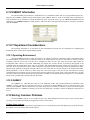
2.12 USBKEY Information.....................................................................................................................................................60
2.13 IT Department Considerations.........................................................................................................................................60
2.13.1 Operating Environment...........................................................................................................................................60
2.13.2 USBKEY................................................................................................................................................................60
2.14 Solving Common Problems.............................................................................................................................................60
2.15 Notes................................................................................................................................................................................64
Copyright Notice
Copy right 2007 - 2011 Malaquite Corporation
All Rights Reserved.
Any technical docum entation that is m ade available by Malaquite Corporation is the copy righted work of Malaquite Corporation and is owned by Malaquite Corporation.
NO WARRANTY. The technical documentation is being delivered to y ou AS-IS and Malaquite Corporation makes no warranty as to its accuracy or use. Any use of the technical docum entation or the
information contained therein is at the risk of the user. Docum entation may include technical or other inaccuracies or ty pographical errors. Malaquite Corporation reserves the right to make changes without prior
notice.
No part of this publication m ay be copied without the express written permission of Malaquite Corporation, 3636 S Alameda #B-177, Corpus Christi, TX 78411.
Trademarks
Microsoft, and Windows are registered tradem arks of Microsoft Corporation. Other product nam es m entioned in this m anual may be tradem arks or registered trademarks of their respective companies and are
hereby acknowledged.
Copyright Malaquite Corporation 2011. All rights reserved.
AdvancedDAS Installation Instructions
INTRODUCTION
AdvancedDAS 1.9 is an automated data acquisition and report generation program designed for use with ECOM J2KN and
ECOM EN2 emission analyzers and is capable of communicating with these analyzers using either a Bluetooth serial link, direct
connection USB link, or, for the J2KN, a USB-HF radio link. This program is written to run under the Microsoft Windows XP and
Windows 7 operating systems. This program utilizes a USB Flash drive as a USBKEY for program distribution and for program
execution authorization.
This manual consists of two sections. The first section addresses details and procedures needed to install the program on a
target PC. The second section addresses operation of the AdvancedDAS program. The user is urged to read this manual completely
before beginning installation or operation of the program.
1 INSTALLATION INSTRUCTIONS
Following are instructions to guide the user through the process of installing AdvancedDAS and its associated components on
a PC. The user is strongly urged to read these instruction through completely before attempting any of the procedures.
Installation of the AdvancedDAS product onto a target PC involves seven basic steps. These are 1) if needed, USB driver
installation, 2) if needed, installation of the Bluetooth radio, 3) installation of the analyzer USB, USB-HF Radio, or Bluetooth
communications device, 4) installation of the AdvancedDAS software, 5) configuration of the analyzer communcation port(s), 6)
registration of the AdvancedDAS USBKEY, and 7) locating the analyzer COM port on the host PC.
1.1 System Requirements
The AdvancedDAS application and associated USB drivers are designed to function with Windows XP SP2 or later and
Windows 7. The drivers will not function with Windows 95, 98, Me, or 2000 therefore, AdvancedDAS will not function with these
versions of Windows. The target PC will need to have a hard drive with at least 15MB of space for the application. It is recommended
that the target PC have at least 100MB of hard drive space for this application in order to accomodate test report storage. Installation
of AdvancedDAS onto a FLASH drive is not recommended. The target PC is recommended to have at least 512MB of RAM for
Windows XP and 3GB of RAM for Windows 7, and must have two USB 2.0 ports available for connection to the analyzer and the
USBKEY, a mouse pointing device, display of 800x600 or greater in resolution, and,optionally, a Class 1 Bluetooth adapter for
communication to a Bluetooth equipped analyzer. The user is strongly urged to disable the System Standby and System Hibernate
functions on the target PC to avoid a possible loss of data during an emissions test. It is also necessary for the PC to have read, write
and execute access to a USB flash drive enabled.
1.2 Analyzer-PC Communications System Installation
There are several mechanisms available to link an ECOM analyzer to a host PC that will be running the AdvancedDAS
program. For the J2KN analyzer, a USB-linked 900 Mhz USB-HF Radio, a direct connect USB link, or a Bluetooth Radio supplied
serial link may be used depending upon how the associated analyzer is equipped. For the EN2 analyzer, a direct connect USB link, or
a Bluetooth Radio supplied serial link may be used depending upon how the associated analyzer is equipped. Contact your ECOM
representative to determine which communications link(s) are available on your particular analyzer. Following is a summary of the
steps in the analyzer-PC communcations system installation for USB or USB-HF radio and Bluetooth communications links.
For analyzers that will use either a 900 Mhz USB-HF Radio, or a direct connect USB link, a set of Silicon Labs CP210x USB
drivers must be pre-installed on the host PC before the radio or analyzer can be connected to the host PC. After these drivers have
been pre-installed on the host PC, the USB-HF radio or analyzer USB port may be connected to the host PC. This action will trigger
the operating system Found New Hardware Wizard which will associate the pre-installed USB drivers with the new device and will
assign a new COM port number to the USB-HF radio or analyzer USB port. Beginning in section 1.3, detailed instructions are
provided on how to accomplish this.
For analyzers that will use a Bluetooth radio to link to the PC, a suitable Bluetooth protocol stack must be installed on the
host PC, a suitable Class 1 Bluetooth USB adapter must be connected to the host PC and registered, and a successful pairing of the
analyzer's Bluetooth radio and a COM port on the host PC must be completed. Host PCs that run Windows XP SP2 (Service Pack 2)
or later, and PCs that run Windows 7 have the Microsoft Bluetooth protocol stack already as part of their operating system. The
Microsoft Bluetooth protocol stack is the only supported choice for AdvacnedDAS, and is what is shown throughout this manual. Any
PC planned for use with AdvancedDAS using a Bluetooth radio must be upgraded as needed to have the Microsoft Bluetooth protocol
1
Copyright Malaquite Corporation 2011. All rights reserved.
AdvancedDAS Installation Instructions
stack. Later sections of this manual describe how to select a suitable Bluetooth radio adapter and how to go about pairing the
Bluetooth radio in the analyzer with a COM port on the host PC.
1.3 Driver Installation for J2KN USB-HF Radio & J2KN/EN2 Direct Connect USB
Before connecting a USB-HF radio, J2KN USB port, or EN2 USB port to a PC for the first time, the USB drivers for those
devices must be pre-installed on that PC. All these devices use the same USB driver. It is recommended that the target PC be
disconnected from the Internet and from any corporate computer network before proceeding. The driver installation process includes
scanning the target PC for previous driver installations. In the event that the target PC is connected to a computer network, two
undesirable things will probably happen. These are 1) all the network drives will be scanned for prior USB-HF driver installations
which may upset or alarm the network manager, and 2) the installation process will take a very very long time to complete. If the
target PC is to be disconnected from a network for this installation, it is best to reboot the PC after network disconnection so that all
network drives will be properly reported as disconnected.
If the target PC is connected to the Internet or the USB-HF radio or J2KN or EN2 is connected to the target PC before the
drivers have been pre-installed, the operating system may install the wrong USB drivers as a result. If that occurs, the USB driver will
have to be replaced with the proper driver.
If the AdvancedDAS program is being installed on a host PC that already has a working copy of AdvancedDAS that is able to
communicate with an ECOM J2KN or EN2 analyzer via either a direct connect USB link or a USB-HF radio, there is no direct need to
install new USB drivers on the host PC. New drivers may be installed on this PC, however, doing so may result in the failure of the
existing program to communicate with the analyzer. Similarly, if the host PC is used to link to other types of test, diagnostic, or engine
control equipment using the Silicon Labs CP210x USB driver, upgrading the driver for the AdvancedDAS program could cause this
equipment to cease communication with the host PC. The user should consult with the vendors for these other devices to determine
whether or not a USB driver upgrade will interfere with their product's normal operation. The only exception to this is if a Windows 7
PC is running version 5.0.0.0 of the USB driver. This version of the driver is not suitable for use under Windows 7 and must be
upgraded. Failure to do so can result in unexpected failure of the communications link with consequent loss of test data and value
testing time.
SPECIAL UPGRADE NOTE! ---- READ THIS!
If this is an upgrade on a host PC that already communicates with an ECOM J2K(N) via
a USB-HF radio or direct USB connection or to an EN2 analyzer via direct USB connection, the
USB Driver Installation step may not be required.
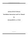
The easiest way to pre-install the USB drivers is to run the AdvancedDAS installation program named setup.exe on the
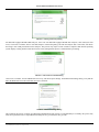
USBKEY. The following series of screen-shots illustrate the USB driver pre-install sequence under Windows XP. The process under
Windows 7 is very similar. When the installation application starts, you will see the splash screen shown below.
Opening Splash Screen
Click NEXT to continue. The main screen of the installer then appear.
2
Copyright Malaquite Corporation 2011. All rights reserved.
AdvancedDAS Installation Instructions
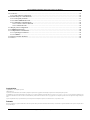
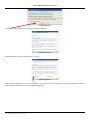
Installer Main Screen
Click the 1) INSTALL USB Drivers button to launch the USB Driver Pre-Installer. The notice shown below will then appear.
USB Pre-Installer Notice Screen
Click YES to continue.
A dialog similar to that shown below will appear in response.
USB-HF Radio Driver Pre-Installer Dialog
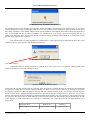
Click Install to choose the default location and continue. Shortly afterward, the message shown below will appear reporting that the
installer is scanning the target PC for prior installations of the USB driver.
3
Copyright Malaquite Corporation 2011. All rights reserved.
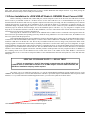
AdvancedDAS Installation Instructions
USB-HF Radio Driver Pre-Installer Scanner Pop-Up
The scanning process will take anywhere from seconds to minutes to complete. Be patient and do not interfere with or try to stop this
process! The installer is simply scanning all available drives for prior installations of the USB driver. At the end of this search, one of
three things will happen. 1) The installer will have found no prior installation of the USB-HF driver and will begin copying the driver
files. 2) The installer will find an existing installation of a USB-HF driver of the wrong version and will prompt the user for
permission to change the driver version. 3) The installer will find an existing installation of the USB-HF driver of the proper version
and will simply inform the user of that fact.
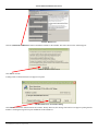
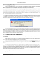
If the installer finds no existing installation of a USB-HF driver, it will begin copying and registering the driver files. Upon
completion, the user will be presented with the dialog shown below.
USB-HF Radio Driver Pre-Installer Complete Dialog
Click OK to continue.
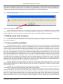
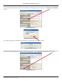
If the installer finds an existing installation of a USB-HF driver of the wrong version, it will present a dialog similar to that
shown below asking for permission to change the driver.
Incorrect USB-HF Radio Driver Notice
At this point, the user must consider what do to carefully. If the wrong driver is found on the target PC because the user installed the
wrong driver accidently, then it is correct to click YES and have the driver version corrected. If, however, the wrong driver is found on
the target PC because some other USB device of the same PID/VID is already installed, the user most consider what will happen to
that device if this driver is changed. Installing the new driver in this situation can cause the other device(s), whatever it is, to no longer
function while allowing the new ECOM device to function normally. In this situation, only one of the devices can be used on the target
PC at one time. The user will have to decide which device that will be and either click YES and allow the new ECOM device to work
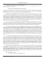
on the target PC or install AdvancedDAS on a different PC. Additionally, only certain drivers may be run under Windows 7 as is
shown below:
Operating System
Suitable USB Driver Versions
Windows XP
Windows 7
5.0.0.0, 5.4.24.0, 6.1.0.0
5.4.24.0, 6.1.0.0
4
Copyright Malaquite Corporation 2011. All rights reserved.
AdvancedDAS Installation Instructions
As the above table indicates, version 5.0.0.0 is not suitable for use under Windows 7. If this version is found to be installed on a
Windows 7 PC, it must be upgraded even at the cost of having other programs fail since running version 5.0.0.0 under Windows 7 can
result in unexpected failure of the communications link with consequent loss of test data and valuable time.
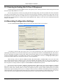
If the installer finds an existing installation of the USB-HF driver of the proper version on the target PC, a dialog similar to
that shown below will be presented.
Correct USB-HF Radio Driver Notice
In this situation, simply click OK to continue.
Having reached this point without any error messages, the USB driver files for the new ECOM analyzer have been installed
on the target PC. You will then be returned to the AdvancedDAS Installation Program dialog to proceed with the installation of the
program components. If you received any error message prior to this point, contact technical support for further help.
1.3 USB Bluetooth Radio Installation
For users who plan to use the Bluetooth radio to link the analyzer to the PC, a suitable device must be selected, and obtained.
The device must then be connected to the host PC to allow the host PC operating system to register the device and load the necessary
device drivers for the radio.
1.3.1 Choosing A Bluetooth Radio
Most Bluetooth adapters utilize the USB system to physically link to the host PC. Of these, there are two USB standards that
the adapter might use. These are USB 1.1 and USB 2.0. Although this choice is not critical, the user should try to find a device that
supports USB v2.0. More importantly, Bluetooth devices are designed to function at one of three standard power levels. These power
levels are roughly correlated to the maximum achievable range that the device can communicate over and are referred to as a Class of
device. These device classes are Class 1 with approximately 300' maximum range, Class 2 with approximately 30' maximum range,
and Class 3 with approximately 3' maximum range. The Bluetooth adapter installed on the ECOM EN2 is a Class 2 device. The
Bluetooth adapter installed on the ECOM J2KN is a Class 1 device. The Bluetooth adapter chosen for use on the host PC should be a
Class 1 device and should utilize an external antenna. A Class 1 one device is highly recommended as such a device will have a much
more higher transmit power level. Secondarily, a Class 2 device may be used, however doing so will result in diminished range
especially if the device is packaged in a micro-housing. Under no circumstances should the user attempt to use a Class 3 device as this
type of device has extremely limited range of less than 3 feet. Some PCs have a Bluetooth device built-in. Users whose PC has a builtin Bluetooth radio, will need to consult the PC specifications to determine what Class of Bluetooth device is installed and whether or
not this device can be disabled to allow an external device to be utilized if needed.
Bluetooth adapters are designed to support many different types of operations such as linking a keyboard or mouse to the
host, or providing an audio link to a headset, a link to a network, etc. Each of these operations is referred to as a service. When
selecting a Bluetooth adapter for use with an ECOM analyzer, the user should be sure that the device is capable of supplying the SPP,
Serial Port Profile, service.
Although this is not an endorsement, the model GBU321 Class 1 Bluetooth 2.0 USB Adapter made by IOGEAR has been
used with success with various laptops running under either Windows XP or Windows 7.
In the event that a user already has a Bluetooth device for linking to a wireless mouse or wireless keyboard or other device
installed on the target PC, this device may also be able to support a connection to the analyzer. In such a case, the user will need to
consult the specifications and software instructions for the device to determine if it can support an SPP and to determine what Class
the device is. If SPP is supported and the power level is sufficient, the user may want to simply enable SPP service on this device,
search for the analyzer and pair with it to generate a VCP for the AdvancedDAS program to use. However, if the existing Bluetooth
adapter is insufficient in some way, the user will have to consider replacing it with a more suitable device. This will involve un-
5
Copyright Malaquite Corporation 2011. All rights reserved.
AdvancedDAS Installation Instructions
installing the wireless devices currently supported by the device to be replaced, un-installing the Bluetooth adapter itself and possibly
un-installing the associated Bluetooth stack. The users IT department or the manufacturer of the new device with have to be consulted
to determine exactly what steps will be needed. Afterward the new Bluetooth adapter and software may be installed along with the
SPP and any other services needed to link to existing wireless devices.
1.3.2 Bluetooth Protocol Stack
The Bluetooth protocol stack is a large collection of programs that provide all the functionality of the various services offered
by the Bluetooth adapter. These services include such things as remote network access, wireless mouse and keyboard capability, a
wireless serial link, various types of audio links, etc. A Bluetooth stack must be installed on a PC that uses a Bluetooth adapter. There
are several such stacks available and until the release of Service Pack 2 (SP2) of Windows XP, one of these stacks had to be obtained
and loaded in order to use a Bluetooth device on a PC. However, with Windows XP SP2 or later and with Windows 7, a Microsoft
Bluetooth protocol stack is a default part of the Windows operating system and it is no longer necessary to load a third-party stack.
Additionally, the Microsoft Bluetooth protocol stack is the stack that must be used with AdvancedDAS.
When installing a Bluetooth adapter, the user may discover that the adapter's vendor may have supplied a distribution CD that
contains one of the alternate Bluetooth protocol stacks. If such a situation occurs, the user should not install the alternate Bluetooth
protocol stack in addition to or in place of the default Windows Bluetooth stack. Typically, all that is needed from the vendor's
distribution CD are adapter device drivers. However, even many of those are now part of the Windows operating system.
Special Note Regarding The Installation Of The Bluetooth Protocol Stack
For PCs running Windows XP SP2 or later or Windows 7, it is typically not necessary to install the Bluetooth Protocol
Stack supplied with the Bluetooth adapter as these versions of Windows include a Microsoft Bluetooth stack. Trying to
install a Bluetooth stack in addition to the Microsoft stack will greatly complicate the Bluetooth link configuration and
can result in a failure of the Bluetooth system on the target PC. Read the UP-TO-DATE Bluetooth vendor manual
carefully to determine whether or not installation of an additional Bluetooth stack is required for the chosen adapter. Note
that Bluetooth adapters that were manufactured before the release of Windows XP SP2 will state that a Bluetooth stack
must be installed on the target PC because before SP2 of XP, Windows did not include a Bluetooth stack. If you are
unable to resolve this issue, assume that a new Bluetooth stack is not required and proceed with the installation of the
USB Bluetooth adapter drivers without the new Bluetooth stack.
1.3.3 Choosing The USB Port For The Bluetooth Radio
Most USB devices or appliances can be plugged into any USB port on a host computer without any impact on the proper
function of the device or appliance. However, that is not so where a USB Bluetooth adapter is concerned. The USB Bluetooth adapter
must be plugged into the same USB port on the host PC each time it is used. Plugging a USB Bluetooth adapter into a port other than
the one used during it initial loading will result in a new device registration procedure and the assignment of new device assignments.
In the case of Bluetooth-linked analyzers, moving the USB Bluetooth adapter to a different USB port can result in the analyzer COM
port assignments being changed.
Therefore, once a USB port is chosen for the Bluetooth adapter, it must always be used for the Bluetooth adapter. Before
choosing a USB port for the Bluetooth adapter, one should try to select a port which will allow the Bluetooth adapter to be clear of
nearby objects which may interfere with the radio signal from the adapter.
Additionally, if an external USB hub will be used to supply a port for the Bluetooth adapter, a port on that hub must be set
aside for the Bluetooth adapter only and the USB hub itself must be connected to the same USB port on the host PC each time the hub
and Bluetooth adapter are used for the same reason listed above.
6
Copyright Malaquite Corporation 2011. All rights reserved.
AdvancedDAS Installation Instructions
VERY IMPORTANT!
The USB port used for the Bluetooth adapter should be physically marked so that the Bluetooth adapter can
always be plugged into the same port each time it is used. Similarly, if an external USB hub is used to
provide a USB port for the Bluetooth adapter, the port on the external hub used for the Bluetooth adapter
should be physically marked and the USB port on the host PC used for the external USB hub should be
marked to ensure that both the hub and Bluetooth adapter are connected to the same structure on the host
PC's USB subsystem.
1.3.4 Installing The USB Bluetooth Adapter
After having selected a Bluetooth adapter and deciding which USB port to connect it to, the recommended procedure for
installing the Bluetooth adapter is simply to plug it into the host PC at the chosen USB port. Windows XP SP2 or later or Windows 7
should have little or no trouble identifying the device and loading the proper drivers. In some cases, it may be necessary to use the
Bluetooth adapter's distribution CD to obtain device drivers or it may be necessary to connect to the Internet to obtain needed device
drivers for the adapter. After the device is initially installed, the operating system will then setup some basic Bluetooth services for the
device. This process may require many seconds to complete. At the completion of this process, the operating system will report that
the device is installed and ready to use.
7
Copyright Malaquite Corporation 2011. All rights reserved.
AdvancedDAS Installation Instructions
1.4 Install Analyzer Communications Device
After having pre-installed the USB drivers or having installed the USB Bluetooth radio, it is necessary to install the actual
communications device that will link the analyzer to the AdvancedDAS program. This step will involve connecting the analyzer
communication equipment, the USB-HF radio, the J2KN USB port, or the EN2 USB port to the PC so that the operating system can
register the device. Alternately, for a Bluetooth radio link, this step will involve pairing a COM port on the host PC with the the J2KN
Bluetooth device, or the EN2 Bluetooth device. For the USB-HF radio and the J2KN and EN2 USB port, this is a simple process as
explained in sections 1.4.1 and 1.4.2 below. For the J2KN and EN2 Bluetooth device, this is a more involved process as described in
1.4.3 below.
1.4.1 Install the J2KN USB-HF Device
Installation of the J2KN USB-HF radio device may only take place after the USB driver has successfully been pre-installed
on the target PC. If the USB driver is installed, install the new device by connecting a USB cable from the USB-HF radio to the target
PC. Wait for Windows to recognize the device and install it automatically. This process may take many seconds and in rare cases,
several minutes. Upon successful completion, Windows will display a message clearly stating that the new device is installed and
ready for use.
1.4.2 Install the J2KN or EN2 USB Port Device
Installation of the J2KN or EN2 USB port device may only take place after the USB driver has successfully been preinstalled on the target PC. Note that the J2KN and EN2 USB port utilizes the same drivers as the USB-HF radio. If the USB driver is
installed, install the J2KN or EN2 USB port device by connecting a USB cable between the analyzer USB port and the target PC. Wait
for Windows to recognize the device and install it automatically. This process may take many seconds and in rare cases, several
minutes. Upon successful completion, Windows will display a message clearly stating that the new device is installed and ready for
use.
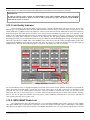
1.4.3 Install J2KN or EN2 Bluetooth Device
After successfully installing the new Bluetooth radio, a new communications port that is linked to the Bluetooth-equipped
ECOM analyzer can be created. With the Bluetooth adapter connected to the host PC, begin by turning the analyzer ON and placing it
near the host PC. Next, left click the Bluetooth icon in the desktop tray in the lower right corner of the PC display and choose Show
Bluetooth Devices.
Bluetooth Icon
A dialog similar to that shown below will appear.
Windows 7 Show Bluetooth Devices Dialog
8
Copyright Malaquite Corporation 2011. All rights reserved.
AdvancedDAS Installation Instructions
The Show Bluetooth Devices dialog will be blank, as shown above, if no Bluetooth devices have been setup on the host PC. However,
if an ECOM analyzer or other Bluetooth device has already been setup on the host PC, an object will be displayed on this dialog for
each device already setup. Additionally, each of these objects will have associated text that reads “Passkey enabled” located under the
object. If the target analyzer is already setup on the host PC, there is no need to setup additional instances of the connection. If the
target analyzer is not setup on the host PC, regardless of whether or not other devices are setup, proceed with the steps below.
Be sure that the ECOM analyzer to be connected to is turned ON and is located near the host PC with the new Bluetooth
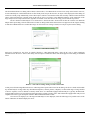
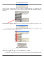
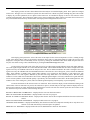
adapter before proceeding. Click the Add A Device button. A dialog similar to that shown below will appear as the PC begins scanning
to find all new Bluetooth devices within radio range. As each new device in range is found, a new object is placed on this dialog.
Windows 7 Add A Device Dialog
Each newly found device may show up initially labeled as “Other Bluetooth Other” while the PC tries to gather identifying
information from the device. After a short delay, more descriptive information about each should appear on this dialog as illustrated
below.
Windows 7 Add A Device Dialog Listing A Printer And A J2KN
At this point, all functioning Bluetooth devices within range that respond will be listed in this dialog. The devices listed could include
any ECOM analyzer in range and/or any other Bluetooth printers, cameras, phones, computers, etc that within range. If a large number
of devices respond, it can be difficult to identify which device is a Bluetooth-equipped ECOM analyzer. Typically, the Bluetoothequipped J2KN analyzer will respond with a description that is similar to FireFly-94CC and a Bluetooth-equipped EN2 analyzer will
respond with a more cryptic description similar to BNC4-D0A5000018DA 'COM1'.
If no devices are displayed, or if the target ECOM analyzer is not displayed, check the following list of possible causes of the
failure of Windows to find and display the device.
9
Copyright Malaquite Corporation 2011. All rights reserved.
AdvancedDAS Installation Instructions
Causes of the failure of Windows to find and display the device, with Remedies
1. The target device is too far away from the host PC's Bluetooth adapter antenna. Remedy:
Move the target device to a position that is closer to the PC.
2. The target device does not have a Bluetooth radio installed. Remedy: Verify that the target
device has a Bluetooth radio installed.
3. The target device is turned OFF. Remedy: Turn the target device ON.
4. The target device has already been paired on the host PC. Remedy: Click the Bluetooth icon in
the desktop tray and choose Show Devices. Examine the list of devices shown to determine if
the target analyzer has already been paired on the host PC.
5. The target device is currently connected to or is being queried by another PC or computing
device such as a smart phone. Remedy: Be sure other PCs are not connected to the target
device and turn OFF any smart phones in range of the target device.
6. The target device was recently connected to a different PC. Remedy: Be sure the previously
used PC is OFF, then turn the target analyzer OFF and then ON to break the connection to the
other PC.
Assuming that the target device is listed on the Add A Device dialog, click on the desired device, FireFly-94CC in this
example, and click Next to continue. The PC will then try to begin a pairing procedure where a particular Bluetooth radio, the one
installed in the ECOM analyzer, will be paired with a particular COM port on the host PC. This process will require uninterrupted
communication between the host PC and the target analyzer. If communication can be established, a dialog similar to that shown
below will appear.
Windows 7 Pairing Code Dialog
If the PC cannot establish communication with the target analyzer, an error message will be displayed. In most cases when this occurs,
the user shown simply return to the Add A Device dialog and try to again by clicking the target device and clicking Next. The device
will normally respond after two or three attempts.
If communication can be established with the target analyzer, click Enter the device's pairing code. A dialog similar to that
shown below will appear requesting the device's pairing code.
10
Copyright Malaquite Corporation 2011. All rights reserved.
AdvancedDAS Installation Instructions
Windows 7 Pairing Code Entry Dialog
For Bluetooth-equipped ECOM J2KN analyzers, enter 1234. For Bluetooth-equipped ECOM EN2 analyzers, enter 0000 (enter four
zeros). Click Next to continue. The PC will then attempt to confirm the pairing code with the analyzer and, if successful, will choose
and assign a new COM port number for this analyzer. This process may require several seconds to complete. Wait until the operating
system displays a dialog similar to that shown below clearly stating that the process is finished before proceeding.
Windows 7 Add A Device Finished Dialog
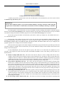
Click Close to continue. Left click Bluetooth icon in tray, and choose Open Settings. On the Bluetooth Settings dialog, verify that the
Show the Bluetooth icon in the notification area item is checked.
Windows 7 Bluetooth Settings Dialog
This completes the process of setting up a Bluetooth communications link, pairing, to an ECOM analyzer. Normally, this process only
needs to be performed once to setup a Bluetooth COM port for a given analyzer on a given PC.
11
Copyright Malaquite Corporation 2011. All rights reserved.
AdvancedDAS Installation Instructions
1.5 AdvancedDAS Software Installation
Follow the instructions below to load the ECOM AdvancedDAS application software onto the target personal computer. Note
that the application will not run directly from the USBKEY!
Stop or close all programs on the target PC before beginning this installation. If the USB drivers have not yet been installed
on this PC, return to the USB Driver Installation instructions and DO NOT PLUG THE USB-HF INTO THE PC UNTIL DIRECTED
TO DO SO!!
If this is an upgrade, backup the existing ECOM_DAS folder and all its contents before starting the upgrade. Insert
the AdvancedDAS USBKEY into one of your PC's USB ports and wait for the operating system to register the device. Afterward, start
the installer by opening the USBKEY drive and double-clicking the setup.exe file or start the installer manually by clicking the
START button and choosing RUN. Enter D:\setup.exe and click OK. In place of the character D, substitute the proper drive letter for
the USBKEY.
Follow the instructions shown on each screen of the installation guide. Read each screen and note carefully. The installation
guide will automate the process of installing your new software or upgrading your software. It is recommended that the AdvancedDAS
software be installed in the target PC's My Documents folder under Windows XP and under the user's folder under Windows 7. For
example, under Windows 7, if the user name is jsmith, the AdvancedDAS software should be installed at the following location
C:\Users\jsmith\. Alternately for Windows 7, the AdvancedDAS program may be installed in the Public folder located at
C:\Users\Public\. Be aware that you may have to have administrative privileges to install this program under Windows 7.
The following is a typical sequence of installation screens copied during the installation of AdvancedDAS. Click NEXT to
continue.
Opening Splash Screen
Installer Main Screen
Click INSTALL AdvancedDAS button to start the installation process or click Close to abort the installation.
12
Copyright Malaquite Corporation 2011. All rights reserved.
AdvancedDAS Installation Instructions
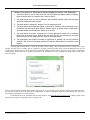
Initial Instructions
Click OK to continue. The License Agreement will then be displayed.
License Agreement
Read the agreement carefully, scrolling down as you read.
License Agreement
At the end of the agreement text, click on "ACCEPT" if you accept the terms of the agreement to continue the installation. You will
then be returned to the main screen of the installation application.
13
Copyright Malaquite Corporation 2011. All rights reserved.
AdvancedDAS Installation Instructions
Installer Main Screen
Continue the installation by clicking SELECT LOCATION FOR INSTALLATION.
Installation Location Selection Dialog
In the dialog above, left click on the selector box directly under the words "Select Target Drive" and choose the hard drive for your
computer. For most computers, c:[] is the proper choice.
Installation Location Selection Dialog
After selecting the proper drive, c:[] in this case, double click on the c: icon in the "Installation Location" box to open a view of the
contents of the c: drive.
14
Copyright Malaquite Corporation 2011. All rights reserved.
AdvancedDAS Installation Instructions
Installation Location Selection Dialog
In the tree listing that appears, search for the entry "documents and settings" and double click that entry. In the documents and settings
folder, choose the entry for your current account. Typically, this will be your name. Double click on the folder for your current account
to open it.
SPECIAL UPGRADE NOTE! ---- READ THIS!
If this is a new installation, continue with the instructions below. If this is an upgrade
installation, skip ahead to the 1.5.1 Completing Upgrade Installation instructions.
Within your account folder, find the folder named "my documents" and double click that folder to open it.
After double clicking on “my
documents”, click OK to
continue.
Installation Location Selection Dialog
Next, click the OK button to continue.
15
Copyright Malaquite Corporation 2011. All rights reserved.
AdvancedDAS Installation Instructions
After having selected a destination location for the installation, the dialog shown below will appear. Click INSTALL SOFTWARE to
continue.
Installer Main Screen
Installation Folder Name Dialog
The confirming dialog for the installation folder name above will then appear. Click OK to continue.
File Copy Progress Pop-Up
The message above will appear as the files are being copied onto your PC. After all the application's files have been copied onto your
computer, the installation application will display the dialog shown below. Click "COMPLETE INSTALLATION" to continue.
Installer Main Screen
16
Copyright Malaquite Corporation 2011. All rights reserved.
AdvancedDAS Installation Instructions
Software Installation Complete Dialog
At this point, the new software has been installed. If there is a Readme file, the dialog above will appear. You are urged to review the
Readme file before proceeding. After reading this file, close the NotePad application that is used to display the Readme file.
The new software installation process is now complete.
1.5.1 Completing Upgrade Installation
If this is an installation of an upgraded copy of this software, it will be necessary to show the installer where the current
installation is located. Assuming that current installation is located in the user's My Documents folder as suggested, the following
instructions will guide the user through the process of locating the current installation.
Installation Location Selection Dialog
Within your account folder, find the folder named "my documents" and double click that folder to open it. Within the My Documents
folder, locate the current installation of AdvancedDAS and left click once on that folder.
Notice that the
selected folder
appears to be an
existing installation.
Current Installation Folder
The installer will automatically scan the contents of that folder to determine is a copy of AdvancedDAS.exe exists within that folder. If
this file is found, the installer will display the message shown above in red to let the user know that the selected folder appears to be a
current installation of AdvancedDAS. If this is the installation to be upgraded, click the OK button at the top of the dialog. The dialog
17
Copyright Malaquite Corporation 2011. All rights reserved.
AdvancedDAS Installation Instructions
shown below will appear asking the user to confirm the upgrade location.
Upgrade Location Confirmation
Click Yes to continue. The re-confirmation dialog shown below will be presented to allow the user one additional opportunity to verify
the upgrade location.
Upgrade Location Confirmation
Click Yes to continue. The installer will present the dialog shown below to backup the existing installation.
Backup Existing Installation Step
Click BACK-UP EXISTING INSTALLATION to continue. Doing so will cause the existing installation folder to be renamed
ECOM_DAS_Backup. Afterward, the dialog shown on the following page will appear.
INSTALL SOFTWARE Step
Click INSTALL SOFTWARE to continue. The new software will then be copied from the CD onto the host PC and the notice shown
below will be presented to the user.
18
Copyright Malaquite Corporation 2011. All rights reserved.
AdvancedDAS Installation Instructions
After the new software has been copied to the host PC, the installer will present the dialog shown on the following page. In the
following upgrade step, the installer will copy the contents of the original installation's DATA folder into the upgrade installation's
DATA folder.
Click COPY DATA to continue. The installer will then copy the existing data into the new installation and will present the notice
shown below while that copy process is running.
After all the application's files have been copied onto your computer, the installation application will display the dialog
shown below. Click "COMPLETE INSTALLATION" to continue.
Software Installation Complete Dialog
At this point, the new software upgrade has been installed.
1.6 Configuring The Analyzer For Use With AdvancedDAS
An ECOM J2K(N), J2K(N) IND, or EN2 analyzer must be properly configured before it can be used with the AdvancedDAS
19
Copyright Malaquite Corporation 2011. All rights reserved.
AdvancedDAS Installation Instructions
program. This configuration process involves setting certain entries in the analyzer using the analyzer's keypad and LCD display. Once
these configuration settings have been made, they are retained in the analyzer memory permanently.
1.6.1 Configuring the J2K(N)/IND Analyzer
In order for AdvancedDAS to work with a standard J2K(N) or J2K(N) IND, the analyzer's hand-held remote and base unit
firmware must be version 2.3 and 2.4, respectively, or later. The firmware version of the hand-held remote and base unit may be
determined by viewing the “Program Version” line on the Control menu on the hand-held remote. This line will report this
information in the form Vx.y day.month.year / w.z, where Vx.y is the version of the hand-held remote firmware and its release date,
and w.z is the version of the base unit firmware. The firmware in the USB-HF radio used with the analyzer must be version 1.7 or
later. Contact ECOM technical support to determine the version of firmware in the USB-HF radio.
Provided that the analyzer has the proper version firmware, use the hand-held remote and beginning with the Main Menu,
navigate through the following sequence of menus,
Main Menu -> Adjustments -> Internal -> RF-connect. only
Once in the RF-connect. only menu, use the UP or DOWN keys to select the Remote option. Afterward, use the menu key to return
the the Main Menu and to normal Gas Analysis.
In order to use the J2KN's Bluetooth or direct connect USB ports, two additional sets of configuration settings must be set.
One set is for the Bluetooth radio port and the other is for the USB port. Using the analyzer keypad and starting from the Main Menu,
navigate through the following sequence of menus,
Main Menu -> Adjustments -> Internal -> Bluetooth
Once in the Bluetooth menu, use the LEFT and RIGHT arrow keys to select the Protocol Enhanced selection. The BAUD rate for the
Bluetooth port is fixed at 9600 BAUD. After completing this setting, press the Menu key to return to the Adjustments menu and then
select the USB menu items or use the sequence below to navigate to the USB menu from the Main Menu.
Main Menu -> Adjustments -> Internal -> USB
Once in the USB menu, use the UP and DOWN arrow keys to choose the 38400 BAUD selection, then use the LEFT and RIGHT
arrow keys to select the Protocol Enhanced selection. After completing these settings, use the Menu key to return to the Main Menu.
1.6.2 Configuring The EN2 Analyzer
For the EN2, two sets of configuration settings must be set. One set is for the Bluetooth radio port and the other is for the
USB port. Using the analyzer keypad and starting from the Main Menu, navigate through the following sequence of menus,
Main Menu -> Adjustments -> Bluetooth
Once in the Bluetooth menu, use the LEFT and RIGHT arrow keys to select the Protocol Enhanced selection. The BAUD rate for the
Bluetooth port is fixed at 9600 BAUD. After completing this setting, press the ESC key to return to the Adjustments menu and then
select the USB menu items or use the sequence below to navigate to the USB menu from the Main Menu.
Main Menu -> Adjustments -> USB
Once in the USB menu, use the UP and DOWN arrow keys to choose the 38400 BAUD selection, then use the LEFT and RIGHT
arrow keys to select the Protocol Enhanced selection. After completing these settings, press the ESC key 4 times to return to the Main
Menu.
20
Copyright Malaquite Corporation 2011. All rights reserved.
AdvancedDAS Installation Instructions
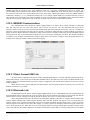
1.7 Registering The AdvancedDAS USBKEY
The AdvancedDAS program utilizes a USB Flash drive, the USBKEY, for program execution authorization as well as for a
distribution media. In most cases, this USBKEY must be registered with Malaquite Corporation before the program can be used.
AdvancedDAS kits shipped directly fom Malaquite Corporation are typically registered before shipment. USBKEY registration is
accomplished by contacting Malaquite Corporation by email or telephone and requesting a registration key code. Malaquite Corp will
require the following information in order to create a registration key code for AdvancedDAS:
•
•
•
•
•
•
•
•
•
USBKEY Serial Number
ECOM Analyzer Model
ECOM Analyzer Serial Number
ECOM Analyzer Electrochemical Cell Configuration
Client Company Name
Client Contact Name
Client Contact Shipping Address
Client Contact Phone Number
Client Contact email Address
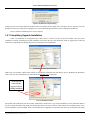
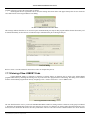
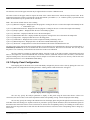
The registration key code is a 40 character code arranged into 8 groups of 5 characters. This code must be entered into the ENTER
NEW KEY CODE box of the View Program Status Codes dialog.
Until the USBKEY is registered, the following error will appear each time that the AdvancedDAS program is started.
USBKEY Not Initialized Error
When the OK button of this dialog is clicked, the View Program Status Codes dialog shown below will appear to allow the user to
enter the Malaquite Corp supplied Key Code.
View Program Status Codes Dialog
The user should enter the new key code in the ENTER NEW KEY CODE box starting with the 5 characters in the group box labeled
1. The dialog will automatically switch to the next group box as each set of 5 characters are entered. After all 40 characters have been
entered, the user should click the Process New Key Code button. The new code entered will be validated and the user will be notified
of the result in a text message that will appear to the left of the Process New Key Code button. A valid code will result in the following
text message:
Key Code Validated. Click Close to process this new code.
An invalid code will result in an error message. Note that each registration code can only be used on a specific USBKEY and
can only be used once. Attempting to use a registration code on a different USBKEY or attempting to use a code after it has been used
to register a USBKEY will result in an error. If an error is found during initial registration of the USBKEY, the AdvancedDAS
21
Copyright Malaquite Corporation 2011. All rights reserved.
AdvancedDAS Installation Instructions
program will close as soon as the Close button is clicked.
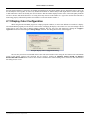
Assuming that the new registration code is valid, the message box shown below will appear shortly after the user clicks the
Close button on the View Program Status Codes dialog.
No Prior Communication Connection Error
This message indicates that there is no record of a prior communications port setup for this program and that the Port Scan utility will
be started immediately to allow the user to find and setup a communications port to the target analyzer.
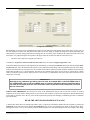
Port Scan Dialog
Refer to section 1.8 of this manual for instructions on how to complete this process.
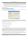
1.7.1 Entering A New USBKEY Code
Certain additional features or functions or changes to existing features or functions can be made to the AdvancedDAS
program authorization by obtaining and entering a new key code in the View program Status Codes dialog. This dialog can be reached
from the AdvancedDAS program main menu by navigating to File->Advanced Functions->View USBKEY Codes.
View Program Status Codes Dialog
The user should enter the new key code in the ENTER NEW KEY CODE box starting with the 5 characters in the group box labeled
1. The dialog will automatically switch to the next group box as each set of 5 characters are entered. After all 40 characters have been
entered, the user should click the Process New Key Code button. The new code entered will be validated and the user will be notified
22
Copyright Malaquite Corporation 2011. All rights reserved.
AdvancedDAS Installation Instructions
of the result in a text message that will appear to the left of the Process New Key Code button. A valid code will result in the following
text message:
Key Code Validated. Click Close to process this new code.
When this code appears, the user should click the Close button, then close and restart the AdvancedDAS program to activate the new
features or settings.
If an invalid code is entered, an error message will result. Note that each registration code can only be used on a specific
USBKEY and can only be used once. Attempting to use a registration code on a different USBKEY or attempting to use a code after it
has been used to register a USBKEY will result in an error.
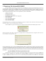
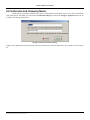
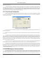
1.8 Locating The Analyzer COM Port On The Host PC
The AdvancedDAS program maintains a record of the last communication port used to link to the target analyzer. Each time
the program is started, this record is read and an attempt is made to re-establish communications with the analyzer via the last port
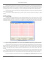
used. The initial and ongoing settings for the communcation port are made semi-automatically using a communication port scanning
utility whose user interface dialog is shown below.
Port Scan Dialog
This dailog is presented automatically when a new installation of the AdvancedDAS program is started or when the user
requests it by navigating from the main menu to File->Advanced Functions->Scan COM Ports. When run, this utility scans every
possible serial communications port on the host PC for the presence of an ECOM analyzer. Information about any analyzer found is
compared to the authorized analyzer information that is stored on the USBKEY. The results of the scan are presented in the table
located at the bottom of the dialog. When desired, the user may change the current COM port to any other port listed provided that the
chosen entry's associated Status value is listed as "OK". In most cases, there will only be one valid choice for connection to an
analyzer.
Before using this utility, the user must have completed the prior steps in the installation process to establish a
communications link between the host PC and the target analyzer. These include:
•
•
•
•
•
•
•
USB Diver pre-installation
USB-HF radio installation and registration
Analyzer USB port installation and registration
Connection of the USB-HF radio or analyzer USB port to the host PC
Bluetooth Adapter installation and registration
COM port/Analyzer Bluetooth radio pairing
Analyzer Communications Configuration
Additionally, the target analyzer must be ON, and connected to the host PC or within Bluetooth radio range. Basically, the analyzer
has to be ready and able to respond to the host PC, when the Port Scan utility tries to communcate with it.
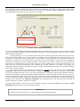
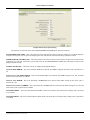
Click the Start Port Scan button to begin the scan process. The scan process will require somewhere between several seconds
23
Copyright Malaquite Corporation 2011. All rights reserved.
AdvancedDAS Installation Instructions
to several minutes to complete depending upon how many ports are setup on the host PC. Note that the scan process will take much
longer for a host PC that has one or more Bluetooth ports setup. Be patient and allow the process to complete normally. After the scan
is complete, a list of all COM ports that have or potentially have an ECOM analyzer connected to them will be listed at the bottom of
the dialog. Only ports listed with a Status value of "OK" may be selected for use by the AdvancedDAS program. Ports that are
connected to an unauthorized analyzer, or ports that did not respond properly may not be used. The user may select a new port for
connection by clicking on the desired entry and clicking the OK button at the bottom of this dialog. After closing this dialog, the user
must close and restart the AdvancedDAS program in order to use the newly selected port.
1.8.1 Common Port Scan Error Messages and Results
In most instances, the results of a port scan will be a single error-free listing of the port that the target analyzer is connected to
and it is a simple matter to select this entry and proceed with normal operation. However, there are several common errors that can
occur during a port scan. Some of these are of no consequence while others require some action on the part of the user. The most
common error occurs when either the analyzer is not properly connected to the host PC, or the analyzer is not properly configured. In
either case, either the port or the analyzer connected to the port fail to respond to the port scan query resulting in the associated port
being ignored and not listed on the port scan dialog. Also common is an error that is reported as error 5 access denied. This error
occurs when the port scan queries a port that is already in use either by the AdvancedDAS program or some other program. The next
most common error is error 121 which is a timeout error related to a Bluetooth linked analyzer. This error occurs when the Bluetooth
radio on the analyzer fails to respond within a preset period of time. Commonly, this is because the associated analyzer is not ON, is
out of range, is connected to another host computer, or because the Bluetooth USB adapter onthe host PC has been plugged into a
USB port other than the USB port used to initially configure it on the host PC.
The following are some common port scan errors and suggestions for their resolution:
Target Analyzer Not Listed
If the target analyzer is believed to be properly connected to the host PC, but no entry for this analyzer is generated as a result of the
port scan procedure, each of the following possible conditions should be checked:
•
Analyzer not configured properly. The analyzer must be in REMOTE mode with Enhanced Protocol selected for both USB
and Bluetooth ports.
•
Analyzer is not connected to the host PC.
•
The analyzer USB port and drivers or Bluetooth adapter or Bluetooth pairing have not been performed.
Error 5
This error results when the Port Scan utility is denied access to a port because the port is already in use by the AdvancedDAS program
or another program. If the AdvancedDAS program is running and is currently connected to an analyzer via the port in question, this
error is normal. However, if a port is in use by another program, the user must determine whether or not that program is connected to
the target analyzer, disconnect it and re-run the Port Scan utility to locate the analyzer. This error can also occur in association with a
Bluetooth supplied port if the Bluetooth adapter is plugged into a USB port other than the port used when the Bluetooth ports were
first setup on the host computer. If this occurs, the user must move the Bluetooth adapter to the USB port at which it was initially
setup.
Error 121
This error results when a Bluetooth supplied port does not respond within a preset time period. Most often, this occurs because some
part of the Bluetooth communications link between the host computer and the target analyzer is not working. This includes, Bluetooth
adapter not plugged into the host computer, target analyzer is OFF, target analyzer is too far away from the host computer, or another
computer is connected to the target analyzer Bluetooth radio, or was connected to the target analyzer recently. The user should be sure
that all equipment is powered ON, and located close together and retry the Port Scan. If the port scan repeatedly shows this error, and
there is reason to believe that the port number is correct, the user should REMOVE and then ADD the target analyzer's Bluetooth port
using the Bluetooth Devices located in the desktop tray of the host computer.
Error 87 or Error 167
These errors can occur when the communications device, USB-HF radio, direct connect USB port, or Bluetooth adapter, are connected
to the host computer via an external USB Hub. If an external USB Hub is used for this purpose, the user should be sure to connect the
external USB Hub to the host computer AFTER the host computer has completed its startup process and the user has logged into the
host computer. Connecting an external USB Hub with any of these analyzer communications devices to the host computer prior to
startup and login can result in either of these errors. These errors can also occur if the user attempts to run more than one Bluetooth
protocol stack on the host computer at the same time. Any PC running Windows XP SP2 or later or running Windows 7 has a built-in
Bluetooth protocol stack and does not need an additional stack installed. If Bluetooth stack other than the Microsoft Windows
24
Copyright Malaquite Corporation 2011. All rights reserved.
AdvancedDAS Installation Instructions
Bluetooth stack is installed on the host computer, it should be removed and the Bluetooth port link to the target should be re-created.
Other Error Codes
There are many other possible error codes that could result from defective or damaged drivers, a defective USB Hub, a defective USB
cable or a damaged communication device. The user should try to verify that all the communications devices are functioning, that all
the necessary drivers are installed and functioning, and that any external USB Hub is connected to the host computer after the startup
and login process.
25
Copyright Malaquite Corporation 2011. All rights reserved.
AdvancedDAS User Manual
2 USER MANUAL
The User Manual section of this manual provides some basic operating instructions and some detailed descriptions of key
screens and dialogs used throughout the AdvancedDAS program.
2.1 Introduction
Advanced Data Acquisition Software is a user friendly tool designed to aid the user in gathering and managing emission
analyzer data and reports utilizing the ECOM model J2K(N)or EN2 analyzer. This program takes as input user settings and live
data from an ECOM analyzer and produces as output a set of csv format test reports.
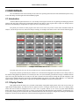
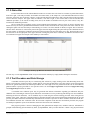
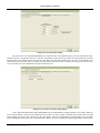
The primary user interface for this program is the main screen. This screen presents various status information about the
analyzer, current and previous tests, and current analyzer readings. An example of the main screen is shown on the following page.
Example AdvancedDAS Main Screen
From this main screen, the user can access all the necessary controls and dialogs to run the emission testing process.
The primary functions performed by this software are 1) the numerical and graphical presentation of live analyzer data, 2)
the numerical and graphical presentation of recent analyzer data , and 3) the automatic generation and storage of standard emission
report files using data obtained from an analyzer. This data is obtained from the analyzer through the personal computer's USB
system using a standard USB cable connected to an ECOM USB-HF radio, directly to a J2KN or EN2 USB port, or to a Bluetooth
adapter. Proper operation of this program, requires that an authorized USBKEY be connected to the host PC.
2.1.1 Display Panels
Data gathered from the analyzer are presented in individually configurable display panels on the main screen, and on an
eight channel trending display. This data may also be captured for use in creating an emission report. There are 12 display panels
on the main screen. These are arranged into two (2) rows of five (5) panels, and one (1) row of two (2) panels. Each individual
display panel may be configured by the user by clicking on the desired panel and making the desired changes. A trend display may
be viewed by clicking the View Trend menu item. Individual channels of the trend may be configured by clicking on the channel's
display box (located at the top and bottom of the trend) and selecting the desired parameters.
26
Copyright Malaquite Corporation 2011. All rights reserved.
AdvancedDAS User Manual
2.1.2 Status Bar
Located at the bottom of the AdvancedDAS window are two status bars. The lower bar contains six panels that indicate,
from left to right, 1) the analyzer model, serial number and comm status, 2) the sample rate, 3) the EXCESS AIR value for boilers
or heaters, 4) the EFF value for boilers or heaters, 5) the total and elapsed recording times, and 6) the time stamp of the last sample
received from the analyzer. The upper status bar indicates, from left to right, 1) the current status of the Pre-Test/Post-Test
calibration procedure, 2) the current recording status, and 3) the number of machines tested as part of the current, if any, PreTest/Post-Test calibration procedure.
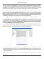
The two status bars are primarily used to present program status information. However, there are areas in the status bars
that the user may click on to get additional information. The first of these click-able areas is first panel of the lower status bar. Left
clicking this panel will cause the Analyzer Status dialog (see section 2.10 of this manual for details) to appear. The second clickable area of the status bars is in the far left panel of the upper status bar. Right-clicking this panel will open the Calibration menu in
the same manner as clicking the Calibration menu item on the menu bar at the top of the main screen. The third click-able area of
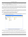
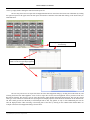
the status bars is the far right panel of the upper status bar. Clicking this panel causes a Summary Of Machines Tested Since PreTest Calibration to appear. An example of this summary is shown below.
Example Summary Of Machines Tested Since Pre-Test Calibration
The user may view the EQUIPMENT folder of any test listed in this summary by simply double-clicking the desired test.
2.1.3 Test Procedure and Data Storage
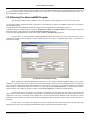
A standard emission report may be created using this software by simply clicking on the Start Recording menu item.
Doing so will cause the program to begin to capture data for one to three measurement cycles after which a report and supporting
data will be generated and stored as common spreadsheet files. The length of the test performed and the rate at which data are
gathered and the report(s) generated are user specified values. See the Configure Application menu item Configure Recording
and Configure Report choices for details.
A somewhat more elaborate report may be generated that includes information regarding pre-calibration and postcalibration tests. Generating an emission report under these circumstances involves performing and entering a Pre-Test calibration.
Following the Pre-Test calibration, 1 to 30 machines may be tested using the normal recording procedure. After testing the last
machine of the group, a Post-Test verification must be performed and the results entered. Information obtained from the pre and
post test procedures will then be automatically included into the emission report files for those machines tested between the PreTest calibration and Post-Test verification. After the successful completion of the Post-Test Verification procedure, the program
will attempt to update the reports for all machines tested since the last Pre-Test Calibration.
This program provides a means of managing the data gathered from multiple sites, machines and tests. Information is
grouped in automatically generated folders by SITE, by EQUIPMENT, and by test date and time. A SITE is any physical location
27
Copyright Malaquite Corporation 2011. All rights reserved.
AdvancedDAS User Manual
with one or more machines or pieces of equipment. For example, a power plant or compressor station are examples of a SITE. A
SITE may have many pieces of EQUIPMENT or it may have only one piece of EQUIPMENT. For example, a lone compressor
that is miles from any other machine would best be considered as a SITE containing one piece of EQUIPMENT. A piece of
EQUIPMENT is any machine which may be monitored by an analyzer. Examples would be an engine driving a compressor or
pump, a turbine driving a generator, a boiler or process heater or any other single piece of emission generating machinery.
Separate folders are automatically generated for each SITE created. Within each SITE folder, separate folders are created
for each piece of EQUIPMENT located at that SITE. Within each EQUIPMENT folder, are stored emission report files generated
for that piece of EQUIPMENT. Emission report files are named by date, time and function. Optionally, emission report file names
may include the associated SITE name, EQUIPMENT name and/or test quarter (ie Q1, Q2, …). Optionally, an analyzer report file
may be generated for each pre/post calibration cycle. If used, these files are stored in the DATA folder under ANALYZERS and
further separated into four folders by analyzer model, AC, APLUS, J2KN, and KL. All of these folders, SITE, EQUIPMENT, and
ANALYZERS, are stored under the DATA folder that is located in the main ECOM_DAS folder.
WARNING! DO NOT ALTER THE CONTENTS OF THE ECOM_DAS, HELP OR DATA FOLDERS
The contents of the ECOM_DAS, DATA and HELP folders must not be altered, renamed, deleted or moved from their
location within these folders. Do not rename these folders or any subfolders. Do not delete, rename or move any of the files
contained withing these folders and their subfolders. These folders and files are expected to be named as they are and located
where they are by the AdvancedDAS program. ALTERING ANY OF THESE FILES CAN RESULT IN THE PERMANENT
LOSS OF RECORDED DATA AND/OR REPORT INFORMATION!
Each time a test is completed, up to six spreadsheet files can be created. Operator controls are provided to indicate which
files are to be created. Each of these files' name begins with the date followed by _ followed by the time followed by _. The next
section of the filename is an user controlled option that may include the site name, the equipment name and the quarter of the year
when the test was conducted. The remainder of the file name is a description of the file contents.
Example Equipment Folder Contents
The spreadsheet files produced are all text files organized with commas separating various information fields and meet the
requirements of a COMMA SEPARATED VALUE (*.csv) file. Note that these files contain only data gathered and results of
calculations performed. These files are easily read by commonly available spreadsheet programs. The six files produced are the
DATA file, REPORT file, the CALCULATIONS file, the SUPPORT file, the CALIBRATION file, and the MASTER file. A brief
description of each file follows:
DATA file:
This file contains basic identifying information about the SITE and EQUIPMENT and the DATA gathered from the analyzer
28
Copyright Malaquite Corporation 2011. All rights reserved.
AdvancedDAS User Manual
during each of the three tests.
REPORT file:
This file contains more detailed information about the SITE and EQUIPMENT and final calculated values of mass emissions.
CALCULATIONS file:
This file contains a simple explanation of how the mass emission values were calculated.
SUPPORT file:
This file contains a simple explanation of how the F Factor used in the mass emission calculation was obtained.
CALIBRATION file:
This file contains the results of the pre and post calibration tests and reports any corrections generated for the measured average
values of CO, NO, NO2, O2. This file is only generated for tests run while in a Pre-Test/Post-Test calibration procedure.
MASTER file:
This file is a single file that may house the contents of any or all of the above files. The contents of this file are user selected.
Additionally, when operating in a Pre-Test/Post-Test calibration procedure, an analyzer report file may be created. This
file will contain a summary of the calibration procedure and a list of machines tested as part of that procedure.
By using this scheme of report file organization, it is possible to easily store, utilize and archive large numbers of
emission reports for a large numbers of machines located at numerous sites. Finding a particular report becomes a simple matter of
opening a selected SITE's folder, opening the appropriate EQUIPMENT folder and selecting the emission report generated on the
desired date and time using 1) the program’s Browse Reports function, 2) the report list box on the Select Site/Equipment dialog,
or 3) by using the standard Windows Explorer. Please note the warning above and do not rename, delete, move or alter any folders
and any file that does not end in .csv!
2.2 Basic Use
The followings provide a brief description of the basic use of the AdvancedDAS program.
2.2.1 Connection/Power Up Sequencing
After an analyzer is setup and functioning on a host PC, there is a recommended practice for connecting an analyzer's
communication link to a PC relative to PC power-up and user login. Failure to follow this practice can result in failure to link to
the target analyzer and a very complex and time consuming resolution procedures.
The recommended practice to connect a target analyzer to a host PC is:
1. Begin with the analyzer's USB-HF radio, direct connect USB port or Bluetooth adapter disconnected from the
host PC. If an external USB hub is used to link the target analyzer to the PC, this external hub must be
disconnected from the host PC. Note that if an external USB hub is used to link the target analyzer to the host
PC, the USB-HF radio, direct connect USB port or Bluetooth adapter may remain connected to this external
hub.
2. Turn the host PC ON, and login to the operating system under the normal user account.
3. Turn the target analyzer ON.
4. Connect the target analyzer's USB-HF radio, direct connect USB port or Bluetooth adapter to the host PC. If an
external USB hub is used to link the target analyzer to the host PC, connect this external hub to the PC. Note
that if a Bluetooth adapter is being used, it must be plugged into the same USB port as was used when the
Bluetooth link was first setup. Also, if a Bluetooth adapter is being used to link the target analyzer to the host
PC via an external USB hub, the external USB hub must be plugged into the same USB port that was used
when the Bluetooth link was first setup and the Bluetooth adapter must be plugged into the same port on the
external USB hub as was used when the Bluetooth link was first setup.
29
Copyright Malaquite Corporation 2011. All rights reserved.
AdvancedDAS User Manual
The user is strongly urged to mark the USB port used by the Bluetooth adapter and/or external hub and always follow this
procedure at startup. Failure to follow this procedure can, in some cases, result a failed communication link that can be very
difficult and time consuming to resolve.
2.2.2 Running The AdvancedDAS Program
After the AdvancedDAS software and drivers have been loaded, use of this program involves only a few basic steps.
1) Connect the analyzer communication link to the host PC as described above, connect the USBKEY to the host PC, and start the
AdvancedDAS program.
2) Setup the SITE and EQUIPMENT information using the Select Site/Equip choice under the File menu item.
3) Setup the desired recording parameters using the Configure Recording, and Configure Report and specifying the technician's
name and company name using choices under the Configure Application menu item.
4) Select the Site and Equipment to test and start a test by clicking the Start Recording menu item.
For step 2 above, an example SELECT SITE/EQUIPMENT dialog is shown below. This is the dialog that is used to create
new sites and/or equipment in the database, to edit information about a site or piece of equipment and to select a site and piece of
equipment for testing.
Example Select Site/Equipment Dialog
When entering the SITE and EQUIPMENT information on the SELECT SITE/EQUIPMENT dialog, enter as much
information as possible. Note, however, that only the permit limit settings, found on the Permit Information tab, are required for
proper operation of the program. When choosing names for a site or piece of equipment, use only letters and numerals to form the
name. Do not use symbols such as decimal or comma. For example the site name Power Station No. 2 is incorrect as it contains a
decimal character. An example of a proper site name would be Power Station No 2 without the decimal character.
After entering, editing, or selecting a Site and piece of Equipment, the user must close this dialog by clicking the OK
button at the lower left corner of the dialog. It is important to note that the Site and Equipment shown selected (Selected items are
displayed in reverse text in a blue bar. In the example above, Generic Site and Generic Machine are the selected items.) in this
dialog when the OK button is clicked becomes the Site and Equipment that the program assumes will be tested in the next test
procedure.
For step 3 above, an example of the dialog used to enter the technician's name and company name is shown below. This
dialog allows the user to enter identifying information that will be repeated on the final emission report.
30
Copyright Malaquite Corporation 2011. All rights reserved.
AdvancedDAS User Manual
Example Technician Name Entry Dialog
Also for step 3 above, an example of the dialog used to configure the recording parameters is shown on the following
page. This dialog allows the user to specify how the program is to conduct the actual emission test. Included on this dialog are
specifications for sample rate, measure cycle duration, measurement cycle count, and ramp-up and purge.
Example Configure Recording Dialog
When setting up the recording parameters, note that the program will alter the RAMP-UP TIME, TEST DATA TIME, and
PURGE TIME entered as necessary to be sure the value is an integer number of sample periods. For consistency sake, the program
will always round up.
For reporting protocols that require a ramp-up cycle before the test phase or a purge cycle after the test phase, the program
provides a means of inserting either or both procedures between each of the test cycles. See the Configure Recording choice under
the Configure Application menu item.
After these basic values have been entered, operation of the program simply involves monitoring the values measured by
the analyzer by viewing the display panels on the main screen or by viewing selected analyzer parameters on the trend display and
initiating an emission report by clicking the Start Recording menu item when ready.
For step 3 above, an example of the Configure Report dialog is shown below.
31
Copyright Malaquite Corporation 2011. All rights reserved.
AdvancedDAS User Manual
Example Configure Reports Dialog
This dialog allows the user to specify what report files to generate as the result of each test procedure.
2.2.3 Creating An Emission Report
Creating an emission report is a straightforward procedure. The user selected emission report(s) are automatically
generated and stored after the end of the test. With the equipment all connected, powered ON and running, the user may observe
the measured values from the analyzer on the display panels of the main screen or on the trend display. New data values from the
analyzer will be updated on the main display and trend once every second. The running averages displayed on the main screen may
be individually reset by clicking the AVERAGE button in the desired display panel or by clicking the Reset All Averages menu
item.
When ready, the user may initiate the generation of a simple emission report by clicking the Start Recording menu item.
The program will respond by gathering some additional information, user comments and starting sensor temperature, and begin the
first measurement cycle. Each measurement cycle is user configured using the CONFIGURE RECORDING dialog shown on the
previous page. A measurement cycle will always include a TEST DATA phase in which samples values from the analyzer are
stored for later reporting. A measurement cycle may also include RAMP-UP and PURGE phases. The RAMP-UP phase is a period
of time immediately proceeding the TEST DATA phase during which the analyzer is first connected to an emission source and
begins drawing sample gas into the instrument for analysis. During the RAMP-UP phase, the measured values of the various gas
components normally begin to increase from 0, to ramp-up, as the new sample is drawn into the analyzer. The PURGE phase is a
period of time immediately following the TEST DATA phase during which the analyzer inlet is disconnected from the emission
source and the instrument is allowed to draw in fresh air to purge its electrochemical cells. Using the dialog shown on the previous
page, the user may elect to include or not include each of these phases and to record or not record data during these phases.
After completing the required number of measurement cycles, the program will automatically stop and again give the user
an opportunity to enter any comments and to enter the ending sensor temperature. The program will then calculate the mass
emission rates for the tests completed and will generate the requested spreadsheet files.
The user may choose to manually stop the recording process by clicking the Stop Recording menu item. This is not a
recommended procedure as doing so will prevent the proper number of samples from being captured and will interfere with the
proper reporting of the emission test.
2.2.4 Operator Comments
The user is given a chance to enter any comments desired both at the beginning and end of the test. This is a convenience
function serving two purposes. 1) the dialog box requesting the user's comments is a visual reminder of the beginning and end of a
test, and 2) any comments entered become the Notes part of the DATA file and eliminate the need to make, track, and file paper
notes. An example of the operator comments dialog is shown below.
32
Copyright Malaquite Corporation 2011. All rights reserved.
AdvancedDAS User Manual
Example Operator Comments Dialog
2.2.5 Sensor Temperature
The AdvancedDAS program records the analyzer sensor temperature at the beginning and end of each test. Both
temperature values recorded as well as a calculated average temperature are reported in both the DATA and REPORT reports. The
sensor temperature values are only reported in the program's output and is not used in any internal calculations.
Examples of the Sensor Temperature dialog for the start and end of test are shown below. As large differences in sensor
temperature between pre-test and test and between start of test and end of test, and between pre-test and post-test can contribute to
gas concentration reading errors and, in some cases, post-test failure, the Sensor Temperature dialog presents not only the current
sensor temperature, but compares this value to the pre-test sensor temperature and displays a differential value for the user.
Exceptionally large differences result in an additional warning message on this dialog.
Example Start Of Test Sensor Temperature Dialog
The Sensor temperature dialog shown at the end of the test also shows a comparison of the start and end sensor
temperatures.
33
Copyright Malaquite Corporation 2011. All rights reserved.
AdvancedDAS User Manual
Example Start Of Test Sensor Temperature Dialog
Both of these displays are presented for the user's benefit with the intention of helping the user monitor the change in the sensor
temperature.
2.2.6 Pre-Test Calibration / Post-Test Verification Procedure
The program is capable of capturing pre and post test calibration data and applying this data as corrections to measured
values contained in test reports generated between the Pre-Test and Post-Test calibrations. When using this capability, the user may
test up to 30 machines between the Pre-Test and Post-Test procedures.
The ability to gather and apply Pre-Test and Post-Test calibration information may be enabled or disabled by the user
using the Perform Pre And Post Calibration Procedures check item in the Configure Application menu item. Checking and
unchecking this item enables and disables this function and shows or hides the Calibration menu item. Note that once a PreTest/Post-Test calibration procedure is begun, the function may not be disabled until the current procedure is completed or aborted
by the user.
AdvancedDAS handles the Pre-Test/Post-Test process by providing data entry screens for the user to capture test results.
Pre-test and Post-Test readings from the analyzer are captured or entered by the user on this screen. An option also exists to cause
the program to capture a recording of both the Pre-Test Calibration and Post-Test Verification procedures and to append this
recording to the end of the calibration report. Prior to starting a Pre-Test/Post-Test sequence, the user should enter all the
appropriate values in the MEASUREMENT SYSTEM, PRE-TEST AND PORT-TEST RECORDING, and CAL GAS
INFORMATION tabs of the calibration dialog. A typical Pre-Test data entry dialog is shown on the following page.
34
Copyright Malaquite Corporation 2011. All rights reserved.
AdvancedDAS User Manual
Example Pre-Test Dialog
Related dialogs are used for entry of Measurement System, Pre-Test and Post-Test Recording, and Cal Gas Info as well as entry of
Pre-Test and Post-Test data. Note that different tabs and areas of this dialog are enabled or disabled for editing depending upon
what function is currently being performed. These dialogs may be accessed by either clicking on the Calibration menu item on the
main menu, or by right clicking the far left panel of the upper status bar located at the bottom of the main screen.
The basic steps required for using this procedure are:
1) Enable the Perform Pre And Post Calibration Procedures check item in the Configure Application menu..
2) Enter the Measurement System and Calibration Gas Information by clicking the Calibration menu item and selecting the Enter
Cal Gas Info item. Fill in the Measurement System, Pre-Test and Post-test Recording, and Cal Gas Information tabs of the dialog.
If the Pre-Test and Post-Test procedures are to be recorded, the Record Pre and Post test Data checkbox should be checked and the
Sample Rate should be set to 1 Second/Sample. Note that for any calibration gas that is not to be used, for example NO2, a SPAN
value of 100 must be entered. Do not simply enter the value 0 for the CAL GAS SPAN value as this will result in numerous errors
and the loss of test data.
IMPORTANT!
Note that for any calibration gas that is not to be used, for example NO2, a CAL GAS SPAN value of
100, a RESPONSE value of 100 and a ZERO value of 0 must be entered for the gas component that is
not used. Do not simply enter the value 0 for these values as this will result in numerous errors and
the loss of test data.
THIS IS VERY IMPORTANT. Be sure that all values in the Measurement System and Cal Gas Info sections are entered
completely and correctly before starting a Pre-Test. Once the Pre-Test is started, it will become impossible to edit the Measurement
System and Cal Gas Info values. Be very aware of this requirement especially after changing a calibration gas bottle or calibration
gas concentration.
READ THE ABOVE PARAGRAPH ONCE AGAIN!
3) Perform the normal Pre-Test calibration procedure. Enter or capture the information obtained into this program by clicking the
Calibration menu item and selecting the Pre Test Calibration item. See the associated help for details on each of these values.
Starting with version 1.6.6.19, new columns of buttons labeled Capture Zero and Capture Response have been added to this dialog.
35
Copyright Malaquite Corporation 2011. All rights reserved.
AdvancedDAS User Manual
These buttons are located in the PRE-TEST DATA and POST_TEST DATA tabs of the dialog. Clicking one these buttons causes
the corresponding current value from the analyzer to be copied into the appropriate ZERO or RESPONSE edit box and a
corresponding note to be added to the Pre-Test or Post-Test recording.
Ex.
Click this button to copy the current
value of CO into the CO ZERO edit
box.
Example Capture Analyzer Values Dialog
Use of the CAPTURE ZERO and CAPTURE RESPONSE buttons is recommend but not required. The user may either read the
values from the analyzer hand-held remote and type them in manually, or click the appropriate CAPTURE button to capture
analyzer readings automatically.
Also new starting in 1.6.6.19 is a column of buttons labeled Cal CO, Cal NO, and Cal NO2. These buttons may be used to
automate the calibration sequence for CO, NO, and NO2. These buttons work by eliminating the need for the user to have to place
the analyzer in Control mode, swipe a magnet, select a gas to calibrate, enter the calibration value, and return the analyzer to
normal mode. Normal use of one of these buttons requires that the Cal Gas information is entered correctly and matches the
readings on the cal gas bottles used to calibrate the analyzer. Afterward, the user connects a calibration gas to the analyzer and
starts the Pre-Test Calibration process in this program. After the analyzer's reading for the selected gas has stabilized, the user
simply clicks the Cal button corresponding to the calibration gas currently connected to the analyzer. The program will
automatically calibrate the analyzer and capture the analyzer's response after the calibration is complete. The automatic calibration
process takes seconds to complete.
After completing the Pre-Test calibration and entering and checking all the requested data, click the PRE-TEST
COMPLETE button to store this information and ready the program to begin testing equipment. As the typical Pre-Test procedure
has many steps and takes some time, the user may wish to temporarily close the data entry dialog in order to attend to other tasks.
This may be accomplished by clicking the OK button. When the OK button is clicked, any data values that have been entered are
stored, but the Pre-Test procedure is not completed. The user is then free to return to this dialog later to enter more calibration test
results or to declare the procedure complete or to abort the procedure. After all the Pre-Test data have been gathered, entered, and
checked, the user should click the PRE-TEST COMPLETE. This will signal the end of the Pre-Test process and enable the
machine testing portion of the Pre-Test/Post-Test sequence.
4) Perform normal machine emission tests by first selecting the appropriate SITE and EQUIPMENT and clicking the START
RECORDING menu item. From 1 to 30 machines may be tested.
IMPORTANT!
Do not delete any test results files prior to completing the Post-Test Verification procedure.
36
Copyright Malaquite Corporation 2011. All rights reserved.
AdvancedDAS User Manual
5) After all the desired machines have been tested, perform the normal Post-Test verification check. Enter the Post-Test
information by clicking the Post Test Calibration item in the Calibration menu. After the necessary information has been entered
and checked, click the POST_TEST COMPLETE button to save this information, update emission reports on all the machines
tested since the Pre-Test procedure and to generate an analyzer report, if desired.
Because it is reasonable to expect that machine testing will take place over an extended period of time and that this
program and the associated PC may be stopped when moving from machine to machine, visual indication of the status of the
procedure is provided on the status bars located at the bottom of the AdvancedDAS window. The left most panel of the upper
status bar will indicate the current status of the Pre-Test/Post-Test calibration procedure, the middle panel of the upper status bar
will indicate the status of the current test, and the right most panel of the upper status bar will indicate the number of machines
which have been tested under the current Pre-Test/Post-Test calibration procedure.
Note that once a Pre-Test/Post-Test calibration procedure is begun it must be completed normally in order for calibration
data to be applied to machine emission reports. This procedure may be terminated manually by the user by clicking the Abort
Calibration item in the Calibration menu. However, doing so will destroy any Pre-Test data entered and will prevent any
subsequent machine emission test reports from being updated with calibration information.
2.2.7 Locating And Reviewing An Emission Report
Report files generated by the AdvancedDAS program are stored in folders located in the Data folder. Convenient access to
these folders is provided by Browse Reports item located in the File menu. Clicking the Browse Reports item opens an Explorer
window for the Data folder similar to the example shown below.
Example Data Folder Contents Viewed With Browse Reports
The Data folder will always contain folders named Analyzers, Compositions, and Trash as well as one folder for each Site that has
been created in the AdvancedDAS database. In the example above, there is only one Site. This Site is named Generic Site.
In order to access emission report files for prior tests, the user should locate the folder for the desired Site using the
Browse Reports item and double click the desired Site folder to open it. Within the opened Site folder will be a folder for each
piece of equipment located at that Site. Locate the folder for the desired piece of equipment and double click that folder to open it.
A listing of emission report files for that piece of equipment will then be displayed. The user may then select the desired report and
37
Copyright Malaquite Corporation 2011. All rights reserved.
AdvancedDAS User Manual
view it by simply double clicking the desired emission report file.
The user may also access test report files for Equipment that has been tested since the last Pre-Test Calibration by clicking
the right most panel of the upper status bar that reports the number of machines tested and then clicking on the desired entry as
illustrated below.
Click this panel to open the View Machines
Tested dialog.
Click an entry in this list to open an explorer
window to the corresponding Equipment
folder.
The user may also access test report files from the Select Site/Equipment dialog by clicking the Test Records tab, and
selecting the desired Site and Equipment. A list of all test report files for the selected Equipment will be presented on the Test
Records tab of dialog. The user may view any report file listed by simply double-clicking the desired report. The user may control
what type of test records are listed in this box by using the File Display Options control located at the bottom of the Test Records
tab. This control gives the user the ability to show both pdf and csv files, only pdf file, or only csv files. Additionally, the user can
alter the displayed order either increasing or decreasing date of the files by clicking on the column header labeled Date. An
example of the Select Site/Equipment dialog is shown below.
38
Copyright Malaquite Corporation 2011. All rights reserved.
AdvancedDAS User Manual
Double-click any of the report files listed to
view the report.
Example Select Site/Equipment Dialog
2.2.8 Database Backup
The contents of the AdvancedDAS database should be backed up often to avoid data loss in the event of a computer or
hard drive failure. The program was designed with this in mind and performing a backup is as simple as copying the entire
ECOM_DAS folder to a backup drive or device. Doing so will preserve the AdvancedDAS program, all user settings, and all site
and equipment settings and emission reports.
Note that while the AdvancedDAS program must not be installed on a USB FLASH drive or run from a USB FLASH
drive, using a USB FLASH drive as a backup drive to store a copy of the ECOM_DAS folder is perfectly fine. However, the
USBKEY should not be used for this purpose.
2.2.9 Communicating With The J2KN Analyzer Using The USB-HF Radio
Electronically gathering data from the J2K(N) analyzer involves the use of a radio, USB connection, or Bluetooth to the
target PC to receive data from the analyzer. The radio device is the USB-HF radio which is a special USB linked 900MHz radio
transceiver. A photograph of a USB-HF radio is shown below.
USB-HF Radio Photograph
Each USB-HF radio is specially programmed to work with its matching analyzer and will only work with the J2K(N)
analyzer whose serial number matches the radio's serial number and operating channel. All USBHF radios and J2KN analyzers
39
Copyright Malaquite Corporation 2011. All rights reserved.
AdvancedDAS User Manual
default to operate on channel 5. When using the AdvancedDAS program with a J2KN analyzer, the radio channel being used by
the USBHF radio is shown in the panel at the left end of the lower status bar. The channel number used by the analyzer is shown
on the hand-held remote on the lower right corner of the CONTROL screen.
Since the USB-HF radio is a 900MHz device, it needs to have a clear path between it the J2K(N)analyzer, and the handheld remote for good signal reception. Also, the radio should not be placed horizontally on a metal table or metal floor. Best
performance will be achieved when the USB-HF radio is held perpendicular to a metal surface. For that reason, the USB-HF radio
is equipped with a clip and soft feet to allow it to easily be oriented in a vertical position while being clipped on the open lid of a
laptop computer.
When not in use, the USB-HF radio and its USB cable should be stored in the case of the matching J2K(N)analyzer. A
clear plastic tube with easily removed end caps is provided for this purpose. Note that the USB cable must be removed from the
USB-HF radio before storing the USB-HF radio in the plastic tube to avoid accidental damage to the USB connector. The user is
strongly urged to store the USB-HF radio in this manner to assure that the radio will always be available in the field for use. This is
contrasted to the situation in which the radio is stored in a laptop travel case that may be replaced or lost or transferred to different
personnel or confused with the USB-HF radio matched to a different J2K(N)analyzer. Obviously, any of those situations would
result in the user's inability to conduct an emission test. The user should keep in mind that the data link for the AdvancedDAS
program is a radio link and even though extensive error checking is employed in the data link, a radio link is subject to interruption
and interference. Such interference and interruption is beyond the control of the manufacturers and is the responsibility of the user
to watch for and manage.
The recommended procedure to minimize the potential for data link interference or interruption is to choose the location
of the J2K(N)analyzer and the USB-HF radio carefully. Avoid locations that place metal obstructions in the line of sight between
the analyzer, the hand-held remote, and the radio. Limit the distance between the analyzer, the hand-held remote, and the radio to a
minimum. The user may take advantage of the signal strength and link quality indicators located in the lower right corner of the
AdvancedDAS main screen to access the suitability of a particular set of locations.
Link Quality Indicator Location
The indicators consists of two vertical bar displays labeled B and R, and one round display above the two bars. Note that
the bar indicators are only presented when the user is connected to a J2KN analyzer using the enhanced protocol. When connected
to an EN2 analyzer, only the round Link Quality display is shown. The bar labeled R provides a relative signal strength for the
radio signal received by the USB-HF radio from the hand-held remote. The bar labeled B provides a relative signal strength for the
radio signal received by the USB-HF radio from the analyzer base unit. Both of these bars are color coded either green, yellow, or
red. Green indicates a suitably strong signal. Yellow indicates a low signal level. Red indicates a weak signal level. The complete
absence of a radio signal is indicated by the entire bar being filled with a red cross-hatch pattern. The communication exchanges
that take place between the various radio devices are complex, and although a strong signal is important, it is not a complete
indication of the ability of the USB-HF radio, the hand-held remote and the analyzer base unit to communicate with one another. A
more accurate predictor of the radio link quality is provided by the round indicator located at the right side of the
COMMUNICATIONS LINK INFORMATION box. This indicator is also color coded green, yellow, and red to indicate good link
quality, low link quality, or poor link quality. For the J2KN analyzer, the USB-HF radio, the hand-held remote, and the analyzer
base unit should be arranged to yield the strongest possible signal strengths and the highest link quality. However, even in
40
Copyright Malaquite Corporation 2011. All rights reserved.
AdvancedDAS v1663 100107
AdvancedDAS User Manual
situations where good signal strength and link quality are initially obtained, changes beyond the user's control can cause the link to
suddenly become very poor and result in the loss of data or the loss of control of the analyzer.
The USB-HF radio is a high quality device and is designed to resist outside radio interference. However, very high power
signals on nearby frequencies and/or operation of other radio devices that are malfunctioning can interfere with the data link to the
analyzer. If that happens, the AdvancedDAS program can temporarily lose data or lose control of the analyzer. The user should
make every effort to determine what radio equipment is in use in the vicinity of the J2K(N)/USB-HF radio pair and silence any
suspect equipment for the duration of the emission test in order to avoid data loss during a test as well as choose a physical
location that minimizes the chance for a large object such as a vehicle from moving through the radio signal path.
Having taken the steps described above, a suitable location should be found and when ready, emission testing can begin.
In the event that radio interference or interruption occurs while the AdvancedDAS program is monitoring a J2K(N)analyzer, one of
several events can occur. The radio signal will be weakened or interfered with such that reliable data extraction becomes
impossible from either the hand-held remote, the analyzer base unit or both. When any of these conditions occurs, an informative
pop-up will appear on the target PC.
2.2.10 Communicating With The J2KN or EN2 Analyzer Using USB or Bluetooth
A suitably equipped J2KN or EN2 analyzer may be linked to the host PC and AdvancedDAS program via either a USB
link connected to the analyzer's USB port or a Bluetooth radio link. Note that the user must choose one or the other of these two
links as using both at the same time will result in the failure of both communications links.
IMPORTANT: The user must choose either the analyzer's USB port or the Bluetooth
radio port. Attempting to use both at the same time will result in the failure of both
communications links. As such, it is recommended that the USB Bluetooth radio not be
plugged into the host PC any time the analyzer USB port is being used.
If the user chooses to utilize a Bluetooth link, a suitable Bluetooth device for the host PC must be acquired, installed, and
configured. See section 1.3 for details. Regardless of which link is chosen, the user should be sure that analyzer is ON and the
chosen link is connected or established before starting the AdvancedDAS program. When communicating with the analyzer, Link
Quality Indicators and warnings similar to those issued for the USB-HF radio will be presented on the main screen of the
AdvancedDAS program. When using the EN2 with a direct USB link, the Signal Quality Indication will be of little value as this
link will function perfectly or not at all. When using a Bluetooth link, the Signal Quality Indicator will change color Green/Yellow/
Red to indicate diminishing link quality, but more importantly, the round Signal Quality Indicator on the main screen of the
AdvancedDAS program will flash to indicate that the link is failing. Any time that this flashing is observed, the user should take
steps to improve the radio link between the analyzer and the host PC by removing obstacles between the two devices or by moving
the two devices closer together.
2.3 Site/Equipment Database
After using this program for a very short period of time, the typical user will generate a very large number of report files.
Without an organized storage method, these files would become difficult to locate for future reference. AdvancedDAS avoids this
problem by organizing information and reports into groups. The primary group used is the SITE. For AdvancedDAS, a SITE is any
separate physical location that has one or more emission producing machines. A SITE may have one machine, such as a lone
compressor in a pasture, or it may contain several machines, such as a power plant that has 5 diesel powered generators.
AdvancedDAS will automatically create a folder for each SITE created by the user. This SITE folder will be given the name of the
SITE and will be stored in the DATA folder.
AdvancedDAS further organizes information by using a secondary group under the SITE group that is referred to as
EQUIPMENT or EQUIP for short. For AdvancedDAS, a piece of EQUIP is any single emission producing machine such as an
engine, turbine, or boiler. AdvancedDAS will automatically produce one folder for each piece of EQUIP created by the user and
will name the folder with the name of the piece of EQUIP. Each EQUIP folder is stored within its associated SITE folder. This is
done automatically by AdvancedDAS.
The next lower level of organization implemented by AdvancedDAS is to store setup information and report files for a
given piece of EQUIP in the machine's EQUIP folder. Within each EQUIP folder, will be every report created for that machine.
The final level of organization implemented by AdvancedDAS is to give each report file a filename that begins with the date the
associated test was run, followed by the time of the test. When viewed using the Browse Report function or the Windows Explorer,
41
Copyright Malaquite Corporation 2011. All rights reserved.
AdvancedDAS User Manual
the files contained in a machine's EQUIP folder will automatically be sorted by the reports' test dates and thus will be easy to
locate.
For further convenience, the user may choose to have AdvancedDAS add the SITE name, EQUIP name, and quarter of the
year to each report's filename. This is redundant information when the report files are stored in the AdvancedDAS database.
However, as the report files are moved off the report generating PC to possibly a central computer for archiving, having the SITE,
EQUIP and quarter information in the report filename can help avoid confusion.
The process of creating and arranging all these various folders is handled by the AdvancedDAS program using the
SELECT SITE/EQUIPMENT dialog. An example of this dialog is shown below.
Example Select Site/Equipment Dialog
This dialog consists of two major sections, the SITE section and the EQUIPMENT section. The SITE section contains a
list of all sites that have been setup in the database, and AREA and FACILITY names for the slelcted site entry. The EQUIPMENT
section contains a list of all the equipment that has been setup in the database for the selected site as well as tab divided pages
containing EQUIPMENT INFORMATION, PERMIT INFORMATION, and TEST RECORDS for the selected equipment.
The user must use this dialog to create new SITEs and new pieces of EQUIP in the database, to enter or edit details about
each SITE or piece of EQUIP, and, when performing an emissions test, to select the target SITE and piece of EQUIP to be tested.
In addition to storing emission reports generated for each piece of EQUIP, the AdvancedDAS database also stores details
about each SITE and piece of EQUIP for use in creating new reports. For each SITE, the database stores a list of machines at that
site, and descriptions of the area and facility. Typically, the facility description is set equal to the SITE name.
Substantially more information is stored for each piece of EQUIP in the AdvancedDAS database. This information
consists of text data used to fill out report forms. In order to use this information, the AdvancedDAS program requires the user to
use the Select Site/Equip dialog to select or indicate which SITE and piece of EQUIP is being monitored so that the appropriate
settings can be retrieved. Thus before starting work on a given machine, the user should first go to the Select Site/Equip dialog and
select the machine to be monitored or if the machine is not in the database, enter it into the database. After selecting the SITE and
EQUIP to work with, the user may close the Select Site/Equip dialog. At this point, the software will provide a visual reminder of
the SITE and EQUIP selected by displaying this information at the top of the main window.
42
Copyright Malaquite Corporation 2011. All rights reserved.
AdvancedDAS User Manual
2.3.1 Creating A New Site
When the AdvancedDAS software is run for the first time, it will automatically generate a Generic Site and a Generic
Machine for that site. This is done for convenience to allow the user to immediately begin using the software.
When the user is ready to begin doing real monitoring and reporting, it will be necessary to create database entries for the
SITEs and pieces of EQUIP that are to be tested. The process of creating a new SITE simply involves right-clicking the Sites In
This Database list box, entering a name for the new site and clicking OK. A new SITE folder will automatically be created within
the DATA folder and the database's SiteList will be updated to include the new SITE. On the Select Site/Equip dialog, the SITE's
Facility field will automatically be filled in with the SITE name. The user should then enter a suitable description for the Area
field. This completes the basic requirements to create a new SITE.
In general, the user may enter any name for a site. However, because the site name entered also becomes the name of the
site folder, there are some limitations on the characters used in the new site name. These limitations are the result of limits imposed
by the Windows operating system. Site names and Equipment names also should only consist of letters, numerals, and space
characters. Any other characters are not allowed and if entered will result in the error message shown below.
Invalid Site or Equipment Name Error Dialog
Because the AdvancedDAS software is focused on monitoring individual machines, having a SITE with no EQUIP is not
allowed. Upon initially creating a new SITE, the EQUIP selector will display “NO EQUIP SETUP FOR THIS SITE”. This is a
reminder to the user to then create a piece of EQUIP for this new SITE. If the user should choose to exit the Select Site/Equip
dialog without creating the new EQUIP, the program will issue a warning to either create a new piece of EQUIP or have a Generic
piece of EQUIP automatically created. It is strongly recommended that the equipment associated with the new SITE be entered
when the new SITE is created to avoid possible confusion in the future.
2.3.2 Creating A New Piece Of Equipment
Creating a new piece of EQUIP is somewhat more involved that creating a new SITE as many more pieces of information
need to be entered.
Begin creating a new piece of EQUIP by first selecting the SITE where the machine is located. If the SITE does not yet
exist, the SITE must be created as described above before you may proceed here.
Please take special note, YOU MUST SELECT THE SITE FOR A NEW PIECE OF EQUIP BEFORE CREATING THE
NEW EQUIPMENT! The SITE that is selected when the new equipment is created is the SITE that the EQUIP data will be stored
under.
Having selected the SITE for the new piece of EQUIP, right-click the Equipment Located At This Site list box, enter a
name for the new machine and click OK. The EQUIP's Equipment Name will automatically be filled in with the EQUIP name. Fill
in as much of the remaining information on the dialog as possible. With the exception of the permit CO and NOx limits, the
information on this dialog is stored in the AdvancedDAS database for later use in generating meaningful and informative reports.
The permit limits entered are reported on the output reports. However, the permit limits are also shown on the main window of
AdvancedDAS and compared to the measured emission levels during a test.
After creating the new EQUIP and/or new SITE, save the information entered by clicking the OK button on the Select
Site/Equip dialog.
43
Copyright Malaquite Corporation 2011. All rights reserved.
AdvancedDAS User Manual
2.3.3 Selecting An Existing Site Or Piece Of Equipment
Normal operation of the AdvancedDAS software will typically involve selecting the SITE at which testing will occur and
then selecting the EQUIPMENT to be tested.
The user may make these selections by opening the Select Site/Equip dialog. First the user should click on the desired Site
in the Sites In This Database list box. Doing so will cause the Area and Facility information for that SITE to appear and will cause
the Equipment Located At This Site to be loaded with a list of equipment that have been setup for the selected SITE. The user may
then select the desired machine by clicking on the desired equipment entry. Doing so will cause all the information about that
machine to be filled in..
2.4 Recording Configuration Settings
Use the CONFIGURE RECORDING dialog to specify how the analyzer data is to be recorded.
Opening Splash Screen
A recording of emission data will consist of one, two, or three measurement cycles. These measurement cycles are of
equal length. The total time for each of the measurement cycles is specified in the TOTAL CYCLE DURATION box. This value is
the sum of the RAMP_UP TIME, the TEST DATA TIME, and the PURGE TIME. If the item, No Ramp-Up Before Each Cycle is
selected, the RAMP-UP TIME is not included in the TOTAL CYCLE DURATION. If the item, No Purge After Each Cycle is
selected, the PURGE TIME is not included in the TOTAL CYCLE DURATION.
When entering a value for either the RAMP-UP TIME, TEST DATA TIME, or PURGE TIME, enter a time value in the
form of hours:minutes:seconds (example 03:35:45). Note that minimum and maximum values for each of these parameters is
00:00:03 and 03:00:00, respectively. The program will verify the value entered and may alter the value slightly to produce a time
that corresponds to an integer number of samples at the RECORDING SAMPLE RATE specified.
The user may choose to include a Manual or Automatic Ramp-Up Before Each Cycle and/or a Manual or Automatic
Purge After Each Cycle. Note that only the J2KN Industrial analyzer is capable of performing automatic Ramp-Up and Purge
functions. If either of these manual options are chosen, the program will present a pop-up window informing the user to take the
manual action requested during each test cycle. For example, if the user chooses to include a manual Ramp-Up at the beginning of
each measurement cycle, the program will generate the pop-up shown below at the beginning of each measurement cycle. The user
is then expected to click the Close button after the analyzer inlet has been connected to the exhaust stream being tested.
44
Copyright Malaquite Corporation 2011. All rights reserved.
AdvancedDAS User Manual
Example Manual Connect Pop-Up for Manual Ramp-Up
A similar pop-up will be generated at the end of the Test Data phase of each measurement cycle if the user has selected
the Manual Purge After Each Cycle item.
IMPORTANT!
Only the J2KN Industrial analyzer can perform automatic Ramp-Up and Purge operations. When using this
program with a standard J2KN or with the EN2, the automatic selections for Ramp-Up and Purge are disabled.
The ramp-up phase of the measurement cycle may be included in the data recording if the manual or automatic ramp-up
has been selected and the Record Ramp-Up item is checked. Similarly, the purge phase of the measurement cycle may be included
in the data recording if the manual or automatic purge has been selected and the Record Purge item is checked.
The user may specify the number of measurement cycles that are to make up a complete test. The available choices are 1,
2 or 3 measurement cycles.
Emission data will be gathered from the analyzer at the rate specified in the RECORDING SAMPLE RATE box. The
minimum and maximum values for this parameter are 1 and 60 seconds per sample, respectively. Note that after changing the
RECORDING SAMPLE RATE, the RAMP-UP TIME, TEST DATA TIME, and PURGE TIME values may be changed by the
program to produce test recordings of an exact number of samples.
If the user chooses, the program can be made to display an informative pop-up each time the test procedure proceeds from
one state to another. For example, when a measurement cycle end. The Annunciate Change Of State checkbox at the bottom of the
dialog is used for this purpose.
For the J2K(N)analyzer, the user has the option to specify what action is to be taken after the completion of a test
procedure. These options are listed in the POST TEST ANALYZER CONTROL section of this dialog. The four choices are
described below:
●
●
●
●
Return To Sample Mode After Test – This choice will cause the analyzer to return to sample mode after the test is
complete. If the user has chosen to include a purge in each measurement cycle, the analyzer will be in purge mode at the
completion of the test. In that case, with this option, the analyzer will be returned to sample mode after the last cycle has
completed it purge time. In the case where the user has not included a purge in each measurement cycle, choosing this
option will have not effect at the ed of a test as the analyzer will already be in the sample mode.
Purge Analyzer Indefinitely After Test – This choice will cause the analyzer to enter and remain in the purge mode
after the test is complete. If the user has chosen to include a purge in each measurement cycle, the analyzer will be in
purge mode at the completion of the test. In that case, with this option, the analyzer will remain in purge mode after the
last cycle has completed it purge time. In the case where the user has not included a purge in each measurement cycle,
with this option, the analyzer will be placed in purge mode after the last cycle has been completed. The analyzer will
remain in purge mode until it is turned OFF or the user causes a manual exit of the purge mode by clicking the Analyzer
Control menu item and choosing Exit Purge.
Timed Purge And Standby After Test – This choice operates exactly as the Purge Analyzer Indefinitely After Test with
the exception that the user can specify a time in which the analyzer will remain in purge. After that period of time has
expired, the analyzer will be placed in standby mode. Once in standby mode, the analyzer will remain in standby mode
until it is turned OFF or the user causes a manual exit of the standby mode by clicking the Analyzer Control menu item
and choosing Exit Standby.
Do Not Change Analyzer Op State After Test – This choice will result in no change of the analyzer's operating mode
45
Copyright Malaquite Corporation 2011. All rights reserved.
AdvancedDAS User Manual
after the completion of a test. If the user has chosen to include a purge in each measurement cycle, the analyzer will be in
purge mode at the end of a test and will remain so if this option is chosen. In the case, the analyzer will remain in purge
mode until it is turned OFF or the user causes a manual exit of the purge mode by clicking the Analyzer Control menu
item and choosing Exit Purge. Alternately, if the user has chosen not to include a purge in each measurement cycle, the
analyzer will be in sample mode at the end of a test and will remain in sample mode.
If the user chooses, the program can be made to display an informative pop-up each time the test procedure proceeds from
one state to another. For example, when a measurement cycle end. The Annunciate Change Of State checkbox at the bottom of the
dialog is used for this purpose.
2.5 Report Configuration Settings
The Recording Output dialog is provided to allow the user to control the reports generated by the AdvancedDAS program
and the report filename structure. An example of this dialog is shown below.
Example Recording Output Control Dialog
Using the checkboxes at the top of this dialog, the user may add other information to the program's output report
filenames. In addition to the standard date_time_name.csv report filename, the SITE name, EQUIP name and quarter of the year
may be added to each report's filename. Each of these items may be added individually or they all may be added. By clicking the
appropriate checkbox, the user may cause the report filename to include
the SITE name as in date_time_SITE_name.csv
the EQUIP name as in date_time_EQUIP_name.csv
the quarter of the year as in date_time_Q3_name.csv
any combination of these or all of them as in
date_time_SITE_EQUIP_Q3_name.csv.
The user may individually select which reports, if any, to produce after completing a test. This is done by clicking the
appropriate checkboxes within the TEST RECORDS CONTROL box located in the middle of this dialog. Checking a box results
in the associated report being generated at the end of a test. Unchecking a box causes the associated report to be suppressed. If the
STD REPORT is checked, the user may also indicate the units of mass emission to be included by checking the appropriate box in
the EMISSION VALUES INCLUDED IN THE STANDARD OUTPUT REPORT box. Unchecking all four units boxes will result
in an error message that will require at least one of the boxes be checked. Note that the STD CALIBRATION and STD
ANALYZER CAL reports if checked are only produced in conjunction with a Pre-Test/Post-Test calibration sequence.
A special MASTER report may also be requested. This report is an user define combination of all the other reports
brought together into one document. Using the checkboxes located in the MASTER OUTPUT FILE CONTENTS box located at
the bottom of the dialog, the user may specify which reports to include in the MASTER report file.
46
Copyright Malaquite Corporation 2011. All rights reserved.
AdvancedDAS User Manual
2.6 Technician and Company Name
A simple dialog is provided to allow the user to specify what technician and company name is to be shown at the bottom
of the general report. This dialog is accessed from the Technician/Company selection in the Configure Application menu item. An
example of this dialog is shown below.
Example Technician Name Entry Dialog
Simply enter an appropriate name and click OK. The name entered will be stored and reported in every test that is run on the target
PC.
47
Copyright Malaquite Corporation 2011. All rights reserved.
AdvancedDAS User Manual
2.7 Pre-Test Calibration / Post-Test Verification Settings
The basic steps in performing a Pre-Test/Post-Test calibration sequence involves capturing or entering the test results in
the appropriate box on the Pre-Test or Post-Test data entry form. The Pre-Test Calibration / Post-Test Verification dialog is used to
enter that information. An example of the Pre-Test Calibration Data tab of this dialog is shown on the following page.
Example Pre-Test Dialog
This dialog consists of five tabs, the MEASUREMENT SYSTEM tab, the PRE-TEST AND POST-TEST RECORDING
tab, the PRE-TEST CALIBRATION DATA tab, the CAL GAS INFORMATION tab, and the POST-TEST VERIFICATION DATA
tab. The MEASUREMENT SYSTEM tab is provided to enter information about the measurement system. Information entered
into this tab of the dialog typically is derived from the protocol governing the equipment being tested. The PRE-TEST AND
POST-TEST RECORDING tab is provided to allow the user to enable or disable pre-test and post-test recording and to specify the
recording sample rate. The PRE-TEST CALIBRATION DATA tab is provided to enter the results of the pre-test calibration. The
POST-TEST VERIFICATION DATA tab is provided to enter the results of the post-test verification. The CAL GAS
INFORMATION tab is used to enter the specifications of the calibration gas used for the pre and post test procedures.
48
Copyright Malaquite Corporation 2011. All rights reserved.
AdvancedDAS User Manual
Example Measurement System Dialog
The function of each of the values in the MEASUREMENT SYSTEM tab are described as follows:
SYSTEM RESPONSE TIME – This is the amount of time required for the analyzer output to stabilize on a constant reading in
response to the injection of a test gas in the sample probe. This value must be entered in the dialog of minutes:seconds.
MINIMUM RAMP-UP TIME USED – This is the amount of time the user allows for the analyzer to injest test emissions before
beginning a test. This time value must be greater than twice the SYSTEM RESPONSE TIME. This value must be entered in the
dialog of minutes:seconds.
SAMPLE FLOW RATE – This is the flow rate of sample gas through the analyzer.
MAX O2 ZERO ERROR – This is the maximum ZERO error allowed when ZERO testing the O2 sensor. This is specified in %
O2.
MAX CO, NO, NO2 ZERO ERROR - This is the maximum ZERO error allowed when ZERO testing the CO, NO, and NO2
sensors. This is specified in % of SPAN.
MAX O2 CAL ERROR - This is the maximum CALIBRATION error allowed when SPAN testing the O2 sensor. This is
specified in % O2.
MAX CO, NO, NO2 CAL ERROR - This is the maximum CALIBRATION error allowed when SPAN testing the CO, NO, and
NO2 sensors. This is specified in % of SPAN.
MAX ZERO DRIFT – This is the maximum drift in ZERO values between the Pre-Test and Post-Test readings. This is specified
in % of SPAN.
MAX SPAN DRIFT - This is the maximum drift in SPAN values between the Pre-Test and Post-Test readings. This is specified in
% of SPAN .
49
Copyright Malaquite Corporation 2011. All rights reserved.
AdvancedDAS User Manual
Example Cal Gas Information Dialog
The items in the CAL GAS INFORMATION tab are specifications of the calibration gases used. For each calibration gas,
a SPAN value box is provided for the user to enter the concentration of the respective gas. Boxes are also provided to record the
expiration date of the calibration gases other than O2. Note that if any particular calibration gas is not to be used, the SPAN value
for that gas must be entered as 100. For example, in many locations it is not necessary to calibrate the NO2 gas as NO2 levels are
very low. In those cases, the NO2 SPAN value must be entered as 100.
Example Pre-Test and Post-Test Recording Dialog
In the PRE-TEST AND POST-TEST RECORDING tab an enable/disable recording checkbox is provided to allow the
user to control whether or not the Pre-Test and Post-Test procedures are to be recorded. If enabled, analyzer data will be recorded
anytime during both the Pre-Test and Post-Test data entry phases while the associated dialog is being displayed. The recording
starts automatically when the Pre-Test is started and ends when the Pre-Test is completed or Aborted and resumes when the Post50
Copyright Malaquite Corporation 2011. All rights reserved.
AdvancedDAS User Manual
Test is started and ends again when the Post-Test is completed or Aborted.
The information recorded during the Pre-Test and Post-Test is stored as a csv file and appended to the end of the
calibration report and is fixed as follows:
Date-Time O2 CO NO NO2 Tamb Tgas Tcell Flow Notes
The rate at which this information is recorded is set by the Sample Rate parameter located on the PRE-TEST AND POST-TEST
RECORDING tab. This value may be any value between 1 and 59 Second/Sample. However, the value of 1 Second/Sample is
recommended in order to distinctly capture the events of the automatic calibration procedures.
In the PRE-TEST CALIBRATION DATA tab an array of data entry boxes are provided. Some of these boxes are for data
entry while others are for display purposes only. The boxes in this tab are arranged in four rows of four columns. One row of boxes
is provided for each of the basic calibration gases, O2, CO, NO, and NO2. The four columns in this tab are ZERO, ZERO ERROR
LIMIT, RESPONSE, and RESPONSE CAL ERROR LIMIT. The ZERO and RESPONSE columns are for user entered values
obtained during the Pre-Test calibration procedure and the remaining columns display numerical limit values based upon entries in
the MEASUREMENT SYSTEM and CAL GAS INFORMATION tabs. For each gas, the user should enter the value displayed by
the analyzer when the corresponding zero gas is being fed to the analyzer in the ZERO column. Similarly, the user should enter the
analyzer response after calibration for each of the four gases in the RESPONSE column.
New in version 1.6.6.19 in both the PRE-TEST CALIBRATION and POST-TEST VERIFICATION tabs are columns of
buttons labeled CAPTURE ZERO and CAPTURE RESPONSE. Each of these columns has one button for each of the four gas
components. These buttons provide the user with an alternate method of capturing the corresponding ZERO or RESPONSE
reading by automatically copying the latest analyzer reading for the selected gas component into the corresponding edit box.
The remaining display boxes in the PRE-TEST CALIBRATION DATA tab of this dialog are calculated limits values.
These limit values are the ZERO ERROR LIMIT and the RESPONSE CAL ERROR LIMIT. The ZERO ERROR LIMIT is a
calculated value that reports to the user, the maximum value that is allowed for each gas's ZERO value. For O2, this is the MAX
O2 ZERO ERROR value from the MEASUREMENT SYSTEM tab. For the remaining gases, this the the product of the SPAN
value of the gas from the CAL GAS INFORMATION tab and the MAX CO, NO, NO2 ZERO ERROR value from the
MEASUREMENT SYSTEM tab. The values shown in the ZERO ERROR LIMIT are the largest value of ZERO that may be
recorded during a Pre-Test calibration while still passing the test protocol's limits. If a zero value is entered that is greater than the
associated ZERO ERROR LIMIT, the corresponding ZERO ERROR LIMIT box will begin flashing red. This is a visual indication
to the user that that entry will cause a report of FAILURE on the calibration report that will be generated at the end of the day's
testing.
The RESPONSE CAL ERROR LIMIT in the PRE-TEST CALIBRATION DATA tab is a pair of calculated values that
report to the user the lower and upper limits of acceptable values for the associated gas's RESPONSE value. These pairs of values
are shown in the RESPONSE CAL ERROR LIMIT column of boxes as a numerical value followed by a / followed by another
numerical value. The first numerical value is the acceptable lower limit for the RESPONSE while the second numerical value is
the acceptable upper limit for the RESPONSE. For O2, these values are the SPAN value minus the MAX O2 CAL ERROR and
SPAN value plus the MAX O2 CAL ERROR, respectively. For the remaining gases, these values are the SPAN value minus the
product of the SPAN value and the MAX CO, NO, NO2 CAL ERROR value and the SPAN value plus the product of the SPAN
value and the MAX CO, NO, NO2 CAL ERROR value, respectively. Like the ZERO ERROR LIMIT above, entering a
RESPONSE value that is outside these limits will result in the corresponding RESPONSE CAL ERROR LIMIT box flashing red
indicating a FAILURE of this calibration procedure.
In the POS-TEST VERIFICATION DATA box an array of data entry boxes are provided similar to the PRE-TEST
CALIBRATION DATA tab. There are data entry boxes for Post-Test ZERO and RESPONSE values and ZERO ERROR LIMIT
and RESPONSE CAL ERROR LIMIT display boxes the same as in the PRE-TEST CALIBRATION DATA tab. However, in the
POST-TEST VERIFICATION DATA tab, there are two additional columns of displayed limit values. These are the ZERO DRIFT
LIMIT and RESPONSE SPAN DRIFT LIMIT. These columns of limit values display lower and upper limit values for the
corresponding ZERO and RESPONSE values regarding how much the Post-Test values may differ from the Pre-Test values. These
pairs of limits are calculated for each gas as follows:
ZERO DRIFT LIMIT lower limit =
Pre-Test ZERO – (SPAN * (MAX ZERO DRIFT/ 100))
51
Copyright Malaquite Corporation 2011. All rights reserved.
AdvancedDAS User Manual
ZERO DRIFT LIMIT upper limit =
Pre-Test ZERO + (SPAN * (MAX ZERO DRIFT/ 100))
RESPONSE SPAN DRIFT LIMIT lower limit =
Pre-Test RESPONSE – (SPAN * (MAX SPAN DRIFT / 100))
RESPONSE SPAN DRIFT LIMIT upper limit =
Pre-Test RESPONSE + (SPAN * (MAX SPAN DRIFT / 100))
As with the other limit values, entering a ZERO or RESPONSE value in the POST-TEST VERIFICATION DATA tab that exceeds
one of these limits will cause the corresponding limit box to flash red indicating a FAILURE of the Port-Test procedure.
The procedure used to enter the pre or post test data requires the user to open this dialog and enter the appropriate data
values. If, during the process of entering this data, it becomes necessary to stop the AdvancedDAS program, the user may click the
OK button. This will cause the data entered to be saved without completing the associated action, Pre-Test or Post-Test. The user
may come back to this dialog at a later time, complete the data entry and click the PRE/POST TEST COMPLETE button. Clicking
this button will cause the entered data to be saved and the appropriate action to be taken. When entering data for the PRE-TEST
calibration, clicking the PRE-TEST COMPLETE will cause the program to prepare to record test data. When entering data for the
POST-TEST calibration, clicking the POST-TEST COMPLETE will cause the calibration report values to be calculated and test
reports for all machines tested between the Pre-Test and Post-Tests to be updated with corrections based on the pre and post test
data.
Note that the simple act of clicking on the Pre-Test Calibration or Post-Test Calibration items in the Calibration menu will
cause the associated step in the overall sequence to begin. Thus clicking the Pre-Test Calibration will begin the Pre-Test Data Entry
step. If it becomes necessary to end the Pre-Test/Post-Test overall sequence, the user may click the ABORT PRE-POST TEST
TEST SEQUENCE button.
2.7.1 Automatic Analyzer Calibration Sequencing
When performing a Pre-Test calibration, the user has the option of performing the calibration sequence manually or
automatically. Performing the calibration manually involves applying the desired calibration gas to the analyzer's sample inlet and
using the hand-held remote and a magnet to place the analyzer in Control mode, then in Calibrate mode using the magnet, then
selecting the gas component to calibrate and manually entering the cal gas concentration, and finally returning the analyzer to
normal mode and recording the result of the calibration in the appropriate box on the PRE-TEST CALIBRATION DATA tab.
Performing the calibration automatically involves applying the desired calibration gas to the analyzer's sample inlet and clicking
the appropriate Cal CO, Cal NO, or Cal NO2 button on the PRE-TEST CALIBRATION DATA tab. Clicking one of these three
buttons will cause the entire calibration sequence to occur automatically ending with the automatic capture of the calibrated
analyzer's response for the selected gas. When the automatic calibration functions are used and recorded, entries are made in the
Notes column of the recording when the analyzer is calibrated for a chosen gas and when the newly calibrated component value is
captured after the calibration.
IMPORTANT!
When planning to use the automatic calibration functions on the PRE-TEST CALIBRATION DATA tab, the
operator must enter the proper calibration gas information on the CAL GAS INFORMATION tab prior to
starting the pre-test and must place the hand-held remote in the analyzer cradle and must ensure that a high
quality communications link exists with the analyzer.
Note that there are no such calibration buttons on the POST-TEST VERIFICATION DATA tab as the Post-Test process is
merely as verification process.
2.8 Main Screen Components
The main screen of the AdvancedDAS application provides real time display of the various measured values from the
analyzer as well as the current status of the Pre-Test/Post-Test procedure and any emissions test that is ongoing. An example of the
main screen is shown on the following page.
52
Copyright Malaquite Corporation 2011. All rights reserved.
AdvancedDAS User Manual
This display presents real time values obtained from the analyzer in individual display panels. These panels are arranged
in three rows. The upper two rows contain five panels each. The bottom row contains two panels. Although any panel can be made
to display any real time parameter, the two panels on the bottom row are intended for display of the two mass emission values
CO(mass) and NOx(mass). The remaining ten panels can be custom configured to display whatever parameter the user chooses or
they can be disabled and effectively made invisible. See Display Panel Configuration in section 2.8.1.
Example AdvancedDAS Main Screen
Each display panel presents the value of the most recent sample for the selected component as well as a running average
of that value. Both of these values are presented as numerical values and as a colored horizontal bar graph. The average value
displayed in each panel can be individually reset at any time by clicking the AVERAGE label shown inside the panel. The user
may also reset all the average values simultaneously by clicking the Reset All Averages menu item.
Located in the lower right corner of the main screen are two radio signal strength indicators and a link quality indicator.
The radio signal strength indicators are vertical bars labeled B and R. The bar labeled B indicates the relative strength of the radio
signal received by the USB-HF radio from the analyzer base unit. The bar labeled R indicates the relative strength of the radio
signal received by the USB-HF radio from the hand-held remote. These bars are color coded green, yellow, and red for additional
clarity. Green indicates a suitably strong signal. Yellow indicates a low signal level. Red indicates a weak signal level. The
complete absence of a radio signal is indicated by the entire bar being filled with a red cross-hatch pattern. The link quality
indicator is a color coded circle located above the two bars. Although signal strength is a necessary indication for a good radio link,
a more accurate predictor of the radio link quality is provided by the round indicator located above the R and B signal bars. This
indicator is also color coded green, yellow, and red to indicate good link quality, low link quality, or poor link quality.
Located at the bottom of the main screen are two status bars. These status bars display various information relating to the
current status of the Pre-Test/Post Test process, the emission test process, and the analyzer. The upper status bar displays Pre-Test/
Post-Test and emission test status information and contains three sections. The left most section reports the current status of the
Pre-Test/Post-Test process with one of the following messages:
READY TO BEGIN PRE-CALIBRATION – Displayed before a Pre-Test has been initiated.
PRE-CAL DATA ENTRY IN PROGRESS – Displayed while a Pre-Test is in progress.
READY TO CONDUCT MACHINE TESTS – Displayed after the Pre-Test has been completed and before the Post-Test has been
started.
POST-CAL DATA ENTRY IN PROGRESS – Displayed while a Post-Test is in progress.
UPDATING TEST REPORTS – Displayed immediately after the Post-Test has been completed. Normally this is only shown for a
fraction of a second while the day's emission reports are updated.
PRE/POST CAL. DISABLED – Displayed when the user has disabled the Pre-Test/Post-Test function.
53
Copyright Malaquite Corporation 2011. All rights reserved.
AdvancedDAS User Manual
The left most section of the upper status bar may be right clicked to access the Calibration menu.
The center section of the upper status bar reports the status of the current emission test with the messages shown below. In the
following messages the symbol x represents the current measurement cycle number 1, 2, or 3 and the symbol y represents the total
number of measurement cycles specified for the current test.
blank – This section is blank while no test is running.
Cycle x of y Manual Connection – Displayed while the program is waiting for the user to connect the sample inlet manually for the
1st measurement cycle.
Cycle x of y Manual Reconnection - Displayed while the program is waiting for the user to connect the sample inlet manually.
Cycle x of y Ramp-Up Phase – Displayed while the test is in the Ramp-Up phase.
Cycle x of y Test Phase – Displayed while the test is in the Test Data phase.
Cycle x of y Manual Disconnection – Displayed while the program is waiting for the user to disconnect the sample inlet.
Cycle x of y Purge Phase – Displayed while the test is in the Purge phase.
Cycle x of y Normal EOT – Displayed after a test has completed normally without any errors.
Cycle x of y Manual Stop EOT – Displayed after a test has been terminated manually by the user.
Cycle x of y Abort EOT – Displayed after a test has been terminated with an abort command from the user.
The right section of the upper status bar reports the number of tests that have been completed since the Pre-Test with the phrase x
MACHINE(S) TESTED. If the user has disabled the Pre-Test/Post-Test function, this section will be blank. The user may click
this panel to view a summary of all machines tested since the last Pre-Test Calibration.
The lower status bar contains six panels that indicate, from left to right, 1) the analyzer model, serial number and comm
status, 2) the sample rate, 3) the EXCESS AIR value for boilers or heaters, 4) the EFF value for boilers or heaters, 5) the total and
elapsed recording times, and 6) the time stamp of the last sample received from the analyzer. The user may click the left most
panel of this status bar to view USB-HF Radio Status dialog.
2.8.1 Display Panel Configuration
Each display panel on the main screen can be individually configured by the user. This is done by placing the cursor over
the display panel to be changed and left clicking the mouse. A dialog similar to that shown below will appear.
Example Display Panel Configuration Dialog
The user may specify the analyzer parameter to display on this panel using the Select Data Source selector. For
convenience, the current values or the selected parameter and the corresponding average value are displayed on this dialog.
The user may specify the scaling of the indicator bars for this display panel using the left/right (decrease/increase) arrows
in the Bar Chart Scale Setting box. Separate controls are provided to specify both the minimum (Zero) and maximum (Span) for
the indicator bars. Each click of these arrows will increase or decrease the corresponding value by one. Holding one of these arrow
buttons down for longer than four seconds will cause the amount of increase or decrease in the corresponding value to change by a
factor of ten.
54
Copyright Malaquite Corporation 2011. All rights reserved.
AdvancedDAS User Manual
Individual analyzer parameters may be included or excluded from the final report by clicking the appropriate button in the
Recording Selection box. Note that O2, CO, NO, NO2, NOx, CO(15%), and NOx(15%) may not be excluded. Each parameter's
display box will report whether or not it's parameter is included in the final report by showing a small dot in the upper right corner
of the display panel. The color of this small dot may be selected by clicking the Recorded LED and Not Recorded LED buttons.
The colors used for the two indicator bars and for the Recorded status LED may be specified by clicking the appropriate
button in the Color Selection box.
For convenience, a Restore Defaults button is provided to quickly reset all the selections in this dialog to a default
selection.
2.9 Trend View
For certain types of equipment diagnostic procedures other than compliance testing, it is often useful to view a live graph
of gas concentrations so that changes in concentrations of one component verses another can be easily observed over time. This is
accomplished using the Trend View. The Trend View is an emulation of an eight channel paper strip chart recorder with the
recording paper moving horizontally across the PC screen from right to left. An example of the Trend View screen is shown below.
Example Trend View Screen
The user can select which parameters are to be viewed on the trend display by clicking on one of the eight channel boxes
on the display and specifying what that channel is to be used for. See the Trend Channel Configuration in section 2.9.1 for details.
The top and bottom of the Trend View screen contain four channel display/configuration boxes each. The simulated paper
strip of the Trend View is located in the middle of the screen. The strip is divided vertically into sections from 0% to 100% of the
height of the strip. A dotted line is shown every 2.5%, a dashed line is shown every 5%, and a solid line with a numerical label
every 10%. The bottom most solid line represents 0% and is unmarked and the top most solid line represents 100% and is
unmarked.
Solid vertical lines are used to help mark time intervals. The time represented by each vertical line depends on the current
selection of total time span shown on the trend. The user may control the total time span shown on the screen by clicking the [-]
and [+] buttons at the bottom of the screen. Along the bottom of the trend are time tick marks with periodic time values shown.
The user may change the color scheme of the Trend View using the GRID Color and Background Color buttons located
55
Copyright Malaquite Corporation 2011. All rights reserved.
AdvancedDAS User Manual
at the bottom of the screen.
A data buffer capable of holding approximately 10,000 samples is used to hold the values displayed on the Trend View.
Data begins going into this buffer as soon as the AdvancedDAS program starts. Typically, the Trend View only displays the most
recent values. However, the user may view trends of older data by either dragging the slider at the bottom of the screen to the left,
or by clicking the button marked |<< to view the trend data from the very beginning of the trend buffer. A button is also provided to
return the trend view to the most recent data. This button is labeled >>|.
2.9.1 Trend Channel Configuration
Each of the eight channels on the Trend View can be individually configured by the user. This is accomplished by clicking
on one of the eight channel boxes. A dialog similar to that shown below will appear in response. Use this dialog to configure the
selected channel of the trend.
Example Trend Channel Configure Dialog
The user may specify which analyzer parameter to monitor with this channel by selecting the appropriate parameter from
the DATA SOURCE box.
The user may specify the trace color for this channel by clicking the SELECT TRACE COLOR button and choosing the
desired color.
Specify the GAIN or sensitivity for this channel by clicking the appropriate button in the GAIN box. The values shown in
this box are units per vertical division of the trend paper. The units are the units of the selected analyzer parameter. Since the trend
paper consists of ten vertical divisions (solid lines), the total span of the trend paper is ten times the GAIN value selected. Note
that each vertical division of the trend paper is further divided into quarters with two quarter division lines (dotted lines) and one
half division line (dashed line). For example, when monitoring O2, selection of a GAIN value of 2 results in a displayed trend span
of 20% (2% per division * 10 divisions).
The position of the trace on the paper may be offset up or down by up to 2.5 paper widths using the TRACE POSITION
OFFSET slider. For convenience, a ZERO OFFSET button is provided to return the TRACE POSITION OFFSET to 0.
For convenience, numerical displays of the current value of the selected analyzer parameter and the values corresponding
to the top and bottom of the trend paper are displayed at the right side of this for. The values for the top and bottom of the trend
paper change in response to changes in the GAIN and TRACE POSITION OFFSET settings. For settings which result in moving
the trend trace off the paper, red warning messages are shown that indicate when the current "VALUE IS OFFSCALE HIGH" or
"VALUE IS OFFSCALE LOW".
2.10 ECOM Analyzer Communications
The communications link between the PC and the analyzer takes one of three forms depending upon the analyzer model
and configuration. The J2KN analyzer can use a 900MHz radio link, a Bluetooth radio link, or a direct connect USB link. The EN2
can use either a Bluetooth radio link or a direct connect USB link. Analyzer emission data and operating status are sent to the PC
56
Copyright Malaquite Corporation 2011. All rights reserved.
AdvancedDAS User Manual
from the analyzer over this link and operational commands are sent from the PC to the analyzer over this link.
IMPORTANT!
In order for 1.6.6.19 or later versions of AdvancedDAS to work with a standard J2KN, the J2KN hand-held
remote and base unit firmware must be version 2.3 and 2.4, respectively, or later. The firmware in the USB-HF
radio must be version 1.7 or later.
2.10.1 Link Quality Indicator
Proper operation of the AdvancedDAS program requires a reliable communications link to the analyzer. Of the three
different types of communications links, the direct USB connection to the EN2 analyzer will work reliably as long as the PC runs
and the USB cable is plugged into the radio and the PC. However, EN2 radio links and the J2KN links are subject to interference
from outside agents and events that are beyond the user's control. The AdvancedDAS program provides a live indication of the
quality of the communications link between the PC and the analyzer. This indication is referred to generally as the Link Quality
Indicator. The image below illustrates the location of this indicator. The link quality indicator presentation varies slightly
depending upon what type of communications link is being used. When the AdvancedDAS program is being used with a J2KN, the
radio link is provided by a USBHF radio or the handheld remote. These devices provide a signal strength indicator for the radio
signal from the handheld remote and from the base unit. These are shown as vertical bars labeled B for base unit and R for
handheld remote. When the AdvancedDAS program is being used with an EN2, these bars are not shown.
Link Quality Indicator
Link Quality Indicator Location
The circular indicator relates a composite link quality assessment which consists of many different components. Provided that the
current assessment of the link quality is good, this circle will be colored green. If the link is assessed to be degrading but still
functional, the circle will be colored yellow. If the link is found to be broken or non-functional in some way, the circle will be
colored red. The user can click on the circle to review the detailed measurements that form the basis of this indicator. Typically,
however, the user can ignore this indicator when using a direct connect USB link, and should act to move the PC and analyzer
closer together when this color is yellow or red.
2.10.2 J2KN USBHF Radio Link
The communications link to the J2KN analyzer is via a USB linked 900MHz radio which is referred to as the USBHF
radio. Each USBHF radio is programmed to work with a specific serial number model J2K, J2KN, or J2KNanalyzer. The USBHF
radio and all of the J2K(N) series analyzer default to use 900MHz ISM channel 5. It is necessary that the J2K(N) analyzer and the
57
Copyright Malaquite Corporation 2011. All rights reserved.
AdvancedDAS User Manual
USBHF radio both be operated on the same channel in order for a successful communications link to be formed. The
AdvancedDAS program reports the radio channel currently in use by the USBHF radio in the left most panel of the upper status
bar in the lower left corner of the AdvancedDAS main screen. In this panel, following the analyzer model, the USBHF channel is
indicated by a number, 5, 6, or 7, immediately following the C. For example: J2K(N) [IND] C5. The J2K(N) analyzer reports its
radio channel in the lower right corner of the CONTROL screen on the LCD display of the handheld remote. Note that the J2KN
analyzer must be properly configured in order for this link to function. See section 1.6 of this manual for details.
2.10.3 J2KN/EN2 Communications
The communications link to an EN2 or suitably equipped J2KN is via either a direct connect USB link or a Bluetooth
radio link. Note that only one or the other of these can be used at any one time. Also, most Bluetooth radio stacks do not
disconnect from a remote device once connected until the Bluetooth radio is disconnected from the PC, or the PC is turned OFF.
Therefore, special care should be exercised if the user decides to switch from a Bluetooth link to a direct USB link to an analyzer
during one session. Details about the performance of either of these links are constantly monitored by the AdvancedDAS program
and reported to the user via the Link Quality Indicator. For use in certain types of diagnostic procedures, this detailed information
is available via the Analyzer Communications Statistics dialog which is accessed by clicking on the Link Quality Indicator. An
example of this dialog for a J2KN is shown on the following page.
J2KN Analyzer Communications Statistics
2.10.3.1 Direct Connect USB Link
The direct connect USB link to the EN2 or suitably equipped J2KN analyzer is a simple USB cable link between the PC
and the EN2 analyzer or between the PC and the J2KN handheld remote. This link must not be used if the Bluetooth link to the
analyzer is being used. Note that the analyzer must be properly configured in order for this link to function. See section 1.6 of this
manual for details.
While using the direct connect USB link to the EN2 analyzer, the Link Quality Indicator is basically of no use since the
hardwired USB link is very reliable.
2.10.3.2 Bluetooth Link
The Bluetooth link to the EN2 or suitably equipped J2KN analyzer is via a standard Bluetooth radio using the Bluetooth
Serial Peripheral Protocol. This link must not be used if the direct connect USB link to the analyzer is being used. Note that the
analyzer must be properly configured in order for this link to function. See section 1.6 of this manual for details.
While using the Bluetooth link to the analyzer, the Link Quality Indicator will behave in a slightly different manner than
with the J2KN's USB-HF radio. When using the Bluetooth link, radio link problems will appear as ever increasing delays in
analyzer response to PC requests for information. Since the PC requests information from the analyzer nearly 3 times per second,
when the response time delay becomes larger than roughly 1/3 second, requests for information from the PC begin to back-up in
the PC while awaiting service. When this occurs, the Link Quality Indicator will begin flashing and will display a number in the
center of the indicator. The number displayed is the number of information requests that are currently waiting to be serviced. When
58
Copyright Malaquite Corporation 2011. All rights reserved.
AdvancedDAS User Manual
the Link Quality Indicator is observed to be flashing and displaying an increasing number, the user should take steps to move the
PC and analyzer closer together, to remove any obstacle between the PC and the analyzer that might interfere wit the radio signal
or both. When this is done successfully, the user will observe that the number displayed in the center of the Link Quality Indicator
will be to decrease and should decrease to 0. Seeing the steady decrease in this number is a sign to the user that the radio link is
functioning properly and normal operation can continue as soon as the number reaches 1.
2.11 Display Color Configuration
While using the AdvancedDAS program on a laptop computer outdoors, it can become difficult to read the PC's display.
The AdvancedDAS program provides the user with a means of changing the display color scheme to a user selected high contract
scheme that is more easily read in outdoor lighting conditions. The user can access this function by clicking the Configure
Application menu item and choosing the Manage Display selection. The dialog shown below will then appear.
Example Display Color Configuration Dialog
The user may select between standard indoor colors and custom outdoor colors using the two buttons in the LOCATION
section of this dialog. Custom color selections may be made by clicking the SELECT TEXT COLOR and SELECT
BACKGROUND COLOR buttons. Each of these invoke a standard color selection dialog whose selection is then transferred to
this dialog for user review.
59
Copyright Malaquite Corporation 2011. All rights reserved.
AdvancedDAS User Manual
2.12 USBKEY Information
The AdvancedDAS program utilizes a USB flash drive as a distribution media, and as a program authorization device.
Physically, the USBKEY is labeled with the serial number of the USBKEY. However, in the event that this label is damaged, the
same information can be obtained by clicking the File menu item, moving the cursor over the Advanced Functions item and
clicking the View USBKEY Contents. A dialog similar to that shown below will appear presenting all the descriptive information
about the USBKEY.
USBKEYInformation Display
2.13 IT Department Considerations
The following information is for the benefit of the IT department personnel who are responsible for configuring and
maintaining the PC used to run the AdvancedDAS program.
2.13.1 Operating Environment
The AdvancedDAS program is written specifically to be contained completely within the ECOM_AdvancedDAS folder.
The AdvancedDAS executable is stored within this folder as are folders that are used to store the results of emission tests and
recordings. Therefore, the host PC will need to be configured to allow the user read, write, and execute rights within the
ECOM_DAS folder, wherever it is located. Additionally, any support files, ini files, dll files, etc needed by the program are all
contained within the ECOM_DAS folder, with two exceptions. The AdvancedDAS program searches for and expects to find a
removable drive connected to the host PC which contains the Authorization folder and two files within this Authorization folder.
During normal operation, the program will need read access to this removable drive and the contents of the Authorization folder.
During installation, it will be necessary to allow read, write, and execute rights to the user for this removable drive. During
communication port assignment, the user will need read, and write rights, but not execute rights, to this removable drive. As there
are many situations that can bring about the unexpected need to change the communications port assignment, it is recommended
that the user be granted rights to perform this task at all times.
2.13.2 USBKEY
The USBKEY is a USB flash drive that serves as distribution media, and program authorization mechanism. Each
USBKEY is unique and must be connected to the host PC in order for the AdvancedDAS program to function properly. The
contents of the USBKEY cannot be transferred to any other storage media, removable or otherwise, as this will result in program
authorization failure. If a USBKEY is damaged or becomes non-functional, is should be returned to Malaquite Corporation for
service.
2.14 Solving Common Problems
The AdvancedDAS software is very reliable and easy to use. Most difficulties that do develop are easily resolved. Below
is a listing of some common problems and suggestions on how to resolve them.
No Data From Analyzer
In the event that the AdvancedDAS program displays 0 for in all the display panels and displays the pop-up shown below,
the program is not receiving any data from the analyzer.
60
Copyright Malaquite Corporation 2011. All rights reserved.
AdvancedDAS User Manual
Example No Fresh Data Pop-Up
This can occur for several different reasons. The most likely causes of this problem are:
•
•
•
The analyzer is OFF. Turn the analyzer and hand-held remote ON and be sure the hand-held remote is configured for
Remote operation.
The USB-HF radio and PC are too far away from the J2K(N)analyzer and/or the hand-held remote or there is an
obstruction in the radio path between the two devices, or there is an outside source interfering with the signal from the
J2K(N)analyzer. Reposition the three radio devices to increase the signal strength or locate and silent the outside radio
source.
The serial number of the J2K(N)analyzer and the serial number of the USB-HF radio do not match. Stop the
AdvancedDAS program, disconnect the current USB-HF radio, connect the proper USB-HF radio and restart the
AdvancedDAS program.
Complete Loss Of Radio Link
In the event that all communications with either the hand-held remote and/or the analyzer base unit fail, the program will
display the red dialog shown below. The most likely cause of this is poor signal strength due to excess distance between the three
radio devices, poor signal strength due to radio signal path blockage such as a steel or concrete wall or a large metal vehicle, and/or
interference from an outside radio source. If this type of event occurs during a test procedure, it is advisable to abort the test,
correct the radio issue and restart the test.
Example No Fresh Data Pop-Up
No USB-HF Radio Found
When the AdvancedDAS program is first started, one of the first things it does is to look for a USB-HF radio to connect
to. If the program cannot find a USB-HF radio to connect to, it will display the message shown below.
61
Copyright Malaquite Corporation 2011. All rights reserved.
AdvancedDAS User Manual
USB-HF Radio Error Dialog
This can occur for many different reasons. The most common reasons are:
•
•
•
No USB-HF radio is connected to the PC. Stop the AdvancedDAS program, connect the USB-HF radio to the PC and
restart the AdvancedDAS program.
The USB-HF driver is not installed, not installed properly, or has been altered or damaged. Contact technical support for
further instructions.
There is a problem with the physical link between the USB-HF radio and the PC. The USB cable connected to the USBHF radio is damaged, the USB hub between the USB-HF radio and the PC is malfunctioning, or the PC's USB system is
malfunctioning. If a USB hub is inserted between the PC and the USB-HF radio, remove it and replace the USB cable to
the USB-HF radio. If the problem persists, either there is a problem with the USB-HF driver or with the PC's USB
system.
How to determine which version of the Windows operating system is running on the host PC.
Right click on the My Computer or Computer icon on the desktop or the My Computer or Computer item on the Start menu.
Choose the Properties item on the popup menu that appears. On the System Properties dialog that appears under Windows XP, look
on the General tab to locate the System: description. The current version name and service pack will be listed under the Service:
description. On the System Properties dialog that appears under 7, locate the Windows Edition description. The current version
name and service pack will be listed under the Windows Edition description.
How to determine if a Bluetooth protocol stack other than the default Microsoft Windows stack is installed on the host PC.
Under Windows XP, open the Add Or Remove Program utility on the Control Panel and scan the list entries for an entry which
indicates Toshiba Bluetooth, or Widcomm Bluetooth, or BlueSolie Bluetooth, or similar program name and Bluetooth. The
presence or absence of any such entry indicates the presence or absence of a Bluetooth protocol stack other than the default
Microsoft stack. Under Windows 7, open the Programs And Features utility on the Control Panel and scan the list entries for an
entry which indicates Toshiba Bluetooth, or Widcomm Bluetooth, or BlueSolie Bluetooth, or similar program name and Bluetooth.
The presence or absence of any such entry indicates the presence or absence of a Bluetooth protocol stack other than the default
Microsoft stack.
Windows Does Not Display The Analyzer's Bluetooth Device In The Bluetooth Show Devices Dialog
Causes of the failure of Windows to find and display the device with Remedies
1.
2.
3.
4.
5.
6.
The target device is too far away from the host PC's Bluetooth adapter antenna. Remedy: Move the target device to a
position that is closer to the PC.
The target device does not have a Bluetooth radio installed. Remedy: Verify that the target device has a Bluetooth radio
installed.
The target device is turned OFF. Remedy: Turn the target device ON.
The target device has already been paired on the host PC. Remedy: Click the Bluetooth icon in the desktop tray and
choose Show Devices. Examine the list of devices shown to determine if the target analyzer has already been paired on
the host PC.
The target device is currently connected to or is being queried by another PC or computing device such as a smart phone.
Remedy: Be sure other PCs are not connected to the target device and turn OFF any smart phones in range of the target
device.
The target device was recently connected to a different PC. Remedy: Be sure the previously used PC is OFF, then turn the
target analyzer OFF and then ON to break the connection to the other PC.
62
Copyright Malaquite Corporation 2011. All rights reserved.
AdvancedDAS User Manual
The Port Scan Does Not Report Any Analyzer Connected To The PC
This situation results when no ECOM analyzer responds to normal queries on a COM port that is found to exit on the host
PC and is available to access. Causes of this are:
1.
2.
3.
4.
5.
The analyzer is OFF.
The analyzer is not connected to the PC.
The USB drivers for the link to the analyzer are not installed on the PC.
The Bluetooth link to the analyzer is not installed, inserted, or paired on the PC.
The analyzer is not configured as described in section 1.6 of this manual.
The Bluetooth Linked Analyzer Fails To Connect To The PC After Initial Setup
This situation occurs most often because the Bluetooth adapter on the PC has been plugged into a USB port other than
that used during its original installation. See Section 1.3.3 of this manual for details. This can also occur if the Bluetooth stack is
changed after the initial setup of the Bluetooth adapter. In this case, any instances of the analyzer device that show up in the
Bluetooth Show Devices dialog should be Removed and then Added.
63
Copyright Malaquite Corporation 2011. All rights reserved.
AdvancedDAS User Manual
2.15 Notes
64
Copyright Malaquite Corporation 2011. All rights reserved.
AdvancedDAS User Manual
65
Copyright Malaquite Corporation 2011. All rights reserved.
MALAQUITE LICENSE STATEMENT AND LIMITED WARRANTY
for AdvancedDAS Software
MALAQUITE LICENSE STATEMENT
IMPORTANT - READ CAREFULLY
This license statement and limited warranty constitutes a legal agreement ("License Agreement") between you (either as an individual or a single entity) and
Malaquite Corporation ("Malaquite") for the software product ("Software") identified above, including any software, media, and accompanying on-line or
printed documentation.
BY INSTALLING, COPYING, OR OTHERWISE USING THE SOFTWARE, YOU AGREE TO BE BOUND BY ALL OF THE TERMS AND
CONDITIONS OF THE LICENSE AGREEMENT. If you are the original purchaser of the Software and you do not agree with the terms and conditions of the
License Agreement, promptly return the unused Software to the place from which you obtained it for a full refund.
Upon your acceptance of the terms and conditions of the License Agreement, Malaquite grants you the right to use the Software in the manner provided below.
You may install and operate this software on, at most, two computers. This Software is owned by Malaquite or its suppliers and is protected by copyright law
and international copyright treaty. Therefore, you must treat this Software like any other copyrighted material (e.g., a book), except that you may either make
one copy of the Software solely for backup or archival purposes or transfer the Software to a single hard disk provided you keep the original solely for backup
or archival purposes.
You may transfer the Software and documentation on a permanent basis provided you retain no copies and the recipient agrees to the terms of the License
Agreement. Except as provided in the License agreement, you may not transfer, rent, lease, lend, copy, modify, translate, sublicense, time-share or
electronically transmit or receive the Software, media or documentation. You acknowledge that the Software in source code form remains a confidential trade
secret of Malaquite and/or its suppliers and therefore you agree not to modify the Software or attempt to reverse engineer, decompile, or disassemble the
Software, except and only to the extent that such activity is expressly permitted by applicable law notwithstanding this limitation.
If you have purchased an upgrade version of the Software, it constitutes a single product with the Malaquite software that you upgraded. You may use or
transfer the upgrade version of the Software only in accordance with the License Agreement.
This Software is subject to U.S. Commerce Department export restrictions, and is intended for use in the country into which Malaquite sold it (or in the EEC, if
sold into the EEC).
LIMITED WARRANTY
Malaquite warrants that the Software, as updated and when properly used, will perform substantially in accordance with the accompanying documentation, and
the Software media will be free from defects in materials and workmanship, for a period of ninety (90) days from the date of receipt. Any implied warranties
on the Software are limited to ninety (90) days. Some states/jurisdictions do not allow limitations on duration of an implied warranty, so the above limitation
may not apply to you. Malaquite is not responsible or liable for the suitability or applicability of any calculations performed in this software.
Malaquite's and its suppliers' entire liability and your exclusive remedy shall be, at Malaquite's option, either (a) return of the price paid, or (b) repair or
replacement of the Software that does not meet Malaquite's Limited Warranty and which is returned to Malaquite with a copy of your receipt. DO NOT
RETURN ANY PRODUCT UNTIL YOU HAVE CALLED THE Malaquite CUSTOMER SERVICE DEPARTMENT AND OBTAINED A RETURN
AUTHORIZATION NUMBER. This Limited Warranty is void if failure of the Software has resulted from accident, abuse, or misapplication. Any
replacement Software will be warranted for the remainder of the original warranty period or thirty (30) days, whichever is longer. Outside the United States,
neither these remedies nor any product support services offered by Malaquite are available without proof of purchase from an authorized non-U.S. source.
TO THE MAXIMUM EXTENT PERMITTED BY APPLICABLE LAW, Malaquite AND ITS SUPPLIERS DISCLAIM ALL OTHER WARRANTIES AND
CONDITIONS, EITHER EXPRESS OR IMPLIED, INCLUDING, BUT NOT LIMITED TO, IMPLIED WARRANTIES OF MERCHANTABILITY,
FITNESS FOR A PARTICULAR PURPOSE, TITLE, AND NON-INFRINGEMENT, WITH REGARD TO THE SOFTWARE, AND THE PROVISION OF
OR FAILURE TO PROVIDE SUPPORT SERVICES. THIS LIMITED WARRANTY GIVES YOU SPECIFIC LEGAL RIGHTS. YOU MAY HAVE
OTHERS, WHICH VARY FROM STATE/JURISDICTION TO STATE/JURISDICTION.
LIMITATION OF LIABILITY
TO THE MAXIMUM EXTENT PERMITTED BY APPLICABLE LAW, IN NO EVENT SHALL Malaquite OR ITS SUPPLIERS BE LIABLE FOR ANY
SPECIAL, INCIDENTAL, INDIRECT, OR CONSEQUENTIAL DAMAGES WHATSOEVER (INCLUDING, WITHOUT LIMITATION, DAMAGES FOR
LOSS OF BUSINESS PROFITS, BUSINESS INTERRUPTION, LOSS OF BUSINESS INFORMATION, OR ANY OTHER PECUNIARY LOSS) ARISING
OUT OF THE USE OF OR INABILITY TO USE THE SOFTWARE PRODUCT OR THE PROVISION OF OR FAILURE TO PROVIDE SUPPORT
SERVICES, EVEN IF Malaquite HAS BEEN ADVISED OF THE POSSIBILITY OF SUCH DAMAGES. IN ANY CASE, Malaquite'S ENTIRE LIABILITY
UNDER ANY PROVISION OF THIS LICENSE AGREEMENT SHALL BE LIMITED TO THE GREATER OF THE AMOUNT ACTUALLY PAID BY
YOU FOR THE SOFTWARE PRODUCT OR U.S. $25; PROVIDED, HOWEVER, IF YOU HAVE ENTERED INTO AN Malaquite SUPPORT SERVICES
AGREEMENT, Malaquite'S ENTIRE LIABILITY REGARDING SUPPORT SERVICES SHALL BE GOVERNED BY THE TERMS OF THAT
AGREEMENT. BECAUSE SOME STATES AND JURISDICTIONS DO NOT ALLOW THE EXCLUSION OR LIMITATION OF LIABILITY, THE
ABOVE LIMITATION MAY NOT APPLY TO YOU.
HIGH RISK ACTIVITIES
The Software is not fault-tolerant and is not designed, manufactured or intended for use or resale as on-line control equipment in hazardous environments
requiring fail-safe performance, such as in the operation of nuclear facilities, aircraft navigation or communication systems, air traffic control, direct life
support machines, or weapons systems, in which the failure of the Software could lead directly to death, personal injury, or severe physical or environmental
damage ("High Risk Activities"). Malaquite and its suppliers specifically disclaim any express or implied warranty of fitness for High Risk Activities.
U.S. GOVERNMENT RESTRICTED RIGHTS
The Software and documentation are provided with RESTRICTED RIGHTS. Use, duplication, or disclosure by the Government is subject to restrictions as set
forth in subparagraphs (c)(1)(ii) of the Rights in Technical Data and Computer Software clause at DFARS 252.227-7013 or subparagraphs (c)(1) and (2) of the
Commercial Computer Software-Restricted Rights at 48 CFR 52.227-19, as applicable. Manufacturer is Malaquite Corporation, 3636 S Alameda #B-177,
Corpus Christi, Texas 78411.
GENERAL PROVISIONS
This License Agreement may only be modified in writing signed by you and an authorized officer of Malaquite. All terms of any purchase order or other
ordering document shall be superseded by this License Agreement. If any provision of the License Agreement is found void or unenforceable, the remainder
will remain valid and enforceable according to its terms. If any remedy provided is determined to have failed for its essential purpose, all limitations of
liability and exclusions of damages set forth in this License Agreement shall remain in effect.
This License Agreement shall be construed, interpreted and governed by the laws of the State of Texas, U.S.A. This License Agreement gives you specific
legal rights; you may have others which vary from state to state and from country to country. Malaquite reserves all rights not specifically granted in this
License Agreement.
AdvancedDAS is a Product of Malaquite Corporation, Corpus Christi, Texas
Copyright Malaquite Corporation 2011. All rights reserved.
AdvancedDAS v1900 010311