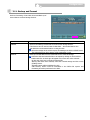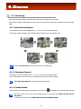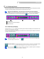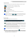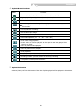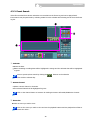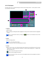
1
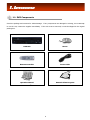
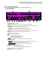
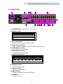
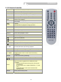
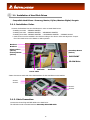
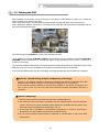
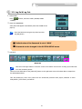
Digital Video Recorder
CDVR-1608R
User Manual
WARNING
FCC Compliance Statement
NOTE : This equipment has been tested and found to comply with the limits for a Class A digital device,
pursuant to part 15 of the FCC Rules. These limits are designed to provide reasonable protection against
harmful interference when the equipment is operated in a commercial environment. This equipment
generates, uses, and can radiate radio frequency energy and, if not installed and used in accordance with
the instruction manual, may cause harmful interference to radio communications. Operation of this
equipment in a residential area is likely to cause harmful interference in which case the user will be
required to correct the interference at his own expense.
2
IMPORTANT SAFETY INSTRUCTIONS
1. Read Instructions
All the safety and operating instructions should be read before the product is operated.
2. Retain Instruction Manuals
The safety and operating instructions should be retained for future reference.
3. Heed Warnings
All warnings on the product and in the operating instructions should be adhered to.
4. Follow Instructions
All operating and use instructions should be followed.
5. Cleaning
Unplug this product from the power outlet before cleaning.
Do not use liquid cleaners or aerosol cleaners. Use a damp cloth for cleaning.
6. Attachments
Do not use attachments not recommended by the product manufacturer as they may cause hazards.
7. Water and Moisture
Do not use this product near water - for example, near a bath tub, wash bowl, kitchen sink, or laundry tub; in a wet
basement; or near a swimming pool; and the like.
8. Accessories
Do not place this product on an unstable cart, stand, tripod, bracket, or table. The product may fall, causing serious
injury to a child or adult, and serious damage to the product.
9. Ventilation
Slots and openings in the cabinet are provided for ventilation and to ensure reliable operation of the product and
to protect it from overheating, and these openings must not be blocked or covered. The openings should never be
blocked by placing the product on a bed, sofa, rug, or other similar surface. This product should not be placed in a
built-in installation such as a bookcase or rack unless proper ventilation is provided or the manufacturer’s
instructions have been adhered to.
10. Power Sources
This product should be operated only from the type of power source indicated on the marking label. If you are not
sure of the type of power supply to your home, consult your product dealer or local power company.
11. Power-Cord Protection
Power-supply cords should be routed so that they are not likely to be walked on or pinched by items placed
upon or against them, paying particular attention to cards at plugs, convenience receptacles, and the point where
they exit from
12. Overloading
Do not overload wall outlets, extension cords, or integral convenience receptacle as this can result in a risk of
fire or electric shock.
13. Object and Liquid Entry
Never push objects of any kind into this product through openings as they may touch dangerous voltage
points or short-out parts that could result in a fire or electric shock. Never spill liquid of any kind on the product.
3
Important Safety Instructions
14. Damage Requiring Service
Unplug this product from the wall outlet and refer servicing to qualified service personnel under the following
conditions:
a) When the power-supply cord or plug is damaged.
b) If liquid has been spilled, or objects have fallen into the product.
c) If the product has been exposed to rain or water.
d) If the product does not operate normally by following the operating instructions. Adjust only those controls
that are covered by the operating instructions as an improper adjustment of other controls may result in
damage and will often require extensive work by a qualified technician to restore the product to its normal
operation.
e) If the product has been dropped or damaged in any way and
f) When the product exhibits a distinct change in performance - this indicates a need for service.
15. Replacement Parts
When replacement parts are required, be sure the service technician has used replacement parts specified by
the manufacturer or have the same characteristics as the original part. Unauthorized substitutions may result in
fire, electric shock, or other hazards.
16. Safety Check
Upon completion of any service or repairs to this product ask the service technician to perform safety checks
to determine that the product is in proper operating condition.
17. Heat
The product should be situated away from heat sources such as radiators, heat registers, stoves, or other
products (including amplifiers) that produce heat the product.
18. Internal Fan
The internal fan rotates at high speed and may cause an accident.
19. Battery
Change the lithium battery after turning off the power of the product.
Check the polarity of the lithium battery while changing and change the lithium battery with the same type
which is in the product or with a similar type recommended by your vendor.
Dispose the lithium battery according to the instructions of the battery manufacturer.
There is danger of explosion when instructions are not followed.
20. Turning On/Off the DVR power.
Do not turn off the power by removal of the power plug.
To turn off the power, click the power button from the front panel.
When the system stops abnormally, the power button might not work.
Click power button for 5 full seconds to turn power off.
Do not turn off the power unproperly or apply shock/vibration to unit while the hard disk is activating.
It may cause hard disk failure or loss of data.
4
INDEX
1. INTRODUCTION
4. OPERATION
1.1. DVR Components……………………........ 6
4.1. Monitoring……………………………..…. 31
1.2. Product Description…………….…………. 7
4.1.1. Multi-Screen Display…………………….
31
1.2.1. Front Panel……………………………. 7
31
4.1.2. Changing Channel…………………….
1.2.2. Rear Panel………………………….…. 9
4.1.3. Freeze Screen………………….…….31
1.2.3. Remote Controller……………………. 10
32
4.1.4. Full Screen Display…………………….
4.2. Monitoring Control………………………. 33
2. INSTALLATION
2.1. Hard Drive…………………………….……. 11
4.2.1. Display………………………………. 33
2.2. Starting the DVR………………..…………. 12
4.2.2. Video…………………………..……. 34
Cautions & Warnings……………..……….. 12
4.2.3. Audio……………………………..…. 34
13
2.3. Log In & Log Out……..……………………….
4.2.4. etc………………………………..….. 35
2.4. CD Booting……………………………………14
4.3. Playback (Search) ………………………. 37
2.5. USB Flash Drive…………...………………….14
4.3.1. Time/Date Search…………………….37
4.3.2. Event Search…………….……….… 40
3. CONFIGURATION
3.1 Configuration Menu…….…………..………. 15
4.3.3. File Search(CD-RW, USB)……...…. 41
3.2. System Setup…………………………..…. 17
4.3.4. Capture…………………………..…. 42
3.3. Camera Setup……………………..………. 19
Image Capture……………..……… 42
3.4. Sensor Setup…………………………….…. 21
Video Clip Copy………………..…… 42
3.5. Network Setup……………………..………. 22
4.4. PTZ Control………………………….………. 44
3.6. Record Setup………………………..……… 24
4.5. Recording……………………………..…..…. 46
3.7. Record Scheduler………………..…………. 26
Panic Recording………………………..…..…46
3.8. Display Setup…………………………….…. 27
Appendix A. Technical Specification
47
3.9. Device Setup & Information…..…….……. 28
Appendix B. Trouble Shooting
48
3.10. Log List……………..………………………. 29
30
3.11. Backup & Format…………………………….
5
1. INTRODUCTION
1.1. DVR Components
Check the package and contents for visible damage. If any components are damaged or missing, do not attempt
to use the unit, contact the supplier immediately. If the unit must be returned, it must be shipped in the original
packing box.
DVR Unit
Mouse
Remote Controller
Power Cable
Operation Manual
Network Client Program
l
6
Introduction
1.2. Product Description
1.2.1. Front Panel
②
①
③ ④
⑤ ⑥
⑦ ⑧⑭ ⑨ ⑮
⑩
⑪
⑫
⑬
1. CD-RW Tray Door : Insert CD.
2. Channel Indicator (1 to 16) : Indicates which channels are operating.
3. POWER : Press to turn on/off power. The power indicator will light up when power is on.
4. REC Indicator : The indicator will blink during recording.
NT Indicator : The indicator will light up during network connection.
AR Indicator : The indicator will light up when sensor is triggered.
5. PANIC : Toggle to start/stop panic recording of all channels with high recording quality.
6. MONITOR : Display the Monitoring Control Menu on the screen.
7. PTZ : Enter the PTZ control mode.
8. SETUP : Enter the Setup Mode.
9. ESC : Clear the Monitoring Control Menu.
Return to a higher Category/Group/Field.
Cancel the selected Field button.
10.
: Insert and Eject CD. You may also push the tray to insert the tray.
11. Operation Keys :
: Activate a function or complete an entry that you have made during setup.
Display the Monitoring Control Menu on the screen.
: Move between categories and change field values.
12. TAB : Move between menu groups.
13. JOG Dial : Change channels during monitoring.
Frame by frame reverse/forward during Playback mode.
14. USB Port : Connection for USB storage device
15. MOUSE Port : Connection for PS2 mouse.
7
Introduction
1.2.2. Rear Panel
③④
②
①
⑤
⑥
16
⑧ ⑨ ⑩⑪
⑦
⑫
1. AC POWER Socket : Supports 110V ~ 220V free volt.
2. SENSOR Terminal
G
G
8
7
6
5
4
3
2
1
* Connect G(Ground) before connecting the sensors.
3. SPOT OUT Connector
- Output connector for Spot Out signal to monitor.
4. VOUT & AOUT Connectors
- Output connector for video(VOUT) and audio(AOUT) signals to monitor.
5. AUDIO INPUT Connectors
- Input connectors for audio signals.
6. VIDEO INPUT Connectors
- Input connectors for video signals.
7. ALARM Output Terminal
8
7
6
5
4
3
2
- Connect the alarm devices in its corresponding numbers.
8. VGA(Monitor) Port
- Connection to PC monitor.
9. S-Video Connector
- Connection to S-Video jack.
10. RMC Connector
- Connection to remote controller extension cable.
11. MOUSE Port
- Connection to Mouse.
8
1
⑬⑭ ⑮
Introduction
12. PTZ Connector
- Connection to PTZ camera.
5
4
9
3
8
2
7
1
6
PIN No.
Explanation
PIN No.
Explanation
1
nRS485
5
GND
9
RS485
2,3,4,6,7,8
Not used
13. LAN Port
- Connection to LAN cable.
14. SW(DIP Switch)
- Adjust the Dip Switch setting according to required functions. The system must be restarted after
adjustments.
Functions
OFF Position(Up)
Color System
ON Position(Down)
NTSC
PAL
Booting
CD Booting
None
Monitor Output
VGA
*TVRGB, Composite, S-Video
* Only PC monitors that support Interlace RGB must be used. Or TVs with RGB jack
(SONY monitors) may be used after connecting RGB and HSYNC to the external SYNC. Switch
between TV↔VGA may be performed only during the Monitoring Mode.
15. TERMINAL
5
4
9
3
8
2
7
1
6
PIN No.
Explanation
PIN No.
Explanation
2
RX
5
GND
3
TX
1,4,6,7,8,9
Not used
PIN No.
Explanation
PIN No.
Explanation
2
RX
5
GND
3
TX
1,4,6,7,8,9
Not used
* Lower serial connection jack : For serial remote control.
16. MODEM Port
5
4
9
3
8
2
7
1
6
9
Introduction
1.2.3. Remote Controller
OSD
OSD On/Off during Monitoring.
PANIC
Panic Recording On/Off.
Numeral Keys
Input numbers during Login/Setup/PTZ.
CAPTURE
Enter video clip/image copy menu during playback.
F/F
Remove image distortion during frame by frame advance.
PREVIOUS
Move to previous category.
NEXT
ESC
Move to next category.
Move cursor left/right/up/down.
PTZ control
Display the menu bar during monitoring, playback, and
capture.
Select/Enable a highlighted category/function.
Stop current operation or return to previous mode.
AUDIO
Audio On/Off.
MONITOR
Enter Monitoring mode.
PTZ
Enter PTZ control mode.
SEARCH
Enter Search(Playback) mode.
SETUP
Enter Setup mode.
PAUSE
Pause during playback.
Direction Keys
MENU
ENTER
/
Fast reverse playback
Playback in reverse/forward direction
Fast forward playback.
FULL SCR
Change to full screen display during Search..
Playback in slow motion(1x→1/2x→1/4→1/8x→1/16)
-/+ SKIP
Increase/Decrease speed during playback.
CH
Change channels during Monitoring/PTZ Control/Playback.
DISPLAY
FREEZE
Change multi-screen display type
Adjust zoom of PTZ camera.
Toggle between zoom 2x and normal view during
monitoring.
Freeze screen during monitoring
SEQUENCE
Automatic sequence display during monitoring.
-/+ ZOOM
/
FOCUS
ID Set
Adjust focus of PTZ camera
Set ID of remote controller.
Same ID must be applied for the DVR and remote
controller.
☞ Press the ID SET button and input the ID using the
numeral keys.
The ID must be set in 3 digits.(If DVR ID is “1” press
“001”)
The ID SET button must remain pressed while
inputting the ID.
PRESET
Enter preset controls of PTZ
IRIS
Adjust aperture of PTZ camera.
10
2. INSTALLATION
2.1. Installation of Hard Disk Drives
※ Compatible Hard Drives : Samsung, Maxtor, Fujitsu, Western Digital, Seagate
2.1.1. Installation Order.
Unscrew the Brackets from the DVR bottom in order to install Hard Drives.
- Installing one HDD : PRIMARY MASTER
- Installing two HDD : PRIMARY MASTER → SECONDARY MASTER
- Installing three HDD : PRIMARY MASTER → SECONDARY MASTER → PRIMARY SLAVE
* Hard Drives must be installed in the DVR according to the above order and adjust the Jumper
Pin of the Hard Drive to the Master or Slave position.
Bracket 2
Bracket 1
Primary Slave
(Above)
Primary Master
(Below)
Secondary Master
(Below)
DVR FRONT
CD-RW Drive
IDE Cable
Power Cable
IDE Cable
- Fasten 2 screws on each side of the HDD bracket to fix the Hard Drives to the bracket.
Screw 1
Screw 2
Screw 3
Screw 4
2.1.2. Cable Connection.
Connect the Power Plug and IDE Cable to the Hard Drive.
The CD-RW must be connected with the Secondary Slave IDE Cable.
11
Installation
2.2. Starting the DVR
After installing the hard disk, set the DIP switch to the NTSC or PAL position to match your equipment
before turning on the power of the DVR.
Then, connect the power cord and press the power button until the LED lights up to start the DVR.
When starting the DVR for the first time, formatting of the hard disk will commence automatically and the
DVR will be initialized as follows.
The DVR will perform “S.M.A.R.T.” check of the installed hard disk.
If no problem is detected [S.M.A.R.T. PASS] will be indicated and if a problem is detected [S.M.A.R.T.
FAILURE] will be indicated and a warning will appear on the monitoring screen every 1 minute for a
duration of 5 seconds.
The hard disk capacity indicated may be smaller than the capacity declared by the hard disk producer. This
difference may occur due to the difference in measure units and therefore is not a defect.
If the hard disk detected has not been formatted, recording will start after the formatting is completed.
※ S.M.A.R.T. (Self Monitoring, Analysis and Reporting Technology)
S.M.A.R.T. is a reliability prediction technology to anticipate the failure of a hard disk drive with
sufficient notice to allow a system or user to back up data prior to a drive’s failure.
If the controller detects problems in the disk drive reliability, it will release a warning to the
user. In such a case, the use of the disk drive should be stopped immediately and have it
examined.
※ Cautions & Warnings
1. Press the Power button on the DVR until the Power Indicator lights up.
2. The Hard Disk used in this DVR is compatible with the Windows OS by using the FAT32 file
system. However, we cannot guarantee safety against the possibility that the system may
crash with vaccine programs such as Anti-Virus, V3, etc.
3. If the Hard Disk is formatted in the Windows environment, it should be performed in
Windows XP or a higher edition and must use the FAT32 format.
4. Do not remove devices during backup or playback of recorded data. It may cause DVR
malfunctions.
12
Installation
2.3. Log In & Log Out
1. Select USER
Using
~USER5)
buttons, select the USER. (ADMIN, USER1
2. Enter the PASSWORD
A Key Panel will appear automatically when the LOGIN screen
pops up.
Enter the Password using the Key Panel and click
the [OK] button.
Key Panel
※ Default value of the Password is set at “0000”.
※ Password can be changed in the SYSTEM SETUP menu.
3. LOG OUT
Menu Bar
Click the mouse right button or move the cursor to the bottom of the screen to bring up the Menu bar
on to the monitoring screen.
Click the mouse left button on the [LOG OUT] button on the right hand corner of the Menu Bar to escape from
the Administrator Mode.
This will prohibit any other users other than the authorized personnel with proper password to enter
PLAY(Search), PTZ Control, and SETUP
13
Installation
2.4. CD Booting
When you face problems with the DVR program or want to re-install or upgrade the firmware without
entering the DVR Setup menu please take the following steps.
1. Adjust the DIP Switch located in the rear panel of the DVR to the CD position(Down) and turn
on the DVR power.
2. Insert the CD containing the DVR Firmware.
The name of the Firmware is “DVRSYS” and in
this directory, the following folders must exist.
- CDVR BMP
- FONT
- FW
3. Firmware installation will proceed automatically once the Firmware CD is inserted. The CD
will eject automatically once the installation is completed.
4. Take out the CD and adjust the DIP Switch(CD Switch) to the Off position(Up).
The DVR will
will automatically re-boot.
5. Repeat the above procedure if the DVR fails to re-boot.
2.5. USB Flash Drive
• This DVR supports Hi-Speed USB 2.0 Flash Drives.
- Use of Full Speed USB 2.0 Flash Drives may result in slow backup speed or capture speed.
• Please note that the USB must be formatted using the DVR Formatting function.
- Please follow the formatting instructions provided in CONFIGURATION – BACKUP in page33.
14
3. CONFIGURATION
3.1. Configuration Menu
SYSTEM
CAMERA
SENSOR
LANGUAGE
CAMERA NAME
SENSOR
ID(DVR)
MOTION DETECTION
CAMERA LINK
DATE TYPE
MASKING AREA
ALARM LINK
TIME DATE
SENSITIVITY(CAMERA)
OPERATION TIME
DST
COVERT
TYPE
TRANSPARENCY(GUI)
COLOR SETTING
OPERATION MODE
ADMIN PASSWORD
BRIGHTNESS
RECORDING DWELL TIME
MOUSE SENSITIVITY
CONTRAST
OUTPUT DWELL TIME(ALARM)
USER(NUMBER)
HUE
USER PASSWORD
PTZ SETTING
USER AUTHORITY
ID
COLOR SYSTEM(NTSC/PAL)
DRIVER
S/W VERSION
BAUD RATE
UPGRADE(SETUP, F/W, BMP)
DATA BIT
FACTORY DEFAULT(RESET)
PARITY
STOP BIT
NETWORK
RECORD
SCHEDULER
IP TYPE
RESOLUTION
SCHEDULE
PORT
WATERMARK USE
CONTINUOUS
IP ADDRESS
WATERMARK STRENGTH
MOTION
GATEWAY
WATERMARK KEY
MOTION+SENSOR
SUBNET MASK
RECORD TIME STAMP
SENSOR
DNS SERVER
AUDIO RECORD
NONE
SMTP SERVER
FPS(RECORDING SPEED)
MAC ADDRESS
QUALITY
E-MAIL SERVER ID
E-MAIL SERVER PASSWORD
E-MAIL SENDER
E-MAIL RECEIVER
PPPOE ID
PPPOE PASSWORD
DVR NAME
EVENT MAIL
15
COPY SCHEDULE
Configuration
DISPLAY
MULTI-DISPLAY
DEVICE
DISK MANAGEMENT
LOG LIST
EVENTS
SEQUENCE MODE(CAMEO)
END OF DISK
POWER
SEQUENCE DWELL TIME
FULL DISK ALARM
SENSOR
FULL DISK PRE-ALARM(5%)
RECORD
SMART FAILURE
CAMERA
VIDEO ADJUSTMENT
FLICKER CANCEL
COLOR DIFFUSION
VGA DE-INTERLACE
DEVICE INFORMATION
LAN
DEVICE
BACKUP
SIZE
SETUP
SEQUENCE DWELL TIME
TEMPERATURE
TIME
SENSOR ACTIVATION
RAW READ ERROR RATE
CHANNELS
RE-ALLOCATED SECTOR COUNT
CALENDAR
SPOT OUT
SEEK ERROR RATE
BACKUP & FORMAT
FORMAT
BACKUP
16
Configuration
3.2. System Setup
Before starting your DVR for the first time, you should
establish the initial settings. This includes categories
such as Language, DVR ID, Date and Time, DST,
Password, User Authorization.
Click the
button on the Menu Bar to enter
SETUP and the [SYSTEM] Setup screen will
appear on the monitor. Click on the settings(field)
to change the values.
Click on the
button after changing the setup values.
CATEGORY
LANGUAGE
DEFAULT
VALUE
ENGLISH
FUNCTION & OPERATION METHOD
• Select GUI(Graphic User Interface) Language
• The display will change immediately according to the selected
language.
• If the new values are not saved when exiting [SETUP], the
settings will return to its previous values.
Turn the mouse wheel to change the Language.
ID
0
• Assign an ID number for the DVR
• When using several DVRs, each DVR will be differentiated with
this ID number.
• Input Range : 0~255
Use pop-up Key Panel or turn the mouse wheel to change the
number.
DATE TYPE
YYYY-MM-DD
• Select DATE indication method.(YYYY-MM-DD, MM-DD-YYYY,
DD-MM-YYYY.)
Turn the mouse wheel to change the Date Type.
• Adjust the Time and Date.
• A calendar will appear when the Time & Date Field is selected.
• Date is available from January of the DVR production year to end
TIME DATE
of year 2099.
buttons on the calendar to change the Month.
Use the
Click on the Date with mouse left button and change the Time
by turning the mouse wheel or clicking the
buttons.
DST
NO
• Select whether to apply the DST(Daylight Saving Time)
Turn the mouse wheel to select between YES or NO..
TRANSPARENCY
0
• Set the transparency level of the Graphic User Interface(GUI).
• The GUI will appear more transparent with lower input values
• Input Range : 0~10
Turn the mouse wheel to change the input value or use the
pop-up Key Panel.
ADMIN PASSWORD
0000
• Register Password of the DVR Administrator.
• Max. 8 characters(Letters and numerals) can be used.
Use the pop-up Key Panel to change the password.
17
Configuration
CATEGORY
MOUSE SENSITIVITY
DEFAULT
VALUE
2
FUNCTION & OPERATION METHOD
• Set the Mouse Sensitivity level.
• Input Range : 1(Slow)~3(Fast)
Turn the mouse wheel to change the input value.
USER
1
• Assign the number of authorized Users having access to the DVR.
• Max. number of Users : 1~5 persons.
• User Password and Authority Level will need to be assigned for
each Users.
• Register the User Password and Authority Level after selecting the
User.
Turn the mouse wheel to change the User.
USER PASSWORD
0000
• Register the Password of the selected User.
• Max. 8 characters(Letters and numerals) can be used.
Use the pop-up Key Panel to change the password.
USER AUTHORITY
COLOR SYSTEM
NONE
NTSC / PAL
S/W VERSION
UPGRADE
IMPORT
• Assign the Authority Level of the selected User.
• Assign which mode/modes(PLAY, PTZ, RECORD CONTROL, USB)
the User is permitted to access.
Click on the mode or modes the User is permitted to access.
The button will be highlighted in pink when selected.
• Displays the current Color System selected for the DVR.
• Setting values : NTSC, PAL
The DIP Switch in the DVR rear panel should be positioned to
the Color System applicable in your region before turning on
the DVR power.
• Displays the installed Software version of the DVR.
• Upgrade Setup Values, Firmware and BMP Image(GUI) files
: Setup Values
: Firmware
: Image files used in the GUI.
: Upgrade(Download) Firmware, Setup Information,
BMP files to the DVR from a CD or USB memory.
: Copy Firmware, Setup information, BMP files of the
DVR to a CD or USB memory.
: Select the CD-RW or USB.
DVR UPGRADE : Select the Upgrade category(Setup, Firmware,
BMP) and click on IMPORT. Click DEVICE and
select the storage device from the pop-up
menu and click the START button.
Copy to CD or USB : Select the Upgrade category and click on
EXPORT. Click DEVICE and select the storage
device from the pop-up menu and click the
START button.
• All settings in SETUP will be reset to the initial Factory default
values
Click the FACTORY DEFAULT button with the mouse left button.
• All settings in the SYSTEM Setup will return to its Previous values.
Click the Pre-Value button with the mouse left button.
• All settings in the SYSTEM Setup will return to its factory default
values.
Click on the DEFAULT button.
18
Configuration
3.3. Camera Setup
In Camera Setup, you may designate Motion Detection
and Masking Areas, select Covert function, and adjust
the Color and PTZ settings for individual/all cameras
connected to the DVR.
Select the camera number from the channel
buttons displayed at the top of the screen for
individual camera setup. You may click on the
button to apply same setting values for all cameras for
Sensitivity, Covert, and Color Setting.
※ Select the Camera before changing the Camera
settings..
Save confirmation window will appear when changing to another camera number if setup values have been
changed.
CATEGORY
NAME
DEFAULT
VALUE
FUNCTION & OPERATION METHOD
CH1
• Assign the Camera Name to display on the On Screen Display
(OSD).
• Max. 8 characters(Letters and numerals) can be used.
Use the pop-up Key Panel to input characters..
MOTION DETECTION
MASKING AREA
NONE
NONE
• Designate the Motion Detection Area
Click the [MOTION DETECTION] button, and then designate the
Motion Detection Area by clicking on the desired areas in the
view screen. Designated area will be highlighted in blue.
Clicking on the [ALL] button will designate the entire area.
Clicking on the [CLEAR] button will clear all designated areas.
• Designate a specific area that needs to be hidden during
monitoring and recording.
• Designation of Masking area in the semitransparent area on the
right hand side of the view screen is not possible.
Click on an area in the view screen to designate the Masking
Area. Click the [CLEAR] button to cancel the Masking area.
SENSITIVITY
80
• Set the Motion Detection Sensitivity level.
• Recording will perform continuously if the sensitivity level is set at
100.
• Input Range : 10~100
COVERT
COLOR SETTING
Use the pop-up Key Panel or turn the mouse wheel to change
the input value.
• The selected camera will not be displayed on the monitor.
• Recording of the selected camera will continue.
Click the check box to apply Covert camera function.
• Set the Brightness, Contrast , Hue level of the selected camera
• Input Range : 0~10
Use the pop-up Key Panel or turn the mouse wheel to change
the level and click on
or
button.
19
Configuration
CATEGORY
PTZ SETTING
DEFAULT
VALUE
FUNCTION & OPERATION METHOD
• Assign the PTZ ID, Driver, Baud Rate, Data Bit, Parity, Stop Bit
for the selected PTZ Camera
• Input Range :
- PTZ ID : 0~255
- PTZ Drivers : PELCO-D, PELCO-P, PANASONIC, PT-A100L,
DOME1, DOME2, HSDN-251N, WPT-101, SJ-2819, SK2162D, DSC-230, GROOM-D106, CAZ1723, VC-C4, SCCC4201, CRR1600T, SRX-100B, VVK-3000, ORX-1000
- Baud Rate : 300 ~115,200
- Data Bit : 7 ⇔ 8
- Parity : NONE ⇔ ODD ⇔ EVEN,
- Stop Bit : 1 ⇔ 2
Use the pop-up Key Panel or turn the mouse wheel to change
the input values.
Click the [TEST] button to test whether the PTZ camera is
operating properly.
Click the
or
button after completing the PTZ
setting.
20
Configuration
3.4. Sensor Setup
In Sensor Setup, you may designate Camera and Alarm
(Output) Link for each Sensors.
Select the Sensor from the Sensor numbers
displayed at the top of the screen and then
make the necessary linkage with the Camera and Alarm
(Output).
Save confirmation window will appear when changing to
a new Sensor number if setup values have be changed.
CATEGORY
DEFAULT
VALUE
• Assign the Camera that is to be connected to the Sensor.
CAMERA LINK
Click the Camera channel or channels that is to be linked to the
Sensor.
• Assign the Output(Alarm) that will activate when the Sensor is
triggered.
ALARM LINK
OPERATION TIME
FUNCTION & OPERATION METHOD
0~24
Click the Output Channel or Channels that is to be linked to the
Sensor.
• Set the Time for which the Sensor will operate.
• Input Range : Between 0~24(Unit : Hour)
Turn the mouse wheel to change the time.
TYPE
OPERATION MODE
RECORDING DWELL TIME
NO
NORMAL
0
• Select the Sensor Type
• Please refer to the Sensor Manual to select the correct type.
Turn the mouse wheel to select between NO(Normal Open) and
NC(Normal Closed)
• Select the Monitoring Screen Display type when the Sensor is
triggered.
- NORMAL : Display video in 16 channel multi-screen display.
- INTENSIVE : For 1:1 Camera and Sensor link, the activated
camera view will appear in Full Screen Display and
the DVR internal buzzer will beep while the Sensor
is activated.
• If several Cameras are linked to the Sensor, the Intensive mode
cannot be applied.
Turn the mouse wheel to select between NORMAL and
INTENSIVE.
• Set the length of time you would like to record for the associated
event.
• Input Range : 0~600 Seconds
Turn the mouse wheel to change the Recording Dwell Time.
OUTPUT DWELL TIME
0
• Set the length of time you want the Output(Alarm) activated.
• Input Range : 0~600 Seconds
Turn the mouse wheel to change the Output Dwell Time.
21
Configuration
3.5. Network Setup
Remote access and control of the DVR through the
internet may be performed with the Network Client
Software included in this package. Configuration of
the Network settings is required to connect the DVR
to the internet.
Select the IP Type that meets your network
environment and set up the appropriate LAN
parameters.
CATEGORY
IP TYPE
PORT
IP ADDRESS
GATEWAY
DEFAULT VALUE
FIXED IP
7050
192.168.123.98
192.168.123.254
FUNCTION & OPERATION METHOD
• Select the IP Type : FIXED ⇔ AUTO ⇔ PPPOE
Turn the mouse wheel to select the IP Type.
Fields that do not require any input will be highlighted in green.
• Set the Port number.
• Input Range : 0~65000
Use the pop-up Key Panel or turn the mouse wheel to input the
numbers.
• Set the IP Address
• Input Range for each field : 0~255
Use the pop-up Key Panel or turn the mouse wheel to input the
numbers.
• Set the Gateway Address
• Input Range for each field : 0~255
Use the pop-up Key Panel or turn the mouse wheel to input the
numbers.
SUBNET MASK
DNS SERVER
SMTP SERVER
MAC ADDRESS
255.255.255.0
210.114.220.41
0 .0 .0 .0
• Set the Subnet-Mask Address
• Input Range for each field : 0~255
Use the pop-up Key Panel or turn the mouse wheel to input the
numbers.
• Set the DNS Server
• Input Range for each field : 0~255
Use the pop-up Key Panel or turn the mouse wheel to input the
numbers.
• Set the SMTP Server
• Input Range for each field : 0~255
Use the pop-up Key Panel or turn the mouse wheel to input the
numbers.
• Set the MAC Address
• Input Range for each field : 0~255
Use the pop-up Key Panel or turn the mouse wheel to input the
numbers.
22
Configuration
CATEGORY
E-MAIL SERVER ID
DEFAULT
VALUE
ADMIN
FUNCTION & OPERATION METHOD
• Set the E-mail Server ID.
• Max. 16 characters can be used.
Use the pop-up Key Panel to input characters
PASSWORD
0000
• Set the E-mail Server Password.
• Max. 16 characters can be used.
Use the pop-up Key Panel to input characters.
E-MAIL SERVER LOGIN
NOT USE
• Select whether e-mail server Login is required when sending an
event e-mail.
Click on the [USE] [NOT USE] button to select between Use or
Not Use.
• Set the e-mail address of the Sender.
• Max. 50 characters can be used.
E-MAIL SENDER
Use the pop-up Key Panel to input characters.
• Set the e-mail address of the Receiver.
• Max. 50 characters can be used.
E-MAIL RECEIVER
Use the pop-up Key Panel to input characters.
PPPOE ID
ADMIN
• Set the ID required for PPPOE networking.
• Max. 128 characters can be used.
Use the pop-up Key Panel to input characters.
PPPOE PASSWORD
0000
• Set the Password required for PPPOE networking.
• Max. 128 characters can be used.
Use the pop-up Key Panel to input characters.
DVR NAME
• Assign a Name for the DVR.
• Max. 50 characters can be used.
Use the pop-up Key Panel to input characters.
EVENT MAIL
• Set for which Events e-mail notification is to be activated.
• When an Event (Power, Sensor, Record, Camera, Network,
Backup, Setup, Time) occurs, e-mail notice will be relayed to the
designated recipient.
Click the Event buttons for which e-mail notification is required.
Selected events will be highlighted in pink.
23
Configuration
3.6. Record Setup
Video Recording Speed(FPS) and Quality, Video
Resolution, Watermarking(Video Authentication).
Time Stamping, and Audio Recording can be set
up in this menu.
※ Resolution, Watermark, Time Stamp, Audio
Recording can be configured only in two Groups.
- Group A : Channels 1~8
- Group B : Channels 9~16
※ Recording Speed and Quality can be set up for
each individual cameras or all cameras.
Save confirmation window will appear when changing to another camera number if setup values have been
changed.
DEFAULT
VALUE
CATEGORY
352x240(NTSC)
352x288(PAL)
RESOLUTION
FUNCTION & OPERATION METHOD
• Set the recording resolution.
NTSC : 352x240, 720x240, 352x480, 720x480
PAL : 352x288, 720x288, 352x576, 720x576
Turn the mouse wheel to select the Resolution Type.
• Digital encoding will be made on images for authentication.
• Select whether to apply Watermark or not.
• Watermark Strength and Key must also be set.
*WATERMARK SETUP
WATER
MARK
0
STRENGTH
WATERMARK KEY
0
Click on the check box to apply. The check box will be
highlighted in yellow when applied.
• Set the Watermark Strength.
• Input Range : 0~4
Turn the mouse wheel or use the pop-up Key Panel to select
the Strength.
• Set the Watermark Key.
• Input Range : 0~15
Turn the mouse wheel or use the pop-up Key Panel to select
a Key.
RECORD TIME STAMP
AUDIO RECORD
• Overlay the Time of Recording on the video for authentication.
• Select whether to apply Record Time Stamp or not.
Click on the Check box. The check box will be highlighted in
yellow when applied.
• Select Audio Recording channels.
Click on the Audio Channel buttons. The selected channels
will be highlighted in pink.
24
Configuration
CATEGORY
CAMERA
DEFAULT
VALUE
CH1
FUNCTION & OPERATION METHOD
• Select the camera for setting up the Recording Speed(FPS)
and Recording Quality.
*FPS
QUALITY
15
MIDDLE
Click
button to apply the same setting values for all
cameras or click on one channel to set different settings for
each cameras..
• Set the Recording Speed : FPS(Frames per Second)
• Recording will not operate if value is set at “0”.
• Input Range : 0~30 for NTSC, 0~25 for PAL
Turn the mouse wheel or use the pop-up Key Panel to
change the FPS level.
• Set the Video Quality level.
• Input Range :
- LOW ⇔ MIDDLE ⇔ HIGH ⇔ SUPER
Turn the mouse wheel to change the quality level.
※ WATERMARK is a technology which overlays hidden digital codes to recordings to counter forgery
or tampering of the original data.
※ FPS : If the total FPS of the entire channels used exceeds the max. FPS of the DVR(240fps/NTSC,
200fps/ PAL)the DVR will automatically decrease the FPS level of each channels uniformly.
25
Configuration
3.7. Record Scheduler
Recordings can be scheduled for each individual or
all cameras based on various recording conditions
including Continuous, Motion, Sensor, Motion+Sensor.
Select the camera number from the channels
displayed at the top of the screen, and then
select the recording conditions for each weekdays.
Or click on
button beside the channel buttons to
apply the same recording
conditions for all cameras, or apply different conditions
for each camera by selecting the appropriate channel.
Save confirmation window will appear when changing to another camera number if setup values have been
changed.
CATEGORY
DEFAULT
VALUE
FUNCTION & OPERATION METHOD
RECORDING
• Select the Recording Condition for each Day and Time.
CONDITION
CONTINUOUS(Green) : Record continuously.
MOTION(Light Blue) : Start recording when motion is
detected.
MOTION+SENSOR(Blue) : Start recording when SENSOR is
activated
SENSOR(Orange) : Start recording when MOTION & SENSOR
is activated
Do not record.(Gray)
ALL
COPY CAMERA
Click on the small square buttons on the Weekday/Time Table
to change the recording condition.
• Apply the same recording condition for the selected weekday or
the entire week..
Click on the relevant
button to change the recording
condition. The recording condition will change with each click.
• The recording condition for a camera can be copied to another
camera.
Select a camera number to which the copy is to be made by
clicking on the
or
and click the
button.
26
Configuration
3.8. Display Setup
Multi-Screen Sequence Display and Spot Monitoring may
be set up in this menu and adjustments of video distortion
or problems may be made.
CATEGORY
MULTI-DISPLAY MODE
DEFAULT
VALUE
NORMAL
SEQUENCE MODE
MULTI-DISPLAY MODE
• Set whether to use the Sequence or Cameo function.
• NORMAL : The displayed channels will be displayed briefly on
screen before changing to the next channel in the
sequence list.
• CAMEO : The screen on the bottom right hand corner will display
the remaining channels in sequence mode during
4 & 9 multi-screen display. In the 13 multi-screen
display mode, the middle screen will act as the cameo
screen.
Turn the mouse wheel to change between NORMAL ⇔ CAMEO
10
• The Sequencing feature allows a camera to be displayed briefly on
screen, before advancing to the next camera.
SEQUENCE DWELL TIME
FLICKER CANCEL
FUNCTION & OPERATION METHOD
• Set the sequence dwell time.
• Input Range : 1~600 Seconds
YES
Turn the mouse wheel or use the pop-up Key Panel to change
the dwell time.
• Select this feature if the GUI becomes shaky when using
composite output
Turn the mouse wheel to select between YES ⇔ NO.
COLOR DIFFUSION
NTSC : 8
PAL : 18
• Set to compensate/correct Color Diffusion when using composite
video output
• Input Range : 0~32
VGA DE-INTERLACE
BOB
Turn the mouse wheel for adjustment.
Adjust the level based on the status of the 3 color boxes.
• When viewing video in the progressive(VGA) scan mode, the
interlaced image is transformed to the progressive image. And if
there is no moving images, horizontal lines(Tearing) will appear
on the screen. Selecting “BOB” will make the tearing disappear
and if there is no moving images on screen, selecting “WEAVE”
will provide a clearer image.
Turn the mouse wheel to change between BOB ⇔ WEAVE.
SPOT OUT
0
SEQUENCE DWELL TIME
SENSOR ACTIVATION
Disable
• Set the channel sequence dwell time for the SPOT Monitor.
• Input Range : 0~600 Seconds
Turn the mouse wheel or use the pop-up Key Panel to change
the dwell time.
• Set whether to use Spot output when sensor is triggered.
Click on the check box to enable/disable.
27
Configuration
3.9. Device Setup & Information
Hard disk drive and external memory device information
is provided in this menu
You may decide whether to Overwrite or Stop recording
when the capacity of the installed hard disk drive is full.
And select the notification method.
CATEGORY
END OF DISK
FUNCTION & OPERATION METHOD
• Select whether to STOP or OVERWRITE recording when the HDD capacity is full.
Turn the mouse wheel to select between STOP ⇔ OVERWRITE
FULL DISK ALARM
• Select the notification method when the HDD is full.
BEEP : Beeper in the DVR will be activated.
MAIL : E-Mail will be transmitted to the designated person.
Click on the check box to enable /disable.
FULL DISK PRE-ALARM
(5%)
• Select the notification method when there remains only 5% HDD capacity
BEEP : Beeper in the DVR will be activated.
MAIL : E-Mail will be transmitted to the designated person.
Click on the check box to enable /disable.
SMART FAILURE
• Select the notification method when SMART(HDD) Failure occurs.
BEEP : Beeper in the DVR will be activated.
MAIL : E-Mail will be transmitted to the designated person.
Click on the check box to enable /disable.
DEVICE INFORMATION
• Select the memory device to check the device information and status.
- Device Type
- Memory Size
- Temperature
- Raw Read Error Rate
- Re-Allocated Sectors count
- Seek Error Rate
Click on the button of the memory device you wish to check.
28
Configuration
3.10. Log List
Log List of various events involving Power, Sensor,
Recording, Camera, LAN, Backup, Setup, and Time
changes can be searched for any dates.
CATEGORY
EVENTS
FUNCTION & OPERATION METHOD
• Select the event type you wish to search.
All : Log list of all events.
PWR : Log list of Power On/Off
SENS : Log list of Sensor input.
REC : Log list of Recording Start/Stop.
CAM : Log list of Camera On/Off.
LAN : Log list of LAN connections.
BACKUP : Log list of Backup executions.
SET : Log list of Setup Configuration changes.
TIME : Log list of System Clock adjustments.
CHANNEL
Click on the relevant event button. The selected event button will be highlighted
in pink.
• Select the channel.
CALENDAR
Click on the channel button. The selected channel button will be highlighted in
pink.
• Select the date.
Use
buttons to select the Month and click on the day
29
Configuration
3.11. Backup and Format
Perform Formatting of hard disk drives and Back Up of
stored data to external storage devices.
CATEGORY
FORMAT
FUNCTION & OPERATION METHOD
• Perform Formatting of Hard Disk Drives and other storage devices.
• This function can be used to erase CD-RW disks. All recorded data on the
CD-RW disk must be erased before re-using the disk.
BACKUP
Select the storage device which requires Formatting and click the START button.
The selected storage device button will be highlighted in pink.
• Back up recorded data from the Hard Disk Drive to external storage.
Select the HDD and select the files to be copied by clicking on the check box
beside each files. A check sign will appear in the check box when selected.
Re-click the check box to cancel the selected file.
After the files have been selected, select the external storage and click on the
[START] button.
Selected buttons will be highlighted in pink.
USB Memory Device must be formatted in the FAT32 file system and
formatting should be performed in the DVR.
30
4. OPERATION
4.1. Monitoring
During the Monitoring Mode, video data from cameras are relayed live to monitors.
Multi-Screen Display, Channel Shift, Screen Freeze, and Full-Screen Display are supported in the Monitoring
Mode.
4.1.1. Multi-Screen Display
The monitoring screen can be displayed in 1 / 4 / 9 / 13 / 16 channel Multi-Screen.
The Monitor Display will shift to the next Multi-Screen Display type in the following order.
Full Screen
4 Screen
16 Screen
9 Screen
13 Screen
Click the mouse wheel to change the multi-screen display type.
4.1.2. Changing Channel
Changing the channel is possible only in 1 / 4 / 9 / 13 multi-screen display modes.
In the 13 channel multi-screen mode, the channels in the center screen will change
Turn the mouse wheel to increase and decrease channels.
4.1.3. Freeze Screen
You may freeze a live image during monitoring. The freeze icon
will appear on the selected channel screen.
Place the mouse cursor on the screen(Channel) that is to be frozen and double click the mouse
left button
In order to resume live view, double click the mouse left button again.
31
Operation
4.1.4. Full Screen Display
A channel can be selected to be viewed in Full Screen during multi-screen monitoring
Place the mouse cursor on the screen(Channel) and click the mouse left button
In order to return to the previous multi-screen monitoring mode, re-click the mouse left button.
32
Operation
4.2. Monitoring Control
Multi-Screen Display selection, Video/Audio Channel selection, OSD change, Record, Status(Sensor, Network
Connection, Recording) Display, and Video Reset can be performed in this mode.
Click the mouse right button or move the cursor to the lower part of the monitoring
screen to make the Menu Bar(Shown below) appear on screen. The Menu Bar will disappear from
the screen automatically after one minute and clicking the EXIT
①
①
②
③
②
button can also make it disappear.
③
Category Menu
Sub-Menu for the selected Category
Main Mode Menu
4.2.1. Multi-Screen Display
Full Screen and 4 / 9 / 13 / 16 Multi-Screen Display types and Sequence Display can be selected from the
Sub-Menu of the Monitoring Control Bar.
In the 13 channel Multi-Screen display type, the middle screen is used for sequence display of all channels
or display of a selected channel..
Multi-Screen Display : Click the MULTI
button and click on the multi-screen display type
you wish to apply in the sub-menu
Sequence Display : The Sequencing feature allows a channel or channels to be displayed briefly
on screen before changing to the next channel in the sequence list.
Click the sequence
button and the channels will change in repeated sequence according to
the sequence dwell time applied in [SETUP] - [DISPLAY]
33
Operation
4.2.2. Video
Video input and recording status of all channels will be displayed on the Menu Bar..
During 13 channel multi-screen display, the selected channel will be displayed in the center screen.
Current status of each video channels are displayed based on different colors.
GRAY : No input signal.
BLUE : Input signal exists but recording not in progress.
PINK
: Input signal exist and recording in progress.
GREEN : Selected channel.
Click the VIDEO
button and the channel buttons will appear in the sub-menu. Click the
channel button you wish to see
4.2.3. Audio
Displays the current status of each audio channels and you may select which audio channel you wish to
hear.
Current status of each audio channels are displayed based on different colors.
GRAY : No recording is in progress.
PINK
: Recording in progress.
GREEN : Selected channel.
: Audio ON
: Audio OFF
Click the AUDIO
button and the channel buttons will appear in the sub-menu. Click the
channel button you wish to hear.
34
Operation
4.2.4. etc
OSD Change, Recording On/Off, Status(Sensor, Network Connection, Recording) Display, and Video Reset can
be performed in this menu.
1.
Change OSD(On Screen Display)
You may select to display or hide OSD on the screen during monitoring.
Click the OSD
button and the OSD will change in the following order :
Time+Channel → Channel → Time → HDD Status Bar→ Off
HDD(Hard Disk) Status Bar
Disk Capacity, Disk Status, and Used Capacity/Total Capacity information is displayed in the Status Bar.
Used/Total Memory
HDD1[152G], STATUS[EXCELLENT]
9%
Capacity Status Bar
※
2.
14/154GB
Capacity Used
The Status bar will disappear automatically after 10 seconds.
Recording On/Off
Start Recording when not in recording mode or Stop Recording during record mode. Recording will be
performed based on the settings applied in [SETUP].
※
Authorized user password entry will be required in order to stop recording.
Click the RECORD
3.
button to Start/Stop recording.
Video Reset
This function can be used to correct bad video conditions during monitoring and playback.
Click the VIDEO RESET
button when you experience bad video conditions.
35
Operation
4.
Sensor & Network Status
Status of Sensor, Network Connection, Recording are displayed on the Status Bar.
•
When a Sensor is triggered the corresponding Sensor channel will be highlighted in pink..
•
When a Network connection occurs, the icon will be highlighted in pink.
•
The Record icon will blink continuously if recording is in progress.
※
※
The Status Bar will pop-up automatically when Sensor and Network connection occurs.
The Status Bar will disappear automatically after 10 seconds, or it can be cleared by clicking the
button.
36
Operation
4.3. Playback (Search)
Playback/Search and Capture of recorded video/data may be performed in this mode.
Click the PLAY
button to enter Playback(Search) mode.
Search can be performed in three different methods. Click the SEARCH
button and select the search
method from the Sub-Menu.
•
Time/Date Search
•
Event(Sensor) Search
•
File Search
4.3.1. Time/Date Search
Recorded video may be searched based on Time & Date.
①
⑤
②
④
③
1. Calendar
• Select the date.
• Dates containing recording data will be highlighted in orange and the selected date will be highlighted
in green.
Move to previous/next month by clicking the
relevant day.
37
buttons on the calendar. Then click the
Operation
2. Channel/Time Table
• Numbers 0~24 represents Time and recording information is displayed on the table for 8 channels.
Recording information of channels 1~8 will appear on the Table.
Recording information of channels 9~16 will appear on the Table.
Orange : Recording video data exists
Gray : No video data.
Green : Selected for playback.
Blue : Sensor activated video data exists.
Switch from Search Screen to Full Screen Display or from Full Screen Display to the
Search Screen.
Channels are divided into two groups of 1~8 and 9~16 and you may select which group you
wish to view by clicking on the
or
button. The selected button will change to
green.
Click on the relevant square button on the Channel/Time Table to start the video clip
3. Playback Scroll Bar
Displays the playback progression rate of the selected video clip
• The scrollbar represents one hour and each scale mark represents 10 minutes .
•
Return to the beginning of the selected video clip during playback and playback will not resume
unless otherwise instructed. If this button is clicked at the beginning of the video clip, it will
move back to the previous hour and resume playback. If no video clip exists in the previous
hour it will search for the most recent previous video clip.
•
Advance to the end of the selected video clip during playback and stop. If this button is clicked
at the end of the video clip, playback will resume from the next hour. If no video clip exists in
the next hour, it will search for the nearest subsequent video clip.
Click on the Playback Scroll Bar to view video of the selected period in the one hour time frame.
※
8 Channels are displayed in Playback and clicking on the
9 channel multi-screen
button from the menu bar during Full Screen playback will allow you to move between
the two groups Channels 1~8 and Channels 9~16.
38
Operation
4. Playback Button Functions
Button
Function
• Decrease playback speed ( 1x → 1/2 → 1/4x → 1/8x → 1/16x )
• Regain playback speed ( 1/16x → 1/8x → 1/4x → 1/2 → 1x )
• Correct bad video conditions.
• Correct image distortion during still frame playback.
※ Operates only on monitors with vertical pixel size above 480 for NTSC and
576 for PAL.
• Turn On/Off audio recording.
• Save a video clip or image.
• Fast reverse playback ( 2x → 4x → 8x → 16x → 32x)
• Fast forward playback ( 2x → 4x → 8x → 16x → 32x)
• Pause video during playback.
• Paused video will resume playback at the speed it was being played if the
button is re-clicked.
• Frame by frame forward playback.
• Frame by frame reverse playback.
• Pause playback.
• Slow playback( 1x → 1/2 → 1/4x → 1/8x → 1/16x )
• Recording indicator. (The dot will blink in red during recording)
• 1x Playback in forward/reverse direction.
5. Playback Information
• Channel, Date, and Time Information of the video clip being played will be displayed in this window.
39
Operation
4.3.2. Event Search
Video files recorded from Sensor activation are recorded into the Event Log and can be played back.
Event search may be performed by selecting a date from the calendar and selecting the file from the Event
log list.
②
①
③
1. Calendar
• Select the date.
• Dates containing recording data will be highlighted in orange and the selected date will be highlighted
in green.
Move to previous/next month by clicking the
buttons on the calendar.
Then click the relevant day.
2. Sensor Channel
• Select a sensor channel or channels.
• The selected channel will be highlighted in green.
Click on the channel button or buttons. Re-clicking the button will enable/disable the channel.
3. Event List
• Select an event you wish to view.
Click on the event you wish to view and use the playback buttons and the playback scroll bar to
search the video. .
40
Operation
4.3.3. File Search
Recorded videos may be searched through the file list of each storage devices. The file system is similar
to the Windows environment. .
②
①
③
1. Calendar
• Select the date.
• Dates containing recording data will be highlighted in orange and the selected date will be highlighted
in green.
Move to previous/next month by clicking the
buttons on the calendar. Then click the
relevant day.
2. Device
• Select the storage device.
Click on the storage device button.
Re-clicking the button will enable/disable the channel.
3. File List
• Select a file you wish to view. When searching video data from the hard disk drives, the file names
ending with “0” contains video data of channels 1~8 and file names ending with “1” contains video
data of channels 9~16.
•
: Move to the previous page of the File List.
•
: Move to the next page of the File List.
Click on the file you wish to view and use the playback buttons and the playback scroll bar to
search the video.
41
Operation
4.3.4. Capture
Copying images or video clips to the CDRW or USB Memory is possible through CAPTURE.
• The DVR manages the channels in two groups(Channels 1~8 and channels 9~16) and image capture
will be made of the applicable group and not individual channel.
• The image and video clip will be copied in the MPEG4 format.
1. IMAGE CAPTURE
• Approximately 10 seconds of the video that is being played back can be copied to the CDRW or the
USB Memory.
Enter the Playback mode and search the image you wish to copy by using the playback buttons
and click
. Then select the storage device from the pop-up screen.
Approximately 5 seconds before and after the designated image will be copied to the storage device.
2. VIDEO CLIP COPY
• This function is to copy a video clip to a CDRW or USB Memory.
Capture Scroll Bar
Backup Information Window
Playback Scroll Bar
Mark the Starting Point of the video clip to be copied.
Mark the Ending Point of the video clip to be copied.
Start the copying process to the storage device.
Cancel the capture process.
42
Operation
1. Enter the Playback mode and search the video clip you wish to copy using the playback
buttons and click
. Then select the storage device from the pop-up screen
2. Click on the Playback Scroll Bar or use the playback buttons to find the START and END
of the video clip you wish to make a copy.
2. Click
and mark the starting point of the video clip copy by clicking on the
corresponding point in the Capture Scroll Bar.
3. Click
and mark the ending point of the video clip copy by clicking on the
corresponding point in the Capture Scroll Bar.
4. The memory capacity of the Video Clip and the available free capacity of the backup storage
device will be shown on the Backup Information Window.
5. Click
6. Click
to start the copying process or click
to stop the copying process.
to make the menu disappear. Moving the mouse cursor to the bottom of the
screen or clicking the mouse right button will make the menu reappear on the screen
7. Click
to escape from the video clip copy mode and return to the playback screen.
43
Operation
4.4. PTZ Control
Control the Direction, Focus, Zoom, Iris of the connected PTZ camera.
Click the PTZ
button to enter the PTZ control mode and click the mouse right button to
make the PTZ Control Bar appear on the screen.
※ PTZ control is possible only with cameras that support PTZ control, correct configurations must
be made in [CAMERA SETUP] before it can be used.
②
⑤
③
④
①
1. VIDEO Channel Selection
• Select the channel(Cameral) by clicking on the channel buttons in the sub-menu bar or directly clicking
on the screen of the relevant channel.
• Selected channel button will be highlighted in green.
2. PTZ Control
• Pan, Tilt, Zoom, Focus, Iris Adjustment can be performed with these buttons.
ZOOM :
Use
to Zoom-In and Zoom-Out.
FOCUS : Use
to adjust Focus.
IRIS
to adjust the Aperture.
:
Use
PAN/TILT : Change the direction of the camera by using
44
buttons..
Operation
3. SPECIAL Functions
• Enter to control PRESET, SWING, PATTERN, GROUP of the PTZ camera.
• Select MENU to set up the SWING, PATTERN, GROUP functions. (Follow the instruction provided by the
PTZ camera producer)
- SWING : Continuously move between two preset positions.
- PATTERN : Continuously move in the pre-assigned multi directions.
- GROUP : Sequence movement of PRESETs, SWINGs and PATTERNs.
1. Click
to enter the Special function menu.
2. Click
to set Presets.
(1) Control the PTZ camera using the various PTZ control buttons to pre-assign the
direction of the camera.
(2) Designate the preset Number by clicking on the field and turning the mouse wheel or
using the pop-up key panel to input the number.
(3) Designate the Name(ex. Lobby) for the area the PTZ camera is directed. Click on the
field and use the pop-up key panel to input the name
(4) Designate the Sensor or Sensors that is to be linked to the PTZ camera.
The PTZ camera will automatically move in the direction of the linked sensor for
recording when the sensor is triggered.
(5) Click
to save the camera presets or click
3. Enter SWING, PATTERN, GROUP and click the
to cancel the preset setting.
to activate PTZ camera movement.
4. PTZ INFO
• Enter to view the setup information of the selected PTZ camera.
Click
to enter PTZ Information. Re-click
to make the PTZ Information
screen disappear..
5. Menu Display
1. Click
to make the PTZ Control Bar disappear. Moving the mouse cursor to the
bottom of the screen or clicking the mouse right button will make the Control Bar re-appear .
2. Click
to escape from the PTZ control mode and return to the main monitoring screen.
45
Operation
4.5. Recording
The initial recording configuration for this DVR is set up as follows :
CATEGORY
DEFAULT VALUE
Recording Speed
- NTSC
15FPS(Frames Per Second)
- PAL
12FPS(Frames Per Second)
Recording Quality
Middle
Resoluton
- NTSC
352x240(CIF)
- PAL
352x288(CIF)
Recording Schedule
Motion + Sensor
Audio Recording
All
Full Disk
Overwrite
Watermark
No
※ To change the above configurations, enter SETUP and change the settings from the SETUP-RECORD and
SETUP-SCHEDULER menu.
※ Recording Indicator : The following indicator will appear on the monitoring screen for each channels.
- R : Recording schedule has been set up.
- Blinking R : Actual recording is in progress.
- Blinking M : Motion detection recording is in progress
- Blinking S : Sensor activated recording in progress.
PANIC RECORDING
Press the PANIC button on the Front Panel or the Remote Controller during an emergency to activate
immediate recording of all cameras at the highest possible recording quality level
RECORDING QUALITY : SUPER
RECORDING SPEED : 15~30FPS/NTSC, 12~25FPS/PAL
(Depending on the number of cameras connected to the DVR.)
※ However, recording resolution will be performed in CIF(352x240/NTSC, 352x288/PAL)
You may de-activate the PANIC recording by pressing the PANIC button once again and the DVR will continue
to operate based on the original recording settings.
46
APPENDIX
Technical Specification
CATEGORY
SPECIFICATION
Operating System
Embedded Proprietary OS
Compression Algorithm
MPEG4(VIDEO) , ADPCM(SOUND)
1.5~6KByte/Frame @ 352x240(352x288)
Byte Size per Frame
3~12 KByte/Frame @ 720x240(720x288)
6~24KByte/Frame @ 720x480(720x576)
Multi-Screen Display
1/4/9/13/16/Sequence
Video Input
16 BNC
Monitor Output
1 Composite, 1 VGA, 1 S-Video, 1 Spot
Display Speed
Recording Resolution
480fps
NTSC : 352x240, 352x480, 720x240, 720x480
PAL : 352x288, 352x576, 720x288, 720x576
Recording Speed(CIF)
Max 240fps(NTSC), Max 200fps(PAL)
Recording Mode
Continuous, Schedule, Event(Sensor, Motion Detection)
Audio
8 Line-In / 1 Line-Out
Search Method
Time & Date, Event(Sensor)
Sensor Alarm
8 Alarm Input(NO/NC) / 8 Alarm Output
PTZ Interface
RS-485
Storage
Max. 3 HDD IDE
Backup Storage
CD-RW, USB2.0 Memory, Network
System Control
Mouse, Front Panel, IR Remote Controller, Network
Network
DHCP, DDNS, PPPoE, TCP/IP Ethernet
Special Features
SMART Warning, Virus Free, Masking, Triplex Operation(Simultaneous Playback,
Recording, Networking), Covert Recording. Cameo Display
Remote Management
Remote Configuration, Software Upgrade, PTZ Control
Verification
Digital Watermark, Time Stamp
Dimension(W x H x D)
427mm x 88mm x 335mm
Weight
6.1kg
Power Supply
AC100~240V, 50~60Hz
47
Trouble Shooting
Symptoms
Cannot turn on power.
Check Point
• Check if power cord is firmly connected to the DVR and the power
outlet..
Power turns on automatically.
• The power turns on automatically if the power was not turned off
properly. This is not a malfunction.
No live video
• Check cable connections between DVR and camera.
• Check cable connections between DVR and monitor.
• Check camera power connection status.
Bad live video conditions.
• Adjust brightness, contrast, color in the CAMERA Setup menu.
• Check monitor color settings.
No recording
• Check recording conditions in the SCHEDULER Setup menu.
• If recording condition is set with sensor activation, the linked
camera will not start recording unless the sensor is triggered.
• If recording is set with motion detection, recording will not start
unless motion is detected. If recording does not start even when
there is motion, adjust the camera sensitivity in CAMERA Setup.
Recorded data disappeared.
• If the HDD capacity is full, recording will continue by overwriting
the oldest data. To avoid overwriting existing data, select [STOP]
in the DEVICE Setup menu.
PTZ control does not work.
• Check cable connections of the PTZ camera.
• Check if the PTZ controller is configured correctly.
• Check PTZ status and whether the correct ID/Driver is selected in
the CAMERA Setup menu.
No response during
• Check if the CD-RW or USB memory stick is properly inserted.
Import/Export and Upgrade.
• Check if the USB memory stick is formatted in the FAT32 format. If
not, enter the BACK Setup menu and format the USB memory
stick.
SMART FAIL warning when
• Check HDD connections.
installing hard disk drive.
• Check HDD jumper setup status.
• If existing HDD already has SMART problem, this may cause the
Fail warning. In such case, remove the existing HDD.
Booting does not start or a [No
• Follow the procedure explained in 2.4 CD Booting.
File Exists] message appears.
48