1
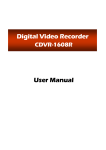
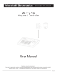
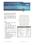
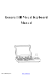
Mobile Digital Video Recorder
CMDVR-0402
User Manual
-1-
IMPORTANT SAFETY INSTRUCTIONS
FCC Compliance Statement
NOTE : This equipment has been tested and found to comply with the limits for a Class A digital
device, pursuant to part 15 of the FCC Rules. These limits are designed to provide reasonable
protection against harmful interference when the equipment is operated in a commercial
environment. This equipment generates, uses, and can radiate radio frequency energy and, if not
installed and used in accordance with the instruction manual, may cause harmful interference to
radio communications. Operation of this equipment in a residential area is likely to cause harmful
interference in which case the user will be required to correct the interference at his own expense.
Safety Instructions
1. Read Instructions
All the safety and operating instructions should be read before the product is operated.
2. Retain Instruction Manuals
The safety and operating instructions should be retained for future reference.
3. Heed Warnings
All warnings on the product and in the operating instructions should be adhered to.
4. Follow Instructions
All operating and use instructions should be followed.
5. Cleaning
Unplug the power cord before cleaning.
Do not use liquid cleaners or aerosol cleaners. Use a damp cloth for cleaning.
6. Attachments
Do not use attachments not recommended by the product manufacturer as they may cause hazards.
7. Water and Moisture
Do no use this product near water.
8. Ventilation
Slots and openings in the cabinet are provided for ventilation and to ensure reliable operation of the
product and to protect it from overheating, and these openings must not be blocked or covered.
9. Power Sources
This product should be operated only from the type of power source indicated on the marking label. If
you are not sure of the type of power supply, consult your product dealer.
10. Safety Check
Upon completion of any service or repairs to this product ask the service technician to perform
safety checks to determine that the product is in proper operating condition.
11. Heat
The product should be situated away from heat sources such as radiators, heat registers, stoves, or
other products (including amplifiers) that produce heat the product.
-2-
CONTENTS
IMPORTANT SAFETY INSTRUCTIONS……………………………………………..………2
INDEX……………………………………………………………………….……………………… 3
1. INTRODUCTION
Package Contents……………………………………………………………………..…… 4
Front Panel…………………………………………………………………………………… 5
Rear Panel……………………………………………………………………………….…….6
Remote Controller……………………………………………………...………………..… 7
2. INSTALLATION
Hard Drive..………….………..………………………………….…….………………….. 8
Connections..………………..………………………………………….…………..……… 9
Starting the DVR………………………………………………………………….………… 10
Log In & Log Out…………………………………………………………………….……… 11
3. CONFIGURATION
System Setup………...……….………………..……………………….....…………..... 12
Camera Setup…………………………………………………..………………………….. 13
Motion Detection……………………..…………………………………………….. 14
Record Setup………………………………………….......…………..………….………..15
16
Record Scheduler……………………………………………………………………………..16
Sensor Setup……………………..…………………………….…………………………… 18
Network Setup…………….…………………………………….………..……………….. 19
Display Setup ……….……………………………………………..………………………. 21
22
Backup & Format………………………….…………………………………………………..21
4. OPERATION
Monitoring……………………………………………………………………………..……….
23
Monitoring Screen…………………………….………………………………....… 23
Freeze…………………………….…………………………….……………....………
23
Zoom………………………….……..………………………….………….……………
23
Sequence Display………….………………………………….…………………….…
24
PTZ Control…..………………………………………………………………………………. 24
Search(Playback)…………………….……………………………….………………………25
DVR Search……………………….……………………………………………………25
USB Memory Search…………………………………………………………….…….
29
LOG(Event) Search………….…………………………………………………..……..…. 29
Video Clip Copy……………………….……………………………………………………. 32
33
Appendix : Technical Specification……………………………………………………………
-3-
1. INTRODUCTION
The CMDVR0402 is a compact sized multiplexer digital video recorder developed specifically
for mobile transportations such as vehicles, buses, trains, etc. Unlike outdated time-lapse
VCRs, the CMDVR0402 provides extremely long recording capabilities with advanced recording
and convenient search functions.
Package Contents
Check the package and contents for visible damage. If any components are damaged or
missing, do not attempt to use the unit, contact the supplier immediately.
If the unit must
be returned, it must be shipped in the original packing box.
CMDVR0401 Unit
DC Power Cable
Remote Controller
HDD Lock Key
User Manual
Network Client Software
-4-
Introduction
Front Panel
13
14
CH1
REMOTE
MENU
PREV
(ENTER)
(PTZ)
(PTZ)
(PTZ)
15
16
CH3
CH2
NEXT
CH4
CH
ESC
(PTZ)
HDD LOCK
2
1
3
4
5
6
9
1 REMOTE SENSOR
ESC
playback.
11 HDD POWER /OPERATION LED
(PTZ)
12 HDD KEY LOCK
Move, decrease values, PTZ Control(Tilt)
13 CH1
(PTZ)
Recording Indicator LED
Move, decrease values, PTZ Control(Pan)
6
12
Change channels during monitoring or
(PTZ)
Move, increase values, PTZ control(Tilt)
5
10 11
10 CH
Enter MENU, Select, Apply values
4
9
Return to previous mode
2 MENU(ENTER)
3
8
7
14 CH2
(PTZ)
Recording Indicator LED
Move, increase values, PTZ control(Pan)
15 CH3
7 PREV
Recording Indicator LED
Move to previous category
16 CH4
8 NEXT
Recording Indicator LED
Move to next category
-5-
Introduction
Rear Panel
V/OUT
V/IN1
V/IN2
V/IN3
V/IN4
TXT/IN REMOTE
A/IN2
USB
9
10
11
DC8V
~36V
12 13
LAN
14
15
1 Audio In 1
9
2 Audio Out 1
10 Text In
3 Audio Out 2
11 USB Port
4 Video Out
12 Remote Eye
5 Video In 1
13 Power Cord
6 Video In 2
14 LAN
7 Video In 3
7
8 Video In 4
-6-
Audio In 2
15 RS485
V
AI1
A/OUT2
AI3
A/OUT1
AI2
A/IN1
AO
8
AI4
7
A0
6
GND
5
GPS
4
PTZ
3
PTZn
2
RS485
1
Introduction
Remote Controller
OSD
OSD On/Off.
AUDIO
Select Audio Channel.
ESC
Return to previous mode.
OSD
AUDIO
ESC
JITTER
CH
STEP-
STEP+
PREV
PLAY
ZOOM+
FF
ID
REC
RW
CH
ID
Move Up, PTZ Control(Tilt), Increase value.
Set ID of remote controller.
MENU
(While
pressing ID button, press 2 digits from
the number buttons and release the ID button).
Identical
ID must be applied for the DVR and
ENTER
NEXT
Remote controller.
OSD
AUDIO
REC
CH
ENTER
SLOW
Change channels during monitoring or playback.
FOCUS+
1
2
3
MENU(ENTER)
CH2
CH3
6
7
8
SEQUENCE
+(SKIP)
PREV(ZOOM+)
4
5
REFRESH
CH4
Jump 5 min. during Playback. Frame Advance
during
Pause.
Change
speed
during
SAVE
FULL SCR
Slow/FF/RW.
Jump 5 min. during Playback. Frame Advance
during
Pause.
Change
speed
during
Slow/FF/RW.
Move to previous category. Zoom-In.
Move to next category. Zoom-Out.
Fast Forward Playback.
Pause playback.
Playback in slow motion.
1~4(CH1~CH4)
Number/symbol buttons or select channels 1~4.
5(QUAD)
Number/Letter
button
or
change
to
multi-
display.
6(FREEZE)
Number/Letter button or freeze video during
monitoring mode.
7(SEQUENCE)
Number/Letter
button
or
select
sequence
display during monitoring mode.
8(JITTER)
Number/Letter button or Remove video jitter
during pause..
9(CAPTURE)
Number/Letter button or capture video during
playback.
0(FULL SCR)
NEXT
ZOOM-
Number/symbol buttons or change to full screen
display.
-7-
@:/
ABC
FOCUS+
DEF
GHI
FOCUSJKL
1
2
3
4
5
CH1
CH2
CH3
CH4
QUAD
MNO
PQRS
TUV
WXYZ
.,?!
6
7
8
9
0
FREEZE SEQUENCE JITTER
Toggle between Forward/Reverse Play.
(FOCUS-)
PREV
ZOOM+
QUAD
Fast reverse playback.
(FOCUS+)
┗ SKIP ┛
Move
Right,
PTZ Control(Pan), Increase Value.
9
0
Move Down, PTZ Control(Tilt), Decrease Value.
NEXT(ZOOM-)
+
FOCUS+
Move Left, PTZ Control(Pan), Decrease Value.
Bring up Menu, Select, Apply Changes.
CH1
-(SKIP)
FREEZE
MENU
Record On/Off.
ZOOMPAUSE
ID
ESC
CAPTURE FULL SCR
2. INSTALLATION
Hard Drive
Removable HDD Tray
Screws
HDD Bracket
2.5” HDD
HDD Bracket
Screws
2. Detach the HDD Bracket from the
Tray and attach the 2.5” HDD onto
the Bracket with the supplied
screws.
1. Detach the Removable HDD Tray
from the DVR.
Auxiliary PCB
Screw
Screws
Screws
3. Insert the HDD Bracket into the Tray
and connect the 2.5”HDD to the
Auxiliary PCB. Then fix the Auxiliary
onto the Bracket with the supplied
screws.
4. Attach the Bracket onto the Tray by
using the supplied screws and insert
the Tray into the DVR HDD slot.
※ NOTE
1. To separate HDD from DVR, make sure that you disconnect power cable in stop mode. If you disconnect it
during recording the HDD sector will be damaged. Rotating the HDD Lock Key during recording will
also result in HDD sector damage.
2. “NO HDD” message appears on screen.
The HDD is not connected correctly. In this case, disconnect power cable first and check whether the HDD
has been connected correctly.
-8-
Installation
Connections
A/IN1
A/IN2
A/OUT1
A/OUT2
TXT/IN REMOTE
USB
Audio In
USB
Text In
Video In
Video Out
V/OUT2
V/IN1
DC8V
~36V
LAN
Power
LAN
V/IN2
V/IN3
V/IN4
RS485
Audio Out
RS485
Remote
Controller
-9-
Alarm In 1
Alarm In 2
Alarm In 3
Alarm In 4
Alarm Out 2
Alarm Out 1
Ground
GPS
PTZ
PTZn
Connecting to RS485
Installation
Starting The DVR
After installing the hard disk, connect the power cord to start the DVR.
※ The HDD Lock in the front panel must be in the lock position before turning on the
DVR power.
When starting the DVR for the first time, formatting of the hard disk will commence automatically and
the DVR will be initialized as follows.
The DVR will perform “S.M.A.R.T.” check of the installed hard disk as shown in the above figures.
- The first Line indicates the version of the DVR software.
- The second line indicates the MAC address.
- The third line indicates the hard disk information(Model name, whether or not it is formatted(FAT32)
or not(NOT FAT32), HDD capacity, and S.M.A.R.T. check result.
If no problem is detected [S.M.A.R.T. PASS] will be indicated and if problem is detected [S.M.A.R.T.
FAILURE] will be indicated and a warning will appear on the monitoring screen every 1 minute for a
duration of 5 seconds.
The hard disk capacity indicated may be smaller than the capacity declared by the hard disk producer.
This difference may occur due to the difference in measure units and therefore is not a defect.
If the hard disk detected has not been formatted, recording will start after the formatting is completed.
※ S.M.A.R.T. (Self Monitoring, Analysis and Reporting Technology)
S.M.A.R.T. is a reliability prediction technology to anticipate the failure of a hard disk drive with sufficient
notice to allow a system or user to back up data prior to a drive’s failure.
If the controller detects problems in the disk drive reliability, it will release a warning to the user. In such a
case, the use of the disk drive should be stopped immediately and have it examined.
- 10 -
Installation
Log In & Log Out
The USER will be required to Log In(Type in the PASSWORD) in order to enter Setup,
Search(Playback), PTZ Control, and Log Search.
※ Default PASSWORD is set at “0000”
1) Using the Remote Controller press the [ENTER] button and use the Number buttons to type in
the password. You may use the [Left] button for backspace.
2) After typing in the Password, press the [ENTER] button. Re-type the correct Password if the
following message appears on the screen.
3) You may now enter the Menu Screen by pressing [ENTER], or press the PTZ, SEARCH, LOG,
SETUP buttons to enter each functions.
※ LOG OUT
Press [ENTER] to enter the Menu Window and select LOGOUT.
This will prohibit any other users other than the authorized personnel with proper password to
enter SETUP, SEARCH, PTZ Control,and LOG.
※ Password can be changed in the SETUP - SYSTEM menu.
- 11 -
3. CONFIGURATION
Before starting your DVR for the first time, you should establish the initial settings. This includes
categories such as time and date, display language, camera, audio, remote control, record mode,
network and password.
Press the [MENU] button on the Remote Controller or the DVR front panel to enter the MAIN MENU and
select [SETUP].
The selected category will be indicated in a different color as shown in the above figure.
Use the [Up, Down] buttons to move to the desired category and press the [ENTER] button to enter the
selected category.
Press [ESC] button to return to the Monitoring Mode.
※ OPERATION
PREV : Select Previous category(Up)
NEXT : Select Next category(Down)
ESC : Return to previous mode
ENTER : Apply the new setting values and move to the next category.
For entering numeric and letter values, the user may use the 10 keys on the remote control.
※ Caution
Recording will stop when Date/Time is changed, Formatting occurs and restart recording automatically after
initializing the DVR system.
- 12 -
Configuration
System Setup
CATEGORY
LANGUAGE
DEFAULT
ENGLISH
ADJUSTMENT
Change the OSD LANGUAGE.
[Up, Down][Left, Right]: ENGLISH Ù CHINESE Ù KOREAN Ù JAPANESE
[ENTER] : Apply new LANGUAGE.
Set the ID(Identification no.) of DVR.(Limit : 0~255)
ID
0
[Left, Down] : Decrease number
[Right, Up] : Increase number
Select [ADMIN] and press [ENTER] to change the PASSWORD.
PASSWORD
CHANGE
[Up, Down, Left, Right] : Change ADMIN Ù USER1 Ù USER2
0000
[ENTER] : Enter PASSWORD window
[Up, Down] : Select letter, number, symbol
[ENTER] : Apply new PASSWORD
Select DATE indication method.(YY-MM-DD, MM-DD-YY, DD-MM-YY.)
[Up, Down][Left, Right] : Move between YY-MM-DD, MM-DD-YY, DD-MM-YY
[ENTER] : Apply and move to DATE
DATE/TIME
Current
Date/Time
Change DATE/TIME
[Left, Right] : Move between Year/Month/Day or Hour/Min./Sec.
[Up, Down] : Increase/Decrease the DATE/TIME.
[ENTER] : Apply and move to DST
※ System check will be performed when TIME is changed.
DST
NO
Set the DAYLIGHT SAVING TIME.
[Up ,Down], [Left, Right] : UseÙNot Use
Copy the SETUP values from the “/DVRSYS/” folder of the DVR to a USB memory
SETUP
IM/EXPORT
stick or from a USB memory stick to the DVR.
[Up, Down][Left, Right] : IMPORTÙEXPORT.
[ENTER] : Perform IMPORT/EXPORT
Upgrade the Firmware of the System.
SYSTEM
UPGRADE
Copy the Firmware file “/DVRSYS/FW/FDVR0402.BIN” to a USB memory stick and
connect the USB memory stick to the DVR..
The DVR will reboot in order to apply the UPGRADE.
[ENTER] : Perform UPGRADE.
HDD
Indicate the HDD’s total capacity, current memory status, and S.M.A.R.T.
STATUS
information.
COLOR
SYSTEM
Select NTSC or PAL system.
[ENTER] : Toggle to change between NTSCÙPAL.
- 13 -
Configuration
CATEGORY
DEFAULT
ADJUSTMENT
The date of the DVR Firmware Version will be indicated.
S/W
All setting values will return to its’ initial FACTORY DEFAULT values.
FACTORY
[Up, Down][Left, Right]: Toggle between YESÙNO
RESET
[ENTER] : Apply/Not Apply the initial DEFAULT Values.
※ Password input will be required.
Camera Setup
CATEGORY
DEFAULT
Set whether to hide the selected channel or channels from the live monitoring
screen while continuing to record the channels.
[ENTER] : Toggle to Apply/Not Apply.
COVERT
CHANNEL
NAME
ADJUSTMENT
1
CH1
Select the channel that is to be configured.
[Up, Down][Left, Right] : Change channels
[CH] and Numeral keys can also be used to change the channel.
Assign an Identification NAME for the cameras.
Input Range : Max. 8 characters(Combination of Number/Letter/ Symbol)
[Left, Right] : Move to previous or next space.
[Up, Down] : Select letter, number, symbol.
Numeral/Letter/Symbol keys can also be used to input the Name.
Set HUE level(Limit : 0~255)
HUE
5
[Left, Down] : Decrease level
[Right, Up] : Increase level
Number keys can also be used to change the Hue level.
Set CONTRAST level(Limit : 0~255)
CONTRAST
5
[Left, Down] : Decrease level
[Right, Up] : Increase level
Number keys can also be used to change the Contrast level.
Set BRIGHTNESS level(Limit : 0~255)
BRIGHTNESS
5
[Left, Down] : Decrease level
[Right, Up] : Increase level
Number keys can also be used to change the Brightness level.
Set the PTZ ID.(Limit : 0~255)
PTZ ID
[Left, Down] : Decrease number
[Right, Up] : Increase number
Number keys can also be used to change the PTZ ID.
- 14 -
Configuration
CATEGORY
DEFAULT
ADJUSTMENT
Select the PTZ Driver.
[Up, Down, Right, Left] : Select the PTZ Driver
PTZ DRIVER
NONE
< Compatible PTZ DRIVER List >
Pelco_D, Pelco_P, Panasonic, PT_A100L, DOME1, DOME2, HSDN_251N,
WPT_101, SJ_2819, SK_2162D, DSC_230, GROOM_D106, CAZ1723, VC_C4,
SCC_C4201, CRR1600T, SRX_100B, VVK_3000, ORX_1000, NK97CH, PIH717,
PIH718, Vicon, Hangang, Gateway, E_DSO, Ateye, GRX_1000A, AD, JO308ACU,
Sensormatic, Smartscan, Sungjin
Set up Baud Rate, Data Bit, Parity, Stop Bit values.
[ENTER] : Enter the PTZ Configuration Menu.
Press [ENTER] to TEST.
[Left, Down] : Decrease Rate/Bit/Parity
[Right, Up] : Increase Rate/Bit/Parity
PARITY : NON, ODD, EVEN.
PTZ Setting
Set the SENSITIVITY level(Limit : 0(Low)~100(High))
SENSITIVITY
80
[Left, Down] : Decrease level
[Right, Up] : Increase level
Number keys can also be used to change the Sensitivity level.
Select Motion Detection Area.
MOTION
[Up, Down, Right, Left] : Move position
[ENTER] : Toggle between Able Ù Cancel
MOTION DETECTION AREA
The area selected for motion detection will be indicated in pink as shown below.
- 15 -
Configuration
Recording Setup
CATEGORY
DEFAULT
NTSC
352X240
RESOLUTION
PAL
352X288
ADJUSTMENT
Set the recording resolution level.
Even if QUAD recording is selected, only 1 channel will be recorded if the
resolution is set at 720x480. Therefore, when 720x480 is set, designate which
channel to be recorded.
4 channels can only be recorded if the resolution is set at 352x240.
[Left, Right] : Move between resolution and channel(When 720x480 is
selected).
[Up, Down] : Change resolution(Change channel if resolution is set at
720x480)
AUDIO REC
ALL
USE
[Up, Right][Down, Left] : Move between ALL Ù NO Ù 1 Ù 2 Ù ALL…..
Select whether to record/display Text Overlay on all channels.
TEXT OVERLAY
WATERMARK
Set the AUDIO recording channel
[Up, Right][Down, Left] : Move between None Ù GPS Ù Speed Gun Ù POS
NO
Set whether to use the WATERMARK.
[Up, Right][Down, Left] : YESÙNO
Set the WATERMARK KEY value.
WATERMARK
KEY
0
[Left, Down] : Decrease value
[Right, Up] : Increase value
Limit : 0~15
Set the WATERMARK STRENGTH.
WATERMARK
STRENGTH
0
[Left, Down] : Decrease level
[Right, Up] : Increase level
Limit : 0~4
CHANNEL
1, 2
Recording FPS and Quality can be set only in groups of 2 channels.
Group 1 : Channel 1 & 2
Group 2 : Channel 3 & 4
[Left, Down][Right, Up] : Move between two groups.
Set the FPS(frame per second).
FPS
NTSC: 15
PAL : 12
NTSC(fps) : 0, 1, 2, 3, 4, 5, 6, 7, 10, 15, 30
PAL(fps)
: 0, 1, 2, 3, 4, 5, 6, 8, 12, 25
[Left, Down] : Decrease FPS level
[Right, Up] : Increase FPS level
Set video recording QUALITY
QUALITY
MIDDLE
LOW Ù MIDDLE Ù HIGH Ù SUPER
[Left, Down][Right, Up] : Move between quality levels.
END OF DISK
OVERWRITE
Set whether to OVERWRITE or STOP recording when the installed HDD is full.
- 16 -
Configuration
Record Schedule
The recording time can be set according to Channels, Weekday, and Time.
CATEGORY
WEEKDAY
DEFAULT
SUN
ADJUSTMENTS
Select the WEEKDAY Scheduling.
[Up, Down] : Change WEEKDAY
Set the Recording method.
C : Continuous
M : Motion
D : Dual Mode (Motion + Sensor)
SCHEDULE TABLE
C
S : Sensor
X : No recording
[NEXT, PREVIOUS] : Move between Weekday and Time Table
[Up, Down, Left, Right] : Move to select Channel & Time
[ENTER] : C Ù M Ù D Ù S Ù X Ù C Ù….
Select ALL and apply the same recording method for the whole day.
- 17 -
Configuration
Sensor Setup
CATEGORY
SENSOR
NO.
SENSOR
TYPE
DEFAULT
ADJUSTMENT
Set the SENSOR Number.
1
[Left, Down] : Decrease Number
[Right, Up] : Increase Number
NO
Select the SENSOR TYPE
[Up, Down, Left, Right] : Select NO or NC
Select the CAMERA that is to be connected to the SENSOR
CAMERA
[Left, Down, Right, Up] : Move between channels
LINK
[ENTER] : Toggle to Enable/Disable
Select the ALARM OUTPUT that will be connected to the SENSOR
ALARM
[Left, Down, Right, Up] : Move between channels
LINK
[ENTER] : Toggle to Enable/Disable
Set the OPERATION TIME for the selected sensor.
(Start Hour ~ End Hour)
OPERATION
TIME
It will not activate if same time is set.
0~24
Range : 0~24(Hour)
[Left, Right] : Move between Start Ù End
[Up, Down] : Increase/Decrease hour.
Number keys can also be used to change the hour.
Set whether to show the camera view in full screen mode when the sensor is
triggered.
OPERATION
MODE
SPOT
[NORMAL] : Disable,
[SPOT] : Apply
If a sensor is linked to several channels, the channels will be displayed in multiscreen mode.
[Up, Down, Left, Right]: Move between NORMALÙSPOT
Set the time duration for which the camera will continue recording when the
sensor is triggered.
RECORDING
DWELL TIME
30
Duration range : 0~600(Second)
[Left, Down] : Decrease duration
[Right, Up] : Increase duration
Number keys can also be used to change the dwell time.
Set the duration for which the Alarm(Output) will continue after the sensor is
triggered.
OUTPUT
DWELL TIME
30
Duration range : 0~600(Second)
[Left, Down] : Decrease duration
[Right, Up] : Increase duration
Number keys can also be used to change the dwell time.
BEEP
ON
Set whether to use the DVR Buzzer when a sensor is triggered.
[ENTER] : Toggle Enable/Disable
- 18 -
Configuration
Network Setup
CATEGORY
DEFAULT
ADJUSTMENT
Set the DVR NAME.
Use the Numeral/Letter/Symbol buttons or the [Up, Down] buttons to input
the Name.
[Left, Right] : Move to previous, next space
NAME
[Up, Down] : Select letter, number, symbol
TYPE
FIXED
Select IP Type.
[Up, Down][Left, Right]: Select AUTO Ù FIXED Ùr PPPOE
Set the PORT number that will be connected to the Network.
Range : 0~65535
PORT
[Left, Down] : Decrease number
[Right, UP] : Increase number
Number keys can also be used to change the Port number.
Set the IP Address of the DVR.
IP
[Left, Right] : Move to next number field
[Up, Down] : Increase/Decrease number
Number keys can also be used to change the IP number.
Set the GATEWAY Address of the DVR.
GATEWAY
[Left, Right] : Move to next number field
[Up, Down] : Increase/Decrease number
Number keys can also be used to change the Gateway address
Set the SUBNET MASK Number of the DVR.
SUBNET
[Left, Right] : Move to next number field
[Up, Down] : Increase/Decrease number
Number keys can also be used to change the Subnet number.
Set the DNS Address.
DNS
[Left, Right] : Move to next number field
[Up, Down] : Increase/Decrease number
Number keys can also be used to change the DNS address.
Set the SMTP Address.
SMTP
[Left, Right] : Move to next number field
[Up, Down] : Increase/Decrease number
Number keys can also be used to change the STMP address.
MAC
Display the MAC Address of the DVR.
MAC Address is pre-set during production and cannot be changed.
- 19 -
Configuration
CATEGORY
DEFAULT
ADJUSTMENT
Set the PPPOE ID for internet connection when using ADSL modems.
[Up, Down] : Select letter, number, symbol.
PPPOE ID
[Left, Right] : Move to next space
Numeral/Letter/Symbol keys can also be used to change the ID
Limit: 16 characters(Combination of numbers and letters).
Set the PPPOE PASSWORD for internet connection when using ADSL modems.
PPPOE
[Up, Down] : Select letter, number, symbol.
PASSWORD
[Left, Right] : Move to next space
Numeral/Letter/Symbol keys can also be used to change the Password
Limit: 16 characters(Combination of numbers and letters).
CATEGORY
E-MAIL
AUTHORITY
DEFAULT
ADJUSTMENT
NO
Set whether E-Mail Login is required for E-MAIL notification when a sensor is
triggered
[Up, Down][Left, Right] : Select YES or NO
Set the E-Mail Login ID
[Up, Down] : Select letter, number, symbol.
AUTH- ID
[Left, Right] : Move to next space
Numeral/Letter/Symbol keys can also be used to change the ID
Limit : 16 characters(Combination of numbers and letters).
Set the E-Mail Login Password.
[Up, Down] : Select letter, number, symbol.
AUTH-PASS
[Left, Right] : Move to next space
Numeral/Letter/Symbol keys can also be used to change the Password.
Limit : 16 characters(Combination of numbers and letters).
Enter the E-MAIL address of the SENDER
[Up, Down] : Select letter, number, symbol.
E-MAIL FROM
[Left, Right] : Move to next space
Numeral/Letter/Symbol keys can also be used to input the Address
Limit: 50 characters.
Enter the E-MAIL address of the RECEIVER.
[Up, Down] : Select letter, number, symbol.
E-MAIL TO
[Left, Right] : Move to next space
Numeral/Letter/Symbol keys can also be used to input the Address
Limit : 50 characters.
Select EVENTS for automatic transmission of e-mail notifications
EVENT MAIL
[Up, Down, Left, Right] : Move between the Events.
[ENTER] : Toggle to Enable/Disable
- 20 -
Configuration
Display Setup
CATEGORY
DEFAULT
ADJUSTMENT
OSD(On Screen Display)
Designate which information to be shown on the monitoring screen.
OSD
ALL
[Left, Up] : Move to upper information
[Right, Down] : Move to lower information
[ENTER] : Toggle to Apply/Disable
Set the BORDER COLOR of screen
BORDER
COLOR
GRAY2
[Left, Up] : Move to upper category.
[Right, Down] : Move to lower category.
[ENTER] : Toggle to Apply/Disable
Set the SEQUENCE DWELL TIME of the monitoring channels
SEQUENCE
DWELL TIME
Range : 1~60(Second)
5
[Left, Down] : Decrease number
[Right, UP] : Increase number
Number keys can also be used to change the dwell time
When viewing video in the progressive(VGA) scan mode the interlaced image is
transformed to the progressive image,
VGA
DEINTERLACING
and if there is moving images, horizontal Lines(Tearing) will appear on the
BOB
screen. Selecting BOB will make the tearing disappear and if there is no moving
images selecting WEAVE will provide a clearer image.
[Up, Down, Left, Right] : Select between BOB Ù WEAVE
[ENTER] : Apply and move to next category.
- 21 -
Configuration
Backup & Format
CATEGORY
ADJUSTMENT
Set the START-END TIME of a recorded video for Backup
[Left, Right] : Move between Year/Month/Day/Time
BACKUP
[Up, Down] : Increase/Decrease number
Number keys can also be used to change date & time
Select the backup memory device.
Move to START and press [ENTER].
Format the internal HDD or External Memory
FORMAT
[Left, Right] : Move between the memory drives.
Select the memory to be formatted and activate START
※ Recording will stop during formatting.
- 22 -
4. OPERATION
Monitoring
Monitoring Screen
The video signals received by the CMDVR0402 can be
viewed on Multi-Screens or the image can be viewed in
the Pause and Zoom mode.
Date, Time, Camera Number, Recording Status, HDD
Capacity Usage are displayed on the screen.
Information displayed on the screen(OSD) can be
Changed by pressing the [OSD] button.
FREEZE
FREEZE is a function to view still frames during
monitoring mode. (Recording will continue).
Press the [FREEZE] button for still frame viewing.
Press the button again to resume monitoring. During
Freeze mode, Letter “F” will appear in the center of
the screen.
ZOOM
ZOOM mode allows 200% magnification of the selected
area of the screen.
Press the [ZOOM] button and the magnification area
will appear on the center of the screen.
The magnification area can be moved horizontally and
vertically by pressing the [Up, Down, Left, Right] buttons.
Pressing the [Enter] button each time will magnify/
de-magnify the selected area.
Press the [ESC] button to escape from ZOOM mode.
- 23 -
Operation
SEQUENCE DISPLAY
Single screen sequence display is possible by pressing the [SEQUENCE] button.
The Sequence Dwell Time can be set in the [SETUP] – [DISPLAY] menu.
icon will appear on the screen during the sequence display mode.
PTZ Control
This is a mode to control Camera Direction/Focus/Zoom/Preset/Swing/Pattern/Group during the
Monitoring Mode.
Press the [PTZ] button from the Monitoring Mode or press [MENU] and select PTZ.
The window showing the PTZ control status will appear on the bottom of the screen
CATEGORY
CHANNEL
PAN / TILT
OPERATION
Select the channel you wish to control.
[CH] : Change channels
[Left, Up] : Move camera up and down.
[Right, Down] : Move camera left and right.
ZOOM
Use ZOOM buttons to zoom in/out.
FOCUS
Use the FOCUS buttons to focus in/out.
APERTURE
Use the IRIS buttons to adjust the aperture.
For Preset/Swing/Pattern/Group/Setting press [ENTER] after selecting the channel
Enter the Setting mode of the PTZ to set the Preset/Swing/Pattern/Group movement of the PTZ Camera.
※ Please refer to the Operation Manual of the PTZ camera to setup the PRESET, SWING,
PATTERN, GROUP configurations.
- 24 -
Operation
SEARCH (Playback)
You may search the recorded contents of the DVR by using the Time Search Mode.
Enter the [SEARCH] menu and the following screen will appear.
Select either “DVR” or “USB”(Highlighted with yellow stripe when selected) with the [Up, Down]
buttons and press [ENTER].
DVR Search : TIME & DATE SEARCH
The following Time & Date Search Mode will appear on the screen.
①
④
②
⑤
③
① YEAR - MONTH
② DAY
③ Hour/Channel Table
The recording information will be shown on an Hour and Channel(camera) Table for the selected Day.
④ Recording Information
The recording information of the selected Year, Month, Day, Hour will be shown as “Minute: Second
~ Minute: Second”.
⑤ Playback Information
1) Audio Channel
The audio channel status will be indicated as follows..
(AUDIO OFF) ,
(AUDIO 1 ON),
(AUDIO 2 ON)
2) Multi-Screen Display mode
The multi-screen display mode will be indicated as follows.
: CH1,
: CH2,
: CH3,
: CH4,
: 4 Split-screen mode
- 25 -
Operation
SEARCH PROCEDURE
By selecting the [SEARCH] menu, information of the first file recorded on the current day will appear on
the screen. And the search procedure will start from the “Day” indication field.
1) Select the Year and Month.
On the calendar, days containing recorded data will be highlighted in yellow.
Button
Function
Left, Right
Move between Year Ù Month
Up, Down
Change the Year and Month
ENTER, NEXT
Move to the Day indication field
PREV
PREV : Move to the Hour/Channel indication table
2) Select the Day.
- 26 -
Operation
Move to the relevant Day and the recording information for the corresponding Day will be
indicated on the Hour/Channel indication table.
Button
Function
Up, Down, Left,
Right
Move to the desired Day
ENTER
Move to the Hour/Channel indication table
PREV, NEXT
PREV : Move to “Year-Month” indication field
NEXT : Move to the Hour/Channel indication table
3) Select the relevant Hour/Channel.
The relevant recording information will appear on the upper left corner of the screen for the
selected Hour/Channel.
Button
Function
Left, Right
Move to relevant hour
Up, Down
Move to relevant Channel (CH1 ~ CH4, QUAD Button)
ENTER
Move to Time Range Selection
PREV, NEXT
PREV : Move to Day indication field
NEXT : Move to Record information field (If data exist)
- 27 -
Operation
4) Select the relevant Time Range and press [Enter] button to play the recording.
Button
Function
Up, Down
Move from file to file(Time range)
ENTER
Start playback
PREV, NEXT
PREV : Move to Hour/Channel indication table
NEXT : Move to “Year-Month” indicator
FULL SCREEN DISPLAY
The playback screen can be changed to the full screen
mode by pressing the [FULL SCR] button.
Playback Information will appear on the lower part of
the screen.
Press the [OSD] button to make the Playback
Information disappear or appear.
Press the [FULL SCR] button again to return to the Time
& Date Search mode.
< Playback Information >
Time Indicator
Date Indicator
Playback Information
- 28 -
Audio/Display Status
Operation
USB Search
Data saved on a USB Memory Stick may be played back by following the USB Search procedure.
Select the [SEARCH] menu and move to “USB” by using the [Up, Down] buttons. Then press
the [ENTER] button to enter the USB Time Search Mode.
SEARCH PROCEDURE
The following display will appear on the screen.
Video data stored in the USB will appear according to the
recording dates.
Select the date you wish to search by using the [Up, Down]
buttons and press [ENTER].
If data exists for the selected date, the following time
display will appear on the screen.
Select the relevant time and press [ENTER] to start
playback.
The playback will proceed in the Full Screen Mode.
LOG (Event) Search
All events that occur on the DVR are recorded in the LOG.
Select the [LOG] Menu and the following LOG Time Search mode will appear.
①
②
- 29 -
Operation
① SORT
Selection of LOG types.
Type
Explanations
POWER
Power On/Off
SENSOR
Sensor Input
RECORD
Record Start/Stop
CAMERA
Camera Input Signal data
NETWORK
Network connections
BACKUP
Start Backup
SETUP
Setup Enter/Exit/Save
CLOCK
Date/Time adjustments
② LOG LIST
List of SORT categories of the selected date.
SEARCH PROCEDURE
1) Select the relevant “Year, Month”.
On the calendar, days containing LOG records will be highlighted in yellow.
Button
Function
Left, Right
Toggle between Year Ù Month
Up, Down
Select the relevant Year and Month
ENTER
Move to the Day indication field
PREV, NEXT
PREV : Move to LOG List(If log records exist for the selected date.)
NEXT : Move to Day indication field
- 30 -
Operation
2) Select the desired Day.
Move to the desired Day, then the corresponding log records of the selected Day will appear in
the LOG List at the bottom of the screen
Button
Function
Up, Down,
Left, Right
Move to relevant Day
ENTER
Move to LOG List
PREV, NEXT
PREV : Move to “Year-Month” indication field
NEXT : Move to SORT
3) SORT
Select the desired type of log information of the selected Day.
- 31 -
Operation
Button
Function
Up, Down
Select the SORT category.
(Select among ALL, POWER, SENSOR, RECORD, CAMERA, LAN,
BACKUP, SETUP, TIME.)
ENTER
Move to LOG List(If log records exist for the selected date.)
PREV, NEXT
PREV : Move to Day indication field
NEXT : Move to LOG List(If log records exist for the selected date.)
4) Event Playback
Video recordings activated by Alarm Inputs are listed in the LOG List(SENSOR) and the
recordings can be played back by selecting “SENSOR ON” from the list and pressing the [ENTER]
button. (If recorded data exists)
VIDEO CLIP COPY
Video Clip copies of recorded video datas can be made to a USB Memory Stick by taking following the
steps.
COPY PROCEDURE
1. Enter SEARCH(DVR).
2. Follow the procedure explained in DVR SEARCH to find the relevant video data and activate playback.
3. Find the Starting location of the video clip you wish to make a copy and press the [CAPTURE] button
to designate the Starting location. The video will be put on pause and you will be required to select
the external memory device on which the copy will be made.
※ The free memory space of the external memory device and the file size of the video clip will be
indicated on the screen.
The free memory space of the external memory device must be larger
than the video clip file size in order to make a copy.
4. Use the Play, Fast Forward/Reverse, Slow Motion, Skip buttons to find the end of the video clip you
wish to copy and press the [CAPTURE] button to designate the End location.
5. Copying will proceed and the copy progress rate will be indicated on the screen.
※ The [CAPTURE] button can only be used during playback.
※ You may return to the monitoring mode during the copying process by pressing the [ESC]
button.
- 32 -
Appendix
Technical Specification
Category
Specification
Operating System
Embedded Proprietary OS
Compression Algorithm
MPEG4(VIDEO) , ADPCM(SOUND)
Multi-Screen Display
1/4/Sequence
Video Input
4 BNC
Monitor Output
1 Composite
Display Speed
120fps
Recording Resolution
352x240, 720x480(NTSC), 352x288, 720x576(PAL)
Recording Speed(CIF)
Max 120fps(NTSC), Max 100fps(PAL)
Recording Mode
Continuous, Timelapse, Schedule, Event
Audio
2 Line-In / 2 Line-Out
Search Method
Time & Date, Event
Sensor Alarm
4 Alarm Input(NO/NC) / 1 Alarm Output
Network Interface
RJ-45
PTZ Interface
RS-485
Storage
1 Swappabe 3.5”HDD(2.5” Option)
Control
Front Panel, Remote Controller
Special Features
Motion Detection, Event Log, Text Overlay of Vehicle/
GPS/Speed-Gun Information
Network Monitoring
Remote Access Software
Verification
Digital Watermark
Vibration Absorption
Internal Shock Proof Cradle
Operating Temperature and Humidity
-4℉~140℉ / 20~90%RH
Storage Temperature and Humidity
41℉~104℉ / 20~80%RH
Weight
3.5kg
Dimension(W x H x D)
178mm x 82mm x 275mm
Power Supply
DC 8V~36V
- 33 -