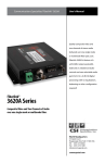
1
Communications Specialties’ Fiberlink® 4040
User’s Manual
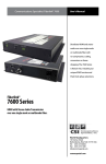
The Fiberlink® 4040 Series is a
configurable, adjustment-free
transmitter/receiver pair that
employs digital processing and
transmission techniques to
convey up to four 1-way channels
of audio.
Fiberlink®
4040 Series
Four channels of audio over one
single mode or multimode fiber.
World Headquarters
125 Comac Street
Ronkonkoma, New York 11779 USA
Tel: (631) 273-0404
Fax: (631) 273-1638
[email protected]
commspecial.com
Fiberlink® 4040 Series
Contents
Contents
Welcome . . . . . . . . . . . . . . . . . . . . . . . . . . . . . . . . . . . . . . . . . . . . . . . . . . . . . . . . . . . . . . . . . . 3
Features. . . . . . . . . . . . . . . . . . . . . . . . . . . . . . . . . . . . . . . . . . . . . . . . . . . . . . . . . . . . . . . . . . . 3
Package Contents. . . . . . . . . . . . . . . . . . . . . . . . . . . . . . . . . . . . . . . . . . . . . . . . . . . . . . . . . . 3
Technical Specifications
Model Part Number Specifications. . . . . . . . . . . . . . . . . . . . . . . . . . . . . . . . . . . . . 4
General Specifications. . . . . . . . . . . . . . . . . . . . . . . . . . . . . . . . . . . . . . . . . . . . . . . . . 4
Installation Instructions. . . . . . . . . . . . . . . . . . . . . . . . . . . . . . . . . . . . . . . . . . . . . . . . . . . . 6
Audio Switch Settings & Options . . . . . . . . . . . . . . . . . . . . . . . . . . . . . . . . . . . . . . . . . . . 7
System Terminal Block Connections . . . . . . . . . . . . . . . . . . . . . . . . . . . . . . . . . . . . . . . . 8
Indicator LEDs . . . . . . . . . . . . . . . . . . . . . . . . . . . . . . . . . . . . . . . . . . . . . . . . . . . . . . . . . . . . . 9
Operating Pointers. . . . . . . . . . . . . . . . . . . . . . . . . . . . . . . . . . . . . . . . . . . . . . . . . . . . . . . 10
Troubleshooting. . . . . . . . . . . . . . . . . . . . . . . . . . . . . . . . . . . . . . . . . . . . . . . . . . . . . . . . . 10
Maintenance and Repairs . . . . . . . . . . . . . . . . . . . . . . . . . . . . . . . . . . . . . . . . . . . . . . . . 11
Certifications . . . . . . . . . . . . . . . . . . . . . . . . . . . . . . . . . . . . . . . . . . . . . . . . . . . . . . . . . . . . 11
Warranty . . . . . . . . . . . . . . . . . . . . . . . . . . . . . . . . . . . . . . . . . . . . . . . . . . . . . . . . . . . . . . . . 12
Accessories and Related Products . . . . . . . . . . . . . . . . . . . . . . . . . . . . . . . . . . . . . . . . 13
Page 2
Fiberlink® 4040 Series User’s Manual
Fiberlink® 4040 Series
Welcome | Features | Package Contents
Welcome
The Fiberlink® 4040 series optical transmission system is a configurable, adjustment-free
transmitter/receiver pair that employs digital processing and transmission techniques to
convey up to four 1-way channels of audio.
The use of digital encoding assures high-quality noise-free transmissions that retain all of
their initial parameters regardless of fiber optic cable attenuation. In addition, integral LED
indicators are provided on each unit to continuously signify the presence of audio signals
and, thus, the proper operation of each side of the system. .
Features
•Transmits over one multimode or single mode fiber at 850, 1310 or 1550 nm
•No adjustments; pure digital processing and transmission
•24 bit/96 kHz sampling; maximum audio level +24 dBu
•20 Hz to 20 kHz frequency response
•Line level, balanced or unbalanced audio operation
•Indicator LEDs monitor audio signals and power
•Wide range power supply allows operation from low voltage AC and DC sources
•Card version fills one slot in 6000A card cage
•System consists of transmitter and receiver unit; card or box version.
•RoHS Compliant
Package Contents
•One Fiberlink® 4040 or 4041
•This User’s Manual
Fiberlink® 4040 Series User’s Manual
Page 3
Fiberlink® 4040 Series
Technical Specifications
Technical Specifications
Model Part Number Specification
Unit Type
Transmitter Box
Transmitter Rack Card
Receiver Box
Receiver Rack Card
(x)
(y)
Part Number
4040-Bxy
4040-Cxy
4041-Bxy
4041-Cxy
1 - 850nm Multimode
3 - 1310nm Multimode
7 - 1310nm Single Mode
9 - 1510nm Single Mode
F - FCPC Connector
S - ST Connector
General Specifications
LED Indicators
Power Requirements*
Operating Temperature Range
Relative Humidity
Optical Connectors
Operating Wavelength
Physical Size
Weight
Slots Filled in 6000A Card Cage
MTBF
Power; Audio Present (per channel);
Alarm LED (card version only)
9-24 volts AC or DC, 5 watts
-35o to +60o C
10%-90% (non-condensing)
ST or FCPC
850, 1310 or 1550 nm
6.5 W x 1.15 H x 8 L (inches)
165 W x 29 H x 203 L (mm)
approx. 1 lb.; 0.45 kg
1
83,000 Hours
* For operation from 95-250VAC, 50/60Hz, a PDPS-1 plug-in adapter is required.
Page 4
Fiberlink® 4040 Series User’s Manual
Technical Specifications
Fiberlink® 4040 Series
Technical Specifications
Audio Specifications:
Number of Audio Channels
Frequency Response
Bits-per-Sample/Sampling Rate
Maximum Audio Level
SNR (A-Weighted)
THD+N
Channel Phase Differential
System Latency
Crosstalk
Input Impedance
Output Impedance
Audio Connectors
Switches
4, balanced or unbalanced
+0/-0.5 dB, 20 Hz - 20 kHz
24 bits; 96 kHz
+24 dBu
95 dB
0.002%, 20 Hz - 20 kHz
+0.1º
200 uS + fiber cable propagation
delay (typically 5 uS/km of fiber)
Min. 95 dB (1 kHz)
600 Ohms terminated;
>24 k Ohms unterminated
50 Ohms
Removable screw terminal
Dip switches to select input
termination, balanced or unbalanced
input/output.
Selectable on a per-channel basis
Operating Loss Budget & Maximim Useable Distance
850nm Multimode
1310nm Multimode
1310nm Single Mode
1550nm Single Mode
0-20 dB
0-25 dB
0-23 dB
0-25 dB
0-2 km
0-10 km
0-55 km
0-80 km
*Distance specifications are approximate and are not guaranteed. Operating loss budget must not be exceeded.
Fiberlink® 4040 Series User’s Manual
Page 5
Installation Instructions
Fiberlink® 4040 Series
Installation Instructions
The Fiberlink 4040 Series transmission systems are normally preset for immediate use
with audio input circuitry set for balanced 600 Ohm input impedance and output set for
balanced audio. If a different protocol is desired, it can be easily selected using the flip
switches located on the back panel of the unit. (See Page 7.) There are indicator LEDs on
the units for monitoring purposes and several user selectable options for configuring audio
inputs and outputs. The following instructions describe the typical installation procedure
and the function of the LED indicators.
The following instructions describe the typical installation procedure:
1) The various options, as already mentioned, have been preset. If unbalanced high-input
impedance or unbalanced output is desired, please refer to instructions on page 7.
2. Connect the fiber optic cable between the two Fiberlink units.
3. Apply power to both units. Refer to Figure 1 for DC power connections.
4. When power is applied, the green POWER LED will light, indicating the presence of
operating power.
5. Connect the audio input signals to the proper positions on the removable terminal
blocks. (See Page 8) Be certain to check all connections and assure that inputs and
outputs are not intermixed.
6. The green audio LED indicators (one per channel) will give an indication as stated on
page 9. Note that the rack card version also has a red LED for indicating the presence
of an alarm condition.
Note: The Rack Card version has an additional red LED for indicating the presence of an alarm
condition (loss of signal). Refer to Indicator LED’s and Alarm Circuitry sections of this manual.
Figure 1:
Power Connector
DC Input Polarity
(+) Positive
( - ) Negative
9-24 Volts
AC or DC
The transmitting element in the Fiberlink® 4040 transmitter
unit contains a solid state Laser Diode located in the optical
connector. This device emits invisible infrared electromagnetic radiation which can be harmful to human eyes. The
radiation from this optical connector, if viewed at close
range with no fiber optic cable connected to the optical
connector, may be sufficient intensity to cause
instantaneous damage to the retina of the eye. Direct
viewing of this radiation should be avoided at all times!
Page 6
Fiberlink® 4040 Series User’s Manual
Audio Switch Settings
Fiberlink® 4040 Series
Audio Switch Settings
The audio interface circuit used in this product has external switches that are used to
configure the signal options. If you wish to make changes to the factory default settings,
please refer that the charts below:
Audio Input (Transmitter) Settings
Audio Input Channel
Switch
Postition
On
Off
1
1
2
600 Ohm
Unbalanced
24K Ohm
Balanced
2
3
4
600 Ohm
Unbalanced
24K Ohm
Balanced
3
5
6
600 Ohm
Unbalanced
24K Ohm
Balanced
4
7
8
600 Ohm
Unbalanced
24K Ohm
Balanced
Audio Output (Receiver) Settings
Audio Input Channel
Switch
Postition
On
Off
1
1
Unbalanced Balanced
2
2
Unbalanced Balanced
3
3
Unbalanced Balanced
4
4
Unbalanced Balanced
Note: Switches 5,6,7 and 8 are not used on the 4041-Bxy (Receiver) and should be left
in the off position.
Fiberlink® 4040 Series User’s Manual
Page 7
Fiberlink® 4040 Series
System Terminal Block Connections
System Terminal Block Connections
The input and output connections for the Pure Digital Fiberlink 4040 Series system are as
follows:
Audio Connector - Transmitter
Position
Balanced
Unbalanced
Position 1-
Channel 1 Input (-)
Channel 1 Ground
Postition 1+
Channel 1 Input (+)
Channel 1 Signal
Position G
Ground
Position 2-
Channel 2 Input (-)
Channel 2 Ground
Position 2+
Channel 2 Input (+)
Channel 2 Signal
Position 3-
Channel 3 Input (-)
Channel 3 Ground
Position 3+
Channel 3 Input (+)
Channel 3 Signal
Position G
Ground
Position 4-
Channel 4 Input (-)
Channel 4 Ground
Position 4+
Channel 4 Input (+)
Channel 4 Signal
Audio Connector - Receiver
Position
Balanced
Unbalanced
Position 1-
Channel 1 Output (-)
Channel 1 Ground
Postition 1+
Channel 1 Output (+)
Channel 1 Signal
Position G
Ground
Position 2-
Channel 2 Output (-)
Channel 2 Ground
Position 2+
Channel 2 Output (+)
Channel 2 Signal
Position 3-
Channel 3 Output (-)
Channel 3 Ground
Position 3+
Channel 3 Output (+)
Channel 3 Signal
Position G
Ground
Position 4-
Channel 4 Output (-)
Channel 4 Ground
Position 4+
Channel 4 Output (+)
Channel 4 Signal
Page 8
Fiberlink® 4040 Series User’s Manual
LED Indicators
Fiberlink® 4040 Series
Indicator LEDs
The Fiberlink® 4040 Series has indicator LEDs that are used to monitor the state of the unit.
Card versions have an additional Alarm LED.
Transmitter LEDs
LED
Status
Definition
Power
On
Indicates that correct power has been applied.
Audio
(1-4)
Off
Blinking
Indicates no audio input detected
Indicates audio input detected
Alarm
On Loss of audio data (card version only)
Receiver LEDs
LED
Status
Definition
Power
On
Indicates that correct power has been applied.
Audio
(1-4)
Off
Blinking
Indicates no audio detected on the fiber
Indicates audio detected on the fiber
Alarm
On Loss of audio data (card version only)
Fiberlink® 4040 Series User’s Manual
Page 9
Fiberlink® 4040 Series
Operating Pointers | Troubleshooting
Operating Pointers
Remember to check attenuation of the fiber optic cable. The system will only operate
properly if these specifications fall within the range of the system’s loss budget.
Troubleshooting
Multimode fiber optic cable contains an optical fiber with a light carrying “core” that is
only .0025 inches (62.5 microns) in diameter. Single mode fiber optic cable has an even
smaller “core,” only .00032 to .0004 inches (8-10 microns). This is smaller than a human hair!
Therefore, any minute particles of dirt or dust can easily block the fiber from accepting or
radiating light. To prevent this from happening, always use the provided dust caps when
ever optical connectors are exposed to air. It is also a good idea to gently clean the tip of an
optical connector with a lint-free cloth moistened with alcohol whenever dust is suspected.
The status of the LEDs should provide the first clue as to the origin of any operational
failure. If these are off, it usually means that the fiber is broken or has too much attenuation.
Next, be certain that the input and output signal connections are correct.
An optical power meter, such as the Fiberlink® 6650, a visible light source, such as the
Fiberlink® 6656, and a Three Wavelength Light Source, such as the Fiberlink® 6652, can
greatly assist and expedite troubleshooting of fiber optic transmission systems and are
recommended tools all installers should have available.
Finally, although multimode and single mode devices may look the same, they will not
operate properly together. Using the wrong device or fiber can easily add more attenuation
than specified, resulting in poor overall performance. It should be noted that some of our
fiber optic products support both single mode and multimode fiber in the same unit.
If, after reviewing the above possibilities, the system is still not operating, please contact
the Customer Service Department for further assistance. If you suspect your problem is
caused by the optics or the fiber optic cable, and you have an optical power meter, please
take the appropriate measurements prior to contacting support.
Page 10
Fiberlink® 4040 Series User’s Manual
Fiberlink® 4040 Series
Maintenance and Repairs | Certifications
Maintenance and Repairs
The Fiberlink® 4040 Series has been manufactured using the latest semiconductor devices
and techniques that electronic technology has to offer. They have been designed for long,
reliable and trouble-free service and are not normally field repairable.
Should difficulty be encountered, Communications Specialties maintains a complete
service facility to render accurate, timely and reliable service of all products.
The only maintenance that can be provided by the user is to ascertain that optical
connectors are free of dust or dirt that could interfere with light transmission and that
electrical connections are secure and accurate. Please see the Troubleshooting section of
this manual for additional information.
An optical power meter, such as the Fiberlink® 6650, a visible light source, such as the
Fiberlink® 6656, and a Three Wavelength Light Source, such as the Fiberlink® 6652, can
greatly assist and expedite troubleshooting of fiber optic transmission systems and are
recommended tools all installers should have available.
All other questions or comments should be directed to our Customer Service Department.
It should be noted that many “problems” can easily be solved by a simple telephone call.
If you suspect your problem is caused by the optics or the fiber optic cable, and you have
an optical power meter, please take the appropriate measurements prior to contacting
support.
Certifications
Fiberlink® 4040 Series User’s Manual
Page 11
Fiberlink® 4040 Series
Warranty
Communications Specialties, Inc. (CSI) warrants that, for a period of three years after
purchase by the Buyer, this product will be free from defects in material and workmanship
under normal use and service. A Return Material Authorization (RMA) number must be
obtained from CSI before any equipment is returned by the Buyer. All materials must be
shipped to CSI at the expense and risk of the Buyer.
CSI’s obligation under this warranty will be limited, at its option, to either the repair or
replacement of defective units, including free materials and labor. In no event shall CSI be
responsible for any incidental or consequential damages or loss of profits or goodwill.
CSI shall not be obligated to replace or repair equipment that has been damaged by fire,
war, acts of God, or similar causes, or equipment that has been serviced by unauthorized
personnel, altered, improperly installed, or abused.
RMA numbers and repairs can be obtained from:
Communications Specialties, Inc.
125 Comac Street
Ronkonkoma, New York 11779 USA
Tel: (631) 273-0404
Fax: (631) 273-1638
RMA numbers can also be obtained from our web site: commspecial.com
Please have your serial number available.
Page 12
Fiberlink® 4040 Series User’s Manual
Fiberlink® 4040 Series
Related Products
Fiberlink® 4320 Series - 32 Channels of Stereo Audio over Fiber
Learn more at commspecial.com/4320
Fiberlink® 4160 Series - 16 Channels of Stereo Audio over Fiber
Learn more at commspecial.com/4160
Fiberlink® 3360 Series - 3G/HD/SD-SDI
& 4 Pairs of AES/EBU Audio over Fiber
Learn more at commspecial.com/3360
Fiberlink® 4040 Series User’s Manual
Page 13
Fiberlink® 4040 Series
Page 14
Fiberlink® 4040 Series User’s Manual
Fiberlink® 4040 Series
Fiberlink® 4040 Series User’s Manual
Page 15
Communications Specialties’ Fiberlink® 4040
User’s Manual
Fiberlink®
4040 Series
Four channels of audio over one
single mode or multimode fiber.
World Headquarters
125 Comac Street
Ronkonkoma, New York 11779 USA
Tel: (631) 273-0404
Fax: (631) 273-1638
[email protected]
commspecial.com
©2013 Communications Specialties, Inc.
All Rights Reserved.
Fiberlink and the starburst logo are
registered trademarks of
Communications Specialties, Inc.
CSI and the triangle designs are trademarks
of Communications Specialties, Inc.
P/N 122229 Rev. E