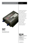
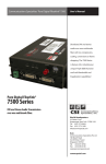
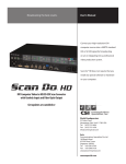
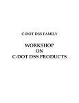
1
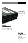
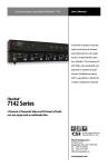
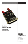
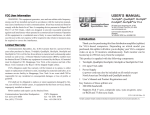
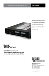
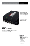
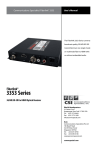
Communications Specialties’ Fiberlink® 6650
User’s Manual
The Fiberlink® 6650 Optical
Power Meter is a high accuracy,
high resolution, microprocessor
controlled optical power meter.
Fiberlink®
6650 Series
Optical Power Meter
World Headquarters
125 Comac Street
Ronkonkoma, New York 11779 USA
Tel: (631) 273-0404
Fax: (631) 273-1638
[email protected]
commspecial.com
Fiberlink® 6650 Series
Contents
Contents
Welcome . . . . . . . . . . . . . . . . . . . . . . . . . . . . . . . . . . . . . . . . . . . . . . . . . . . . . . . . . . . . . . . . . . 3
Features. . . . . . . . . . . . . . . . . . . . . . . . . . . . . . . . . . . . . . . . . . . . . . . . . . . . . . . . . . . . . . . . . . . 3
Package Contents. . . . . . . . . . . . . . . . . . . . . . . . . . . . . . . . . . . . . . . . . . . . . . . . . . . . . . . . . . 3
Technical Specifications. . . . . . . . . . . . . . . . . . . . . . . . . . . . . . . . . . . . . . . . . . . . . . . . . . . . 4
Applications for Fiberlink® 6650 . . . . . . . . . . . . . . . . . . . . . . . . . . . . . . . . . . . . . . . . . . . . 5
Functions. . . . . . . . . . . . . . . . . . . . . . . . . . . . . . . . . . . . . . . . . . . . . . . . . . . . . . . . . . . . . . . . . . 6
Measuring Optical Loss. . . . . . . . . . . . . . . . . . . . . . . . . . . . . . . . . . . . . . . . . . . . . . . . . . . . . 8
Warranty . . . . . . . . . . . . . . . . . . . . . . . . . . . . . . . . . . . . . . . . . . . . . . . . . . . . . . . . . . . . . . . . 10
Operating Pointers. . . . . . . . . . . . . . . . . . . . . . . . . . . . . . . . . . . . . . . . . . . . . . . . . . . . . . . 11
Troubleshooting. . . . . . . . . . . . . . . . . . . . . . . . . . . . . . . . . . . . . . . . . . . . . . . . . . . . . . . . . 11
Maintenance and Repairs . . . . . . . . . . . . . . . . . . . . . . . . . . . . . . . . . . . . . . . . . . . . . . . . 11
Page 2
Fiberlink® 6650 Series User’s Manual
Fiberlink® 6650 Series
Welcome | Features | Package Contents
Welcome
The Fiberlink 6650 Optical Power Meter is a high accuracy, high resolution, microprocessor controlled optical power meter. It has a wide 65 dB dynamic range, and is
calibrated to measure 850, 1300, 1310, and 1550nm, making it ideal for both single mode
and multimode fiber testing, as well as 1490nm for measurement of FTTx PON networks.
Features
• InGaAs photodetector with 2.5mm universal adapter for ST, SC, FC, and other 2.5mm
connectors, 1.25 mm universal adapter for LC connectors
•65 dB dynamic range; calibrated to measure 850, 1300, 1310 and 1550nm
•Works with multimode and single mode fiber
•Graphical LCD display with intuitive user interface
•Simple 2-key operation
•Power measurements shown in dBm, dB, or microwatts
•Display resolution of 0.01 dB
•Long battery life - up to 250 hours on one 9v battery
•On screen battery indicator
•Comes equipped with a rugged and durable rubber boot to protect the instrument
from drops and other hazards
•Optional ruggedized carrying cases available to accommodate 3 or 6 test devices
Package Contents
•One Fiberlink® 6650
•This User’s Manual
• One Non-Rechargeable Lithium Battery (Pre-installed in unit)
• 2.5mm universal adapter (Pre-Installed on unit)
• 1.25 mm universal adapter for LC connectors
Fiberlink® 6650 Series User’s Manual
Page 3
Fiberlink® 6650 Series
Technical Specifications
Technical Specifications
Specifications
Measurement Range:
+5 to -60 dBm
Absolute Accuracy:
+/- 0.15 dB
Resolution:
0.01 dB
Linearity:
+/- 0.20 dB
Wavelengths:
850, 1300, 1310, 1490, 1550nm
Fiber Types:
Single Mode and Multimode
Connector:
InGaAs photodetector with 2.5mm
universal adapter (ST, SC, FC, and
other 2.5mm connectors), and
1.25mm universal adapter
(LC connectors)
Power Requirements:
9 Volt battery or optional
Power Supply for use with
rechargeable battery
Dimensions:
4.94 x 2.175 x 1.28 (inches)
Page 4
Fiberlink® 6650 Series User’s Manual
Fiberlink® 6650 Series
Applications
Applications for Fiberlink® 6650 Optical Power Meter
Below is a list of test and measurement applications that can be performed using the
Fiberlink 6650 optical power meter.
Active Equipment Optical Power Measurements:
Active equipment should be measured periodically for correct power levels.
The transmitters in this equipment have a known power value. The Fiberlink 6650 can be
directly attached to this equipment via a patch cord to check whether the transmitter is
within the manufacturer’s specified power range.
Fiber Continuity Testing:
Continuity can be measured with the Fiberlink 6650 by placing a calibrated light source on
one end of the fiber and the Fiberlink 6650 on the other end. This is also a simple way to
measure the attenuation of the fiber.
Patch Cord Testing:
Optical links that are producing incorrect or poor results may have bad patch cords. The
Fiberlink 6650 can be used to test the attenuation of a patch cord to see if it is usable, or
should be replaced.
Attenuation (Optical Loss) Measurements:
After a fiber cable has been installed and terminated, it must be tested to determine if
the fiber is installed according to standards and specifications. A comparison of the actual
power measurement and the reference value determines if the installation will pass or fail.
Fiberlink® 6650 Series User’s Manual
Page 5
Functions
Fiberlink® 6650 Series
1
2
1
2
3
4
Page 6
5
Fiberlink® 6650 Series User’s Manual
Functions
Fiberlink® 6650 Series
1
Battery Charger Port:
Allows for charging of rechargeable 9 Volt batteries, as well as wall power
operation (Power Supply optional and not included. 9 Volt re-chargeable
battery not included).
2
3
4
5
Do not use battery charging port with non-rechargeable
batteries. There is the potential for explosion and damage
may occur to the unit and/or the user.
1.25/2.5mm Universal Connector Port:
Accepts many popular 1.25mm and 2.5mm ferrule connectors, including ST, SC,
FC and LC.
LCD Screen:
Shows optical power/loss levels, power units, wavelength, and battery status.
Wavelength Selector / Power Button:
Single press changes wavelength; holding the button powers the unit ON or OFF.
Unit Selector / Zero Button:
Single press toggles the measurement units between dBm, dB, and uW.
When in the “dB” mode, holding the button will zero the meter reading. This sets
the current light level at the input detector port 2 as the zero reference level for
subsequent measurements. If you are seting this reference level to zero you must first
make sure that the light source at the input detector port is the desired reference.
As one example, this technique is useful for measuring relative loss or gain in a
link as follows:
➟➟ Set the meter to read in “dB”
➟➟ Set the meter for the wavelength being used by the Transmitter
➟➟ Connect a short fiber cable from the output of an active Transmitter
➟➟ unit to the meter’s input detector port 2
➟➟ Press and hold the Zero button until the meter reading is zero
➟➟ The Transmitter’s output power is now the reference level
➟➟ Disconnect the meter from the Transmitter and connect the fiber cable under test to the Transmitter
➟➟ Connect the meter’s input detector port to the other end of the fiber cable under test
➟➟ The meter will now read, in dB, any loss introduced by the fiber cable under
test
Fiberlink® 6650 Series User’s Manual
Page 7
Measuring Optical Loss
Fiberlink® 6650 Series
Patch Cable
Transmitter
Transmitter Output
Power Measurement:
1)
Connect a short single mode or
multimode fiber to the Fiberlink 6650
and to the transmitter port on the
active equipment under test.
2)
Determine the output wavelength of
the active equipment and then press
the Wavelength button on the Fiberlink
6650 to select the correct wavelength
3) Power on the active equipment
4) Monitor the reading on the screen for
a few seconds. This reading may
fluctuate if the signal is digital. In this
case, estimate the average power level.
Receive Signal Power Measurement:
Transmitter
Measuring the optical power at the receive
link follows the same procedure as above.
However, instead of using a short patch
cable, connect the Fiberlink 6650 at the
point in which the optical receiver will be
placed.
Subtract this new reading from the previous
reading to calculate your loss.
Actual Fiber that will
be used to connect the
transmitter and receiver
Receiver
Page 8
Fiberlink® 6650 Series User’s Manual
Measuring Optical Loss
Fiberlink® 6650 Series
Measuring Optical Loss in a Complete System
The use of the Fiberlink 6650 can be extremely helpful in diagnosing trouble spots in
complex fiber optic systems. The process of calculating loss for each point in the system is
identical to the procedure described on the previous page.
In the example system below, use a short jumper instead of the actual fiber at points 1, 3, 5
and 7 (white circle, black number) to determine the optical loss occurring within the
equipment or patch panel. You will use the actual fiber at points 2, 4, 6 and 8 (black circle,
white number) to determine optical loss occurring within the fiber optic cable.
Subtract the new reading from the previous reading to calculate the loss that has occurred
at that point in the system.
Transmitter
Patch Panel
Optical Matrix
Patch Panel
Receiver
8
1
7
2
6
3
5
4
Fiberlink® 6650 Series User’s Manual
Page 9
Fiberlink® 6650 Series
Warranty
Communications Specialties, Inc. (CSI) warrants that, for a period of three years after
purchase by the Buyer, this product will be free from defects in material and workmanship
under normal use and service. A Return Material Authorization (RMA) number must be
obtained from CSI before any equipment is returned by the Buyer. All materials must be
shipped to CSI at the expense and risk of the Buyer.
CSI’s obligation under this warranty will be limited, at its option, to either the repair or
replacement of defective units, including free materials and labor. In no event shall CSI be
responsible for any incidental or consequential damages or loss of profits or goodwill.
CSI shall not be obligated to replace or repair equipment that has been damaged by fire,
war, acts of God, or similar causes, or equipment that has been serviced by unauthorized
personnel, altered, improperly installed, or abused.
RMA numbers and repairs can be obtained from:
Communications Specialties, Inc.
125 Comac Street
Ronkonkoma, New York 11779 USA
Tel: (631) 273-0404
Fax: (631) 273-1638
RMA numbers can also be obtained from our web site: commspecial.com
Please have your serial number available.
Page 10
Fiberlink® 6650 Series User’s Manual
Fiberlink® 6650 Series
Operating Pointers | Troubleshooting
Maintenance & Repair
Operating Pointers
Remember to check attenuation of the fiber optic cable. The system will only operate
properly if these specifications fall within the range of the system’s loss budget.
Troubleshooting
Multimode fiber optic cable contains an optical fiber with a light carrying “core” that is
only .0025 inches (62.5 microns) in diameter. Single mode fiber optic cable has an even
smaller “core,” only .00032 to .0004 inches (8-10 microns). This is smaller than a human hair!
Therefore, any minute particles of dirt or dust can easily block the fiber from accepting or
radiating light. To prevent this from happening, always use the provided dust caps when
ever optical connectors are exposed to air. It is also a good idea to gently clean the tip of an
optical connector with a lint-free cloth moistened with alcohol whenever dust is suspected.
The status of the LED screen should provide the first clue as to the origin of any operational
failure. If these are off, it usually means that the battery has failed in the unit.
If, after reviewing the above possibilities, the system is still not operating, please contact
the Customer Service Department for further assistance. If you suspect your problem is
caused by the optics or the fiber optic cable, and you have an optical power meter, please
take the appropriate measurements prior to contacting support.
Maintenance and Repairs
The Fiberlink® 6650 Series has been manufactured using the latest semiconductor devices
and techniques that electronic technology has to offer. They have been designed for long,
reliable and trouble-free service and are not normally field repairable.
Should difficulty be encountered, Communications Specialties maintains a complete
service facility to render accurate, timely and reliable service of all products.
The only maintenance that can be provided by the user is to ascertain that optical
connectors are free of dust or dirt that could interfere with light transmission and that
connections are secure and accurate.
All other questions or comments should be directed to our Customer Service Department.
It should be noted that many “problems” can easily be solved by a simple telephone call.
Fiberlink® 6650 Series User’s Manual
Page 11
Communications Specialties’ Fiberlink® 6650
User’s Manual
Fiberlink®
6650 Series
Optical Power Meter
World Headquarters
125 Comac Street
Ronkonkoma, New York 11779 USA
Tel: (631) 273-0404
Fax: (631) 273-1638
[email protected]
commspecial.com
©2014 Communications Specialties, Inc.
All Rights Reserved.
Fiberlink and the starburst logo are
registered trademarks of
Communications Specialties, Inc.
CSI and the triangle designs are trademarks
of Communications Specialties, Inc.
P/N 129696 Rev. C