1
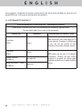
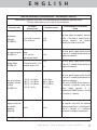
USER MANUAL
E N G L I S H
CONTENT
1
FOREWORD..............................................................................2
2
DENTAL CAMERA INTRODUCTION.....................................................3
3
SAFETY INSTRUCTIONS ................................................................4
4
REGULATORY REQUIREMENTS.........................................................5
5
INSTALLATION .........................................................................10
6
CONNECTING TO A VIDEO SCREEN..................................................11
7
CONNECTING TO A COMPUTER......................................................12
8
DESCRIPTION OF THE CONNECTION BOXES .......................................15
9
MAINTENANCE.........................................................................17
10
AFTER-SALES SERVICE................................................................19
11
TECHNICAL FEATURES................................................................22
2010-03-26 • User’s manual • Sopro 717First
1
E N G L I S H
1
FOREWORD
Congratulations on your purchase of SOPROLIFE
To optimize the use of this device, whilst taking all the necessary precautions, we recommended you read carefully
and follow the owner’s manual.
Please carefully consider the messages “CAUTION”, “WARNING”, and “NOTE” when using the system.
! CAUTION: the term CAUTION describes potential incidents likely to jeopardize safety.
! WARNING: the term WARNING refers to the incidents likely to disturb the smooth running of the imaging system.
NOTE: the term NOTE highlights particular points in order to facilitate the system maintenance or to clarify
important information.
2
Sopro 717First • User’s manual • 2010-03-26
E N G L I S H
2
DENTAL CAMERA INTRODUCTION
It is an extra- and intra-oral camera designed for dental applications. It allows the user to see anatomical and
pathological details that cannot be seen with the naked eye, as well as pathology control and post-treatment.
This camera is composed of a handpiece (SOPRO 717 First), a connection box (DOCK M_USB2, DOCK USB2 or DOCK
MU_USB2), and various accessories necessary for it to work.
SOPRO 717 First
• 1 handpiece integrating the camera electronics and lighting.
• 1 handpiece holder.
• 10 dental barriers.
• Owner’s manual.
• Imaging software (demo version).
DOCK M_USB2
• Connection box with integrated image memory and USB2 digital output.
• Power supply.
• 2.5 metre cable to connect the handpiece to the connection box (5 metres and 7 metres -optional).
• S-Video Y/C cable
• RCA video cable.
• USB cable.
DOCK USB2
• USB2 connection box with a 3.5 meters connecting cable.
DOCK MU_USB2
• Connection box with integrated image memory and USB2 digital output.
• 2.5 metre cable to connect the handpiece to the connection box (5 metres and 7 metres - optional).
• Installation manual.
This device was packaged in a custom carton. This carton should be kept for possible transportation. We provide a
small quantity of complimentary dental barriers necessary for the intra-oral use of the camera. For more details
about purchasing these products, please refer to our catalogue or contact our commercial service.
NOTE:
The device was designed and developed with its accessories in order to guarantee maximum performance and
safety to you. The use of different origin accessories can represent a risk for you, your patients and your device.
2010-03-26 • User’s manual • Sopro 717First
3
E N G L I S H
3
SAFETY INSTRUCTIONS
• Do not expose the dental camera to liquid spray and do not store it in a humid environment (electrocution risk).
• When handling camera always take the appropriate hygiene measures and precautions in order to prevent cross
contamination risks.
• Infection control procedures must be observed when using accessories such as dental barriers in order to
prevent cross contamination risk from one patient to another.
• Install the dental camera in a clean, dry, and well-ventilated place.
• Disconnect the camera from the power supply if you are not going to use it for several days. Do not pull on the
cable.
• Never compress or nip the handpiece cable.
• Never expose the product to high vibrations.
• Do not drop the camera.
• In no way should this camera should be immersed in any liquid, nor should it be autoclaved.
• For each new patient, it is essential to use the dental barriers provided with the camera or provided as a
compliment. Before using the camera, make sure it does not have any sharp edges.
• The surface temperature in the light emission area can be just above 41°C (after several minutes of using it), so
avoid maintaining this emission area in contact with the patient’s mouth.
• The SOPRO 717 First camera is a product using class II LEDs according to IEC 60825. To avoid any ocular risks, do
not stare directly at the LED’s.
NOTE:
If the hygienic protection is torn while examining a patient or if the handpiece was “infected” while withdrawing
the hygienic protector, it is essential to totally disinfect the handpiece. In order to do this: please refer to the
maintenance chapter.
4
Sopro 717First • User’s manual • 2010-03-26
E N G L I S H
4
REGULATORY REQUIREMENTS
4.1. COMPLIANCE WITH STANDARDS AND REGULATIONS
This product was designed and manufactured by a company having an authorized quality system. It meets the
European directive 93/42/EEC requirements relative to medical devices. Therefore, it particularly meets electrical
safety and electromagnetic compatibility standards (IEC) (CEM).
4.2. ELECTROMAGNETIC INTERFERENCE AND ELECTROSTATIC DISCHARGES
Electromagnetic compatibility (CEM) is the ability of electronic device elements to correctly interact in an electronic
environment. Although this dental camera system was designed according to this compatibility and complies with
the electromagnetic interference thresholds established by the regulatory agency, there is no guarantee about
interference likely to occur on a particular installation.
If the device generates interference with radio communication services (which can be determined by switching it
off and on), the user is recommended to try to correct this phenomenon by taking whole or part of the following
measures:
• Change the receiving antenna orientation
• Reposition the product according to the receiver.
• Take the computer away from the receiver.
The SOPRO 717 First camera is designed and tested to be used in a home environment, class B Group 1, according
to CISPR11 standard.
4.3. MEDICAL DEVICE VIGILANCE
As any medical device, this device is subjected to the medical device vigilance dispositions; any serious dysfunction
should then be the subject of a description to the competent authorities and to the manufacturer as soon as possible
and as precisely as possible.
4.4. END OF LIFE
This device bears the recycling symbol
according to the European directive 2002/96/EC about electric and
electronic equipment waste (DEEE or WEEE). By correctly disposing of this device, you will contribute to avoiding
any damage to the environment and human health.
The symbol present on the device or on the accompanying documentation indicates this product cannot be, in any
case, treated as household waste. Therefore, it should be transferred to a waste collection center that handles
electric and electronic equipment recycling.
Respect the standards relative to waste disposal in force in the installation country. For more details about the
2010-03-26 • User’s manual • Sopro 717First
5
E N G L I S H
device treatment, recuperation and recycling, please contact your dental device distributor (or failing that, the
group ACTEON site), so that you can be informed of the procedure.
4.5. ELECTROMAGNETIC COMPTABILITY
Guide and declaration of the manufacturer - electromagnetic emissions
SOPRO device is intended to be used in the electromagnetic environment specified below.
The user should make sure it is used in this environment.
Emission trial
RF emissions
CISPR 11
Compliance
Group 1
RF emissions
CISPR 11
Class B
Harmonic emissions
EN 61000-3-2
Not applicable
Voltage fluctuations / Flicker
EN 61000-3-3
Applicable
6
Electromagnetic environment - Guide
SOPRO device only uses radio energy for its
internal functions. Therefore, its RF emissions
are very low and are unlikely to cause
interference with nearby electronic devices.
SOPRO device may be used in all domestic
environments, including the ones directly
connected to the public low voltage power
distribution network used to supply household
buildings.
Sopro 717First • User’s manual • 2010-03-26
E N G L I S H
Guide and declaration of the manufacturer - electromagnetic immunity
SOPRO device is intended to be used in the electromagnetic environment specified below.
The user should make sure it is used in this environment.
Immunity trial
Electrostatic
discharges
EN 61000-4-2
CEI 60601
Severity level
Compliance level
± 6 kV when in contact
± 8 kV in the air
± 2 kV for the feed
Far transient bursts cables
± 1 kV for the
EN 61000-4-4
input/output cables
Voltage shocks
EN 61000-4-5
Dips, brief outages
and power voltage
variation
EN 61000-4-11
Magnetic field with
the network
frequency
(50/60 Hz)
± 2 kV
± 1 kV
Differential mode ± 1 kV
Common mode ± 2 kV
• <5% UT - for 10 ms
• 40% UT - for 100 ms
• 70% UT - for 500 ms
• <5% UT - for 5 s
3 A/m
± 6 kV
± 8 kV
± 1 kV
N.A.
Electromagnetic environment
Guide
The floor should be wooden, concrete
or tile. If the floor is covered with a
synthetic material, the relative
humidity should be at least 30%.
The main power supply quality should
be one of a traditional commercial or
hospital environment.
The main power supply quality should
be one of a traditional commercial or
hospital environment.
<5% UT 10 ms
<40% UT 100 ms
<70% UT 500 ms
<5% UT 5 s
The main power supply quality should
be one of a traditional commercial or
hospital environment.
If the user of SOPRO device requires it
to continue to operate during main
power supply outages, it is
recommended SOPRO device is fed by
an inverter or a battery.
3 A/m
The magnetic field with the network
frequency should be at a characteristic
level of a location in a traditional
commercial or hospital environment.
Note: UT is the power voltage nominal value applied during the trial.
2010-03-26 • User’s manual • Sopro 717First
7
E N G L I S H
Guide and declaration of the manufacturer - electromagnetic immunity
SOPRO device is intended to be used in the electromagnetic environment specified below.
The user should make sure it is used in this environment.
Immunity trial
CEI 60601
Severity level
Electromagnetic environment
Guide
Compliance
level
Portable and mobile RF communication
devices should not be used at a distance from
SOPRO device including the cables, lower than
the recommended separation distance,
calculated with the applicable formulas
depending on the emitter frequency.
Recommended separation distance
Conducted RF
EN 61000-4-6
Radiated RF
EN 61000-4-3
3 Vrms 150 kHz to 80 MHz 3V
d = 1,16 √P
3 V/m
d = 1,16 √P 80 MHz to 800 MHz
80 MHz to 2.5 GHz
3V/m
d = 2,33 √P 800 MHz to 2.5 GHz
where
is the maximum rated output of the
transmitter in watts (W) by the transmitter
manufacturer and d the recommended
separation distance in metres (m).
The field levels emitted by the fixed RF
transmitters,
determined
by
an
electromagnetic measurement of the sitea,
should be lower than the compliance level in
each frequency band.
Interference may occur in the vicinity of the
devices bearing the following symbol:
Note 1: At 80 MHz and 800 MHz, the higher frequency band applies.
Note 2: These recommendations may not apply in every situation. Electromagnetic wave propagation is
modified by the absorption and reflection due to the structures, objects and persons.
8
Sopro 717First • User’s manual • 2010-03-26
E N G L I S H
a The fixed transmitter field levels, such as the base stations of the radio telephones (cellular/wireless) and the
terrestrial mobile radios, domestic radio, AM, FM, and TV radio communication cannot be theoretically
assessed precisely. To obtain the electromagnetic environment due to the fixed RF transmitters, a site
measurement should be performed. If a field level measured in the use environment of SOPRO device exceeds
the compliance levels above applicable, the good operation of SOPRO device should be checked. If abnormal
operations are proved, some further measures should be taken, such as reorientation or relocation of the
standard device.
b Above the 150 kHz to 80 MHz frequency band, the field level should be lower than 3 V/m.
Recommended separation distances between the portable and mobile RF communication devices
and SOPRO device
SOPRO device is intended to be used in an electromagnetic environment in which the irradiated RF disturbances
are checked. The user of SOPRO device can help to avoid electromagnetic interference by maintaining a minimal
distance between the portable and mobile RF communication devices (transmitters) and the recommended SOPRO
device such as recommended below, depending on the maximum output power of the communication device.
Separation distance depending on the transmitter frequency m
Rated maximal output
power of the
transmitterW
150 kHz to 80 MHz
80 MHz to 800 MHz
800 MHz to 2,5 GHz
d = 1.6 √P
d = 1.6 √P
d = 2.33 √P
0.01
0.116
0.116
0.233
0.1
0.366
0.366
0.736
1
1.16
1.16
2.33
10
3.66
3.66
7.36
100
11.6
11.6
23.3
For the transmitters whose maximal output is not listed above, the recommended separation distance d in metres
(m) can be determined by using the equation applicable to the transmitter frequency, where P is the maximal
output of the transmitter in watts (W) rated by the transmitter manufacturer.
Note 1: At 80 MHz and at 800 MHz, the separation distance given in the higher frequency band applies.
Note 2: These recommendations may not apply in every situation. The electromagnetic wave propagation is
modified by absorption and reflection due to the structures, objects and persons.
2010-03-26 • User’s manual • Sopro 717First
9
E N G L I S H
5
INSTALLATION
5.1. CONNECTING
Fastening the handpiece holder:
1. Choose a smooth area that can be easily accessible for use.
2. Use the wipe provided to clean the surface on which you are going to fasten the holder.
3. Remove the double-sided adhesive tape protection that is on the support, place it, and then press it into place
several times.
The maximum adhesive performance is obtained after two hours. So, avoid any stress on the holder during this two
hour period.
! WARNING:
This holder is equipped with magnets that can damage devices sensitive to magnetic fields. Make sure you do not
install this holder near these devices (cathode ray tube video screen, magnetic videotapes, etc.).
5.2. FURTHER CONNECTION BOXES (OPTIONAL)
You can install a connection box near each dental chair (no limitation). You will just have to transport the handpiece
from one chair to the other.
The handpiece holder is intended to maintain the connecting cable connector when the cable is not linked to the
handpiece.
When you disconnect the handpiece connecting cable to take it to another chair (or when you put the handpiece
on its holder), the last stored image displays on the screen* (or the last four if you were in four-image mode, or the
color-bar pattern if no image was stored).
(* Except for the DOCK USB2)
5.3. FOCUSING ADJUSTMENT
On the handpiece, there is a rotating ring used to focus from “0” to infinite. To simplify handling, we have preset
three positions corresponding to the main dental camera uses.
Extra-oral (Portrait).
Intra-Oral (1 to 5 teeth).
Macro (details that cannot be seen with naked eye).
10
Sopro 717First • User’s manual • 2010-03-26
E N G L I S H
6
CONNECTING TO A VIDEO SCREEN
6.1. CONNECTION OF DOCK M_USB2
• Connect the video cable (preferably Y/C “S-video”) between the connection box and the monitor video input.
• Connect the connecting cable between the connection box and the handpiece.
• If you prefer using a footswitch rather than SoproTouch to freeze the image, you just have to connect the
footswitch (optional) to the connection box. With this configuration, SoproTouch is inhibited.
• Connect the power supply to the outlet, and then to the connection box (the green indicator light should be on).
• Only use the power supply provided with the connection box.
6.2. CONNECTION OF DOCK MU_USB2
• Please refer to DOCK MU_USB2 integration manual for its connections.
• Connect the connecting cable to the handpiece.
• Connect the video cable (preferably Y/C “S-video”) between the connection box and the monitor video input.
6.3. OPERATION OF SOPROTOUCH IMAGE FREEZE ON SOPRO 717 FIRST
• When powering on, the camera automatically selects the single-image mode.
• To switch to four-image mode, press SoproTouch
for more than three seconds (until a black flash appears
on the screen or, if you have chosen to use a footswitch, press it for more than three seconds).
• Perform the same procedure to switch back to single-image mode.
• In single-image mode, you just have to slightly touch SoproTouch
(or briefly press the footswitch once) as
soon as the desired image appears on the monitor. The image is automatically stored in the camera and displayed
on the screen. If you want to return to direct mode, you just have to slightly touch SoproTouch
press the footswitch).
once more (or
• Another little gentle touch on SoproTouch
(or press on the footswitch) will freeze another image by deleting
the previous one.
• In four-image mode, the image is stored in one of the quarters of the screen when you slightly touch SoproTouch
(or press the footswitch) and remains displayed on the screen. Another little slight touch on SoproTouch
(or press of the footswitch) will return the image to direct mode. A third little slight touch (or pressof the footswitch)
will store a second image in another quarter of the screen and so on until four images are obtained.
2010-03-26 • User’s manual • Sopro 717First
11
E N G L I S H
7
CONNECTING TO A COMPUTER
7.1. REQUIRED CONFIGURATION FOR THE COMPUTER
To use the Sopro 717 First system, you must make sure the computer and its peripherals do not have any use
limitation that could concern life safety. It should also meet the following requirements:
Minimal configuration
Recommended configuration
Operating system
Windows 2000 Pro SP4 - XP Pro SP1
Windows XP Pro SP3 – VISTA Business SP1
Processor
Intel® Pentium III – 500 MHz
Intel® Core 2
Memory
512 MB
2 GB
Hard disk
20 GB
160 GB
USB ports
2 x USB2.0 Hi-Speed ports
4 x UB 2.0 Hi-Speed ports
Video board
Graphic board 32 MB of unshared
video RAM compatible with DirectX 9
Graphic board with Nvidia chipset or exclusive video ATI /
256 MB of unshared video RAM compatible with DirectX 9
or higher.
USB Chipset
Intel ou NEC
Intel ou NEC
Screen resolution
1024 x 768
1024 x 768 or higher
Standard
IEC 60950
IEC 60601-1
7.2. DOCK M_USB2 CONNECTION
• Connect the USB cable between the connection box and one of the computer USB ports.
• Connect the connecting cable between the connection box and the handpiece.
• If you prefer using a footswitch rather than SoproTouch
to freeze the image, you just have to connect the
footswitch (optional) to the connection box. With this configuration, SoproTouch is inhibited.
• Connect the power supply to the outlet, and then, to the connection box (the green indicator light should be on).
7.3. DOCK MU_USB2 CONNECTION
• Refer to DOCK MU_USB 2 integration manual.
• Connect the connecting cable to the handpiece.
• Connect the USB cable between the connection box and one of the computer USB ports.
12
Sopro 717First • User’s manual • 2010-03-26
E N G L I S H
7.4. DOCK USB2 CONNECTION
• Connect the USB cable to one of the computer USB ports.
• Connect the connecting cable to the handpiece.
7.5. SOPRO IMAGING SOFTWARE INSTALLATION
•Insert the SOPRO Imaging CD-ROM into the driver. It will be executed automatically.
! WARNING:
If the CD-ROM does not execute automatically or if the operating system is prior to Windows XP SP1, follow the
following instructions:
- Go to the Start menu > Execute.
- Type D:\setup.exe (replace D by the letter of the CD-ROM driver).
- And then, click on OK. The file instantly executes. Then follow the steps from the below point.
• A dialog box opens - it is the main menu window allowing the installation of a certain number of programs related
to SOPRO Imaging application.
NOTE:
Clicking on the key “Browse this CD-ROM” accesses a Windows browse window from which it is possible to consult
the whole content of the CD-ROM. At the CD-ROM root, there are the files allowing an automatic launch and/or
a manual setup.
- Located in the directory “Document” and its subdirectories are all the documents about the Sopro Imaging
software, digital x-ray systems, intra oral cameras and SOPROLIFE system. These documents are in PDF format.
Be sure to correctly install Acrobat Reader in case of reading difficulties.
- The Drivers directories contain the drivers necessary for the use of hardware accepted by SOPRO Imaging
(Sopix system, SOPRO cameras in USB 1 and USB 2, Hasp protection key).
-The directory SOPRO Imaging contains the SOPRO Imaging installation program.
- The directory “Tools” contains
• Click on “Install SOPRO Imaging”. A window displays; select the desired language during the installation process.
• A dialog box opens - it displays the software license to be entirely read to continue the installation. Once the terms
are read, click on “Next”.
• By default, the SOPRO Imaging software will automatically install in the directory “C:\Program Files\SOPRO
Imaging”. To start installing the software, click on “Next”.
• Once the installation is completed, a dialog box displays. Click on “Finish”.
2010-03-26 • User’s manual • Sopro 717First
13
E N G L I S H
! WARNING:
To obtain the best performance possible when using the SOPRO Imaging software, it is recommended to install
DirectX 9.0c. In order to do this, click on the key “Install DirectX 9.0c” and then, follow the displayed instructions.
DirectX 9.0c is a Microsoft® product. In case of difficulties when installing this product, consult the information
provided by this editor. In order to ensure maximal compatibility with all the installed systems (computers,
Windows, and word processing version) it was decided to provide the documents available on the CD-ROM in PDF
format. This format developed by ADOBE® Company can be read with the
Acrobat Reader service program.
If Acrobat Reader is not installed on the computer or the version is not recent enough, click on the key “Install
Acrobat Reader” and then follow the instructions. Acrobat Reader is an ADOBE® product. In case of difficulties
when installing this product, consult the information provided by this editor.
7.6. SOPRO IMAGING SOFTWARE CONFIGURATION WITH SOPRO 717 FIRST CAMERA
Refer to the SOPRO Imaging owner’s manual that is on the SOPRO Imaging CD-ROM in the document directory.
14
Sopro 717First • User’s manual • 2010-03-26
E N G L I S H
8
DESCRIPTION OF THE CONNECTION BOXES
8.1. DOCK M_USB2 POWER SUPPLY
The dental camera power supply is connected to the power outlet. The other end of the cord is connected to the
dock where the symbol 6 V
is located (PHIHONG, PSA 10R-060 Model or FRIWO, MPP15 FW 7555M/06 model).
The power supply automatically adapts to the electric networks 115 V~ - 230 V~; 60 Hz - 50 Hz; 0.5 A. The camera
voltage is powered by 6V
of a continuous low voltage type.
8.2. DOCK MU_USB2 POWER SUPPLY
The electrical connection of this connection box should be performed by the installer. The dental camera power
supply is performed through the connection box that should be connected 24 V~; 50 Hz - 60 Hz; 10 VA.
8.3. DOCK USB2 POWER SUPPLY
The dental camera electrical supply is directly performed through the computer USB port. The voltage powering
the camera is of continuous 5 V
low voltage type (0.5 A).
8.4. VIDEO AND USB OUTPUTS
This camera has two independent video outputs* - a composite one and a Y/C “S-Video” one.
One of these two outputs should be connected to the monitor video input (preferably Y/C “S-Video”). According to
the connection box used, this camera has a digital USB 2.0 output that can be connected to a computer USB2 port.
(* Except for the DOCK USB2)
8.5. FOOTSWITCH
The footswitch should be connected here *
(* Except for the DOCK USB2)
, if you have selected it to freeze the image.
2010-03-26 • User’s manual • Sopro 717First
15
E N G L I S H
8.6. IDENTIFICATION
The indications born on the boxes identify the dental camera according to the international standards CEI 601- 1
and CEI 417.
Video output.
Handpiece connection.
Footswitch connection.
Continuous voltage.
USB2 output.
“BF type camera”.
!
Caution, please consult the ACCOMPANYING DOCUMENTS.
Disposal of electric and electronic equipment marketed after 13/August/2005. This symbol indicates
that the product cannot be treated as domestic waste.
For medical devices, this symbol is associated to the manufacturing year (expressed with four digits).
For medical devices, this symbol is associated to the manufacturer name and address.
Product compliance according to the European directive 93/42/EEC relative to medical devices.
Grounding.
The devices that connect to video or USB outputs should comply with IEC 60950 standard.
16
Sopro 717First • User’s manual • 2010-03-26
E N G L I S H
9
MAINTENANCE
The intra-oral camera does not need any maintenance if it is used according to the manufacturer’s use and cleaning
instructions.
Before first using it, it is imperative to follow the complete disinfecting procedure.
Any intra-oral camera returning from servicing or maintenance should be completely disinfected before being used.
! WARNING :
Do not use products containing:
• Ammoniac, trichloroethylene
• Dichloroethylene
• Ammonium hydrochlorid
• Chlorinated and aromatic hydrocarbon
• Ethylene dichloride
• Methylene chloride
• Ketones
Using products containing these chemicals risk deterioration of plastic parts.
! WARNING :
Do not directly spray disinfecting products on SOPRO products.
! WARNING:
Infection control procedures must be observed when handling the camera or using accessories such as dental
barriers; in order to prevent cross contamination risk from one patient to another.
2010-03-26 • User’s manual • Sopro 717First
17
E N G L I S H
9.1 HANDPIECE OR CONNECTION BOX MAINTENANCE
DESCRIPTION
Disinfecting.
RECOMMENDATIONS
Surface cleaning and
disinfecting wipes e.g.
Septol™ Wipes from
Pierre Rolland.
USE INSTRUCTIONS AND PRECAUTIONS
✓
✘
Take the wipe, remove excess Do not scrub
moisture, and then wipe the Do not rinse.
equipment until visible
Do not immerse in a
cleanliness is obtained.
disinfecting liquid.
Allow to dry in the open air.
Carefully close the packaging
box.
NOTE :
In case of contact with blood or important soiling, it is strongly recommended to follow a disinfecting process. First
of all, clean the handpiece with disinfecting wipes, then roll up several disinfecting wipes around the handpiece
and leave on for 15 minutes.
18
Sopro 717First • User’s manual • 2010-03-26
E N G L I S H
10
AFTER-SALES SERVICE
10.1. WARRANTIES
SOPRO ensures its products to be free from material and manufacturing defects for a period of one (1) year coming
into force at the purchase date. This warranty does not apply to misused, modified, untended, or accidentally
damaged products, or products subject to abnormal use and handling conditions. The distributors, other than
ACTEON Group’s subsidiaries, are not authorized to apply a warranty more extended on behalf of SOPRO.
The entire liability of SOPRO is limited to its convenience when replacing or repairing, free of charge, the defective
product if it has been sent to SOPRO After-Sales Service. This applies for the warranty period.
Outside of France, access to the warranty is only possible if the product was bought in one of the points of sale
authorized by SOPRO in the country where it will be used.
THIS WARRANTY CONSTITUTES THE ONLY AND UNIQUE REMEDY. IT REPLACES ANY OTHER WARRANTY, FOR
EXAMPLE, A WARRANTY OF ADEQUACY TO A PARTICULAR AIM, SHOULD IT BE EXPLICIT OR IMPLICIT. SOPRO SHALL
NOT BE LIABLE FOR ANY PARTICULAR DAMAGE, INDIRECT, ACCIDENTAL OR CONSEQUENTIAL NOR FOR ANY
DETERIORATION OR DATA LOSS, ON A CONTRACTUAL, NON-CONTRACTUAL OR OTHER BASIS.
The liability exclusion or limitation for direct or indirect damages does not apply under the regulatory or legal rules
in force in some countries and the present exclusion may not apply to a purchaser in those countries.
2010-03-26 • User’s manual • Sopro 717First
19
E N G L I S H
10.2. IN CASE OF FAILURE
PROBLEMS
With a video monitor
No image displays on the
screen and camera LEDs are
not on.
Camera switches on but no
image displays on the screen.
CAUSES
• Defective power
1. Check the power supply is correctly connected to
supply.
the network and to the connection box.
•connection problem. 2. Check the connecting cable is correctly connected
to the handpiece and to the connection box.
• Defective monitor 1. Check the video cable is correctly connected to the
power supply.
monitor and to the connection box.
• Connection problem. 2. Check the monitor is switched on.
Monitor configuration. Check the video monitor configuration is correctly set
up (brightness, contrast, saturation, etc.)
An image displays on the
screen, but the quality is not
satisfactory.
An image displays, but it is not • Rotating ring.
really clear (blurry)
• Hygienic protector.
With a computer
No image displays on the
screen and the camera LEDs
are not on.
Camera switches on but no
image displays on the screen.
An image displays on the
screen, but the quality is not
satisfactory.
1.Check the rotating ring is correctly positioned
(Extra oral
, Intra oral
, macro ).
2. Check the hygienic protector is correctly positioned
on the camera head.
• Defective power
1. Vérifier que l’alimentation secteur est bien
supply.
connectée au réseau et au boîtier de connexion.
•connection problem. 2. Vérifier que le câble de liaison est bien connecté à
la pièce à main et au boîtier de connexion.
•Configuration
1. Check the camera is correctly set up in Sopro
Imaging (please, refer to Sopro Imaging user's
manual).
2. Check the camera is correctly detected in the
•Driver
device driver (correct installation of its driver).
• Connection problem. 3. Check the USB cable coming from the DOCK is
correctly connected to the HUB.
Camera driver
configuration
An image displays, but it is not • Rotating ring.
really clear (blurry)
• Hygienic protector.
20
SOLUTIONS
Check the camera configuration in the Sopro Imaging
software (brightness, contrast, saturation, etc.).
Please refer to Sopro Imaging user’s manual.
1. Check the rotating ring is correctly positioned
(Extra oral
, Intra oral
, macro
).
2. Check the hygienic protector is correctly positioned
on the camera head.
Sopro 717First • User’s manual • 2010-03-26
E N G L I S H
The dental camera should be sent to us in its totality (connection box, handpiece, cables). Please enclose your
packing list with a brief explanatory note relative to the noticed defect.
If some parts constituting the camera happen to break, it is imperative to send in everything so that the defective
parts can be replaced.
When your material is returned to you, you should check its condition and note any reservations on the delivery slip,
if necessary. You will then have 48 hours to confirm by registered letter sent to the carrier. After 48 hours, the carrier
will be able to deny these reservations.
If any material we sent was damaged during transportation, the repair charges will be billed either to the carrier
(if the reservations were made within the period) or to the recipient. Check as soon as possible that all material is
correctly working.
2010-03-26 • User’s manual • Sopro 717First
21
E N G L I S H
11
TECHNICAL FEATURES
SOPRO 717 FIRST
• High sensitivity CCD 1/4”.
• Resolution: (752 x 582) PAL; (768 x 494) NTSC.
• Definition: 470 lines.
• Sensitivity: 2 lux.
• Lighting: eight LEDs.
• Adjustment: three preset positions (Extra-oral, Intra-oral, Macro).
• Non-inverted image.
• Image freezing through SoproTouch or footswitch (option).
• Viewing angle: 70°.
• Cable length: 2.5m.
• Handpiece dimensions: L: 200; W: 28; H: 24 mm.
• Usable part dimensions: W: 13 x H: 8 mm.
• Handpiece weight: 75 g.
DOCK M_USB2
• Memory one and four images.
• Power supply: 115 V˜ - 230 V˜; 60 Hz - 50 Hz
• 1 PAL or NTSC video output.
• 1 PAL or NTSC S-video output.
• 1 digital USB output 2.0.
• Controller dimensions: L: 145; W: 130; H: 35 mm.
• Controller weight: 245 g.
DOCK MU_USB2
• Memory one and four images.
• Power supply: 24 V~; 50 Hz - 60 Hz.
• Consumption: 10 VA.
• 1 PAL or NTSC video output.
• 1 PAL or NTSC S-video output.
• 1 digital USB output 2.0.
• Controller dimensions: L: 100; W: 72; H: 36 mm.
• Dock weight: 190 g.
22
Sopro 717First • User’s manual • 2010-03-26
E N G L I S H
DOCK USB2
• Cable length: 3.5 m.
• 1 digital USB output 2.0.
• Controller dimensions: L: 100; l: 46; H: 20 mm.
• Dock weight: 165 g.
• BF-type applied part.
• Operating temperature: +10°C to +40°C.
• Storage temperature: -20°C to +45°C.
• Relative humidity: 10 % to 90 %.
• Atmospheric pressure: 900 hPa to 1,060 hPa.
• Continuous service.
• Not protected against water chutes (IPX0).
• Not adapted to the use in presence of an anaesthetic mixture flammable with air, oxygen or dinitrogen
monoxide.
• Complies with the European directive 93/42/EEC.
• Complies with EC60601-1 standard.
• Complies with IEC60601-2-18 standard.
• Complies with UL 60601-1 et CSA 60601-1 standard.
2010-03-26 • User’s manual • Sopro 717First
23
Non contractual document - Ref. 011353 A - Copyright © 2010 SOPRO. All rights reserved. No information or part of this document may be reproduced or transmitted in any form without the prior permission of SOPRO.
Z A C A t h é l i a I V • Av e n u e d e s G e n é v r i e r s • 1 3 7 0 5 L A C I O TAT c e d e x • F R A N C E
Tél +33 (0) 442 98 01 01 • Fax +33 (0) 442 71 76 90 • E-mail: [email protected] • www.sopro.acteongroup.com