1
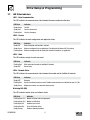
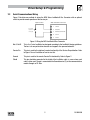
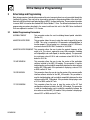
MCH Series Drives
LonWorks Communications Guide
About These Instructions
This documentation applies to the use of an MCH Series Variable Frequency Drive with LonWorks protocol and
should be used in conjunction with the MCH Series Installation and Operation Manual (Document MH01) that
shipped with the drive. These documents should be read in their entirety as they contain important technical data
and describe the installation and operation of the drive.
LON®, LonTalk® and LonWorks® are registered trademarks of the Echelon Corporation, San Jose CA 95126,
http://www.echelon.com; [email protected].
Anybus® and ABS-S® are registered trademarks of HMS Industrial Networks AB, Sweden, USA, Germany and
other countries, http://www.anybus.com.
Modbus ™ is a registered trademark of Schneider Electric, founder of Modbus-IDA, http://www.modbus-IDA.org.
© 2003 AC Technology Corporation
No part of this documentation may be copied or made available to third parties without the explicit written approval
of AC Technology Corporation. All information given in this documentation has been carefully selected and tested
for compliance with the hardware and software described. Nevertheless, discrepancies cannot be ruled out. AC
Tech does not accept any responsibility nor liability for damages that may occur. Any necessary corrections will be
implemented in subsequent editions.
Contents
1 Safety Information..............................................................................................................1
1.1
Warnings, Cautions and Notes...............................................................................1
1.1.1 General.....................................................................................................1
1.1.2 Application................................................................................................1
1.1.3 Installation................................................................................................1
1.1.4 Electrical Connection.................................................................................2
1.1.5 Operation..................................................................................................2
2 Introduction........................................................................................................................3
2.1
Hardware Description............................................................................................3
2.2
LED Status Indicators.............................................................................................4
2.3
Serial Communications Wiring...............................................................................5
3 Drive Setup and Programming............................................................................................6
3.1
Added Programming Parameters...........................................................................6
3.2
Bus Configuration Parameters................................................................................7
3.3
Omitted Parameters and Selections.......................................................................9
3.4
Modified Parameters and Selections......................................................................9
3.5
Serial Communication Setup..................................................................................10
4 MCH LonWorks® Network Variables..................................................................................12
4.1
LonWorks® Network Variable Map........................................................................12
4.2
Supported Input Network Variables........................................................................13
4.3
Supported Output Network Variables......................................................................15
4.4
Supported Configuration Network Variables...........................................................19
4.5
LonWorks XIF Files................................................................................................23
i
RG-MHLON
Safety Information
1
Safety Information
1.1
Warnings, Cautions and Notes
1.1.1 General
Some parts of Lenze controllers (frequency inverters, servo inverters, DC controllers) can be live, moving
and rotating. Some surfaces can be hot.
Non-authorized removal of the required cover, inappropriate use, and incorrect installation or operation
creates the risk of severe injury to personnel or damage to equipment.
All operations concerning transport, installation, and commissioning as well as maintenance must be
carried out by qualified, skilled personnel (IEC 364 and CENELEC HD 384 or DIN VDE 0100 and IEC report
664 or DIN VDE0110 and national regulations for the prevention of accidents must be observed).
According to this basic safety information, qualified skilled personnel are persons who are familiar with
the installation, assembly, commissioning, and operation of the product and who have the qualifications
necessary for their occupation.
1.1.2 Application
Drive controllers are components designed for installation in electrical systems or machinery. They are
not to be used as appliances. They are intended exclusively for professional and commercial purposes
according to EN 61000-3-2. The documentation includes information on compliance with EN 61000-3-2.
When installing the drive controllers in machines, commissioning (i.e. the starting of operation as directed)
is prohibited until it is proven that the machine complies with the regulations of the EC Directive 98/37/EC
(Machinery Directive); EN 60204 must be observed.
Commissioning (i.e. starting drive as directed) is only allowed when there is compliance to the EMC Directive
(89/336/EEC).
The drive controllers meet the requirements of the Low Voltage Directive 73/23/EEC. The harmonised
standards of the series EN 50178/DIN VDE 0160 apply to the controllers.
The availability of controllers is restricted according to EN 61800-3. These products can cause
radio interference in residential areas. In the case of radio interference, special measures may be
necessary for drive controllers.
1.1.3 Installation
Ensure proper handling and avoid excessive mechanical stress. Do not bend any components and do not
change any insulation distances during transport or handling. Do not touch any electronic components
and contacts. Controllers contain electrostatically sensitive components, which can easily be damaged by
inappropriate handling. Do not damage or destroy any electrical components since this might endanger
your health! When installing the drive ensure optimal airflow by observing all clearance distances in the
drive's user manual. Do not expose the drive to excessive: vibration, temperature, humidity, sunlight, dust,
pollutants, corrosive chemicals or other hazardous environments.
1
RG-MHLON
Safety Information
1.1.4 Electrical Connection
When working on live drive controllers, applicable national regulations for the prevention of accidents (e.g.
VBG 4) must be observed.
The electrical installation must be carried out in accordance with the appropriate regulations (e.g.
cable cross-sections, fuses, PE connection). Additional information can be obtained from the regulatory
documentation.
The regulatory documentation contains information about installation in compliance with EMC (shielding,
grounding, filters and cables). These notes must also be observed for CE-marked controllers.
The manufacturer of the system or machine is responsible for compliance with the required limit values
demanded by EMC legislation.
1.1.5 Operation
Systems including controllers must be equipped with additional monitoring and protection devices according
to the corresponding standards (e.g. technical equipment, regulations for prevention of accidents, etc.).
You are allowed to adapt the controller to your application as described in the documentation.
DANGER!
• After the controller has been disconnected from the supply voltage, do not touch the live
components and power connection until the capacitors have discharged. Please observe the
corresponding notes on the controller.
• Do not continuously cycle input power to the controller more than once every three minutes.
• Close all protective covers and doors during operation.
WARNING!
Network control permits automatic starting and stopping of the inverter drive. The system design
must incorporate adequate protection to prevent personnel from accessing moving equipment
while power is applied to the drive system.
Table 1: Pictographs used in these instructions
Pictograph
RG-MHLON
Signal word
Meaning
Consequences if ignored
DANGER!
Warning of Hazardous Electrical
Voltage.
Reference to an imminent danger that may
result in death or serious personal injury if the
corresponding measures are not taken.
WARNING!
Impending or possible danger
for persons
Death or injury
STOP!
Possible damage to equipment
Damage to drive system or its surroundings
NOTE
Useful tip: If observed, it will
make using the drive easier
2
Introduction
2
Introduction
This document explains how to connect an MCH Drive to a LonWorks® network. It is intended as a serial
communications supplement only and will not discuss normal drive operations. For more information
regarding normal drive setup and functionality, refer to the MCH Installation and Operation Manual (MH01).
LonWorks® technology is a complete platform for implementing control network systems. These networks
consist of intelligent control devices or nodes that interact with their environment and communicate with
each other using a common, message based protocol (LonTalk®). A LonWorks® network can consist of
up to 32,385 nodes divided into 255 subnets (127 nodes/subnet).
2.1
Hardware Description
To connect to a LonWorks® network, the MCH Drive utilizes an Anybus-S® Drive Profile Embedded
Interface Card that supports Version 1.1 of the LonMark® 6010 Functional Profile for Variable Speed Motor
Drives. This Anybus-S LonWorks (ABS-LON®) module is located inside of the bypass or option box that is
attached to the MCH Drive.
The ABS-LON® module communicates according to the LonTalk® protocol. This means that it can
communicate with all LonWorks® nodes that comply with this protocol, but it does not necessarily mean
that all services available in the LonTalk® protocol are supported.
The ABS-LON® module uses the FTT-10A (Free Topology Twisted Pair) transceiver from Echelon Corporation.
This is the most commonly used twisted-pair media in building automation and this architecture supports
star, bus and loop wiring. The FTT-10A transceiver connects to a twisted pair cable with a baud rate of 78
kbit/s. The FTT-10A transceiver appears as a high impedance to the network when unpowered, and does
not interfere with network communications when powered down.
Figure 1 identifies the components of the communications module intended for user interaction.
Watchdog LED
Socket for LonWorks
Bus Connector
Service Pin Pushbutton
1
2
4
3
LED Status Indicators
Figure 1: MCH LonWorks® Comm Module
3
RG-MHLON
Drive Setup & Programming
2.2
LED Status Indicators
LED 1 - Drive Communication
This LED indicates the communication status between the comm module and the drive.
LED State
Indicates:
Steady Green
Link OK
Steady Red
Link lost, permanent
Flashing Red
Link lost, temporary
LED 2 - Service
This LED indicates the node configuration and application status.
LED State
Indicates:
Steady OFF
Node configured and installed in network
Steady Green
Node not configured, has no application; Error detected by Neuron Self Test routine
Flashing Green
Node not configured and not installed in network but node has an application
LED 3 - Wink
This LED indicates receipt of a wink command.
LED State
Indicates:
Flashing Red
Wink command received on LonWorks® network
Steady OFF
Normal state
LED 4 - Network Status
This LED indicates the communication status between the module and the LonWorks® network.
LED State
Indicates:
Steady OFF
No power
Flashing Red
Receive heartbeat timeout occurred; Fieldbus communication loss indicated to host: RX_FAIL
Steady Green
Module and network are communicating correctly
Watchdog LED (WD)
This LED indicates module, drive and software status.
LED State
Indicates:
Flashing Green 1Hz
Module initialized and running properly
Flashing Green 2Hz
Module not initialized
Flashing Red 1Hz
Hardware check fault
Flashing Red 4Hz
Drive initialization failed
Steady Orange
Software download enabled
RG-MHLON
4
Drive Setup & Programming
2.3
Serial Communications Wiring
Figure 2 illustrates one method of wiring the MCH Series LonWorks® Bus Connector with an optional
switch to provide remote operation of the service pin.
Optional Switch
MCH LonWorks Bus Connector
(For remote
operation of
service pin)
1
Shield
2
Ground
3
Remote Service Pin
4
Net A
5
Net B
Figure 2: Wiring the MCH LonWorks® Bus Connector
Net A, Net B
This is the 2-wire LonWorks bus designed according to the LonMark® design guidelines.
The bus is of non-polarization character and supports line-powered networks.
Service Pin
This pin is used for the (optional) remote functionality of the Service Pin pushbutton. Refer
to Figure 2 for an illustration on how to wire this.
Ground
This pin is used for the remote Service Pin functionality. Refer to Figure 2.
Shield
This pin should be connected to the shield of the LonWorks cable, in cases where such
cable is to be used. The pin is connected to the Ground terminal (2) on the communications
module through an RC-filter.
5
RG-MHLON
Drive Setup & Programming
3
Drive Setup and Programming
Most drive parameters (including those required for serial communications) are not accessible through the
LonWorks® interface. They can only be accessed by entering the Programming Mode of the drive itself.
Refer to the MCH Installation and Operation Manual (MH01) for more information. The parameter information
in manual MH01 is based on the standard MCH Series Modbus™ Drive. The differences between the drive
programming parameters described in the manual and those that exist in the MCH Series LonWorks®
Drive are explained in sections 3.1-3.4 herein.
3.1
Added Programming Parameters
60 SERIAL TIMEOUT
This parameter makes the serial watchdog timeout period selectable.
(Section 3.5)
86 MOTOR RATED SPEED
This parameter allows the user to enter the nominal speed of the motor
in RPM. This value is required for LON parameter nvoSpeedActRpm to
function properly. This parameter has a minimum value of 1 RPM and a
maximum value of 65000 RPM. The default is 1800 RPM.
89 MOTOR RATED FREQUENCY This parameter allows the user to enter the nominal frequency of the
motor in Hz. This value is required for many LON parameters (including
nviDrvSpeedStpt and nvoDrvSpeed) to function properly. This parameter
has a minimum value of 0.00 Hz and a maximum value of 650.00 Hz. The
default is 60.00 Hz.
125 APP REVISION
This parameter allows the user to view the version of the application
software installed in the ABS_LON module. This parameter is used for
troubleshooting and to establish compatibility between the drive software
and the ABS_LON module. If this parameter is displaying a value of 0104
or 9999, contact AC Tech.
126 CPI REVISION
This parameter allows the user to view the version of the common profile
interface software installed in the ABS_LON module. This parameter is
used for troubleshooting and to establish compatibility between the drive
software and the ABS_LON module. If this parameter is displaying a value
of 0124 or 9999, contact AC Tech.
127 CFG REVISION
This parameter allows the user to view the version of the AC Tech
configuration software installed in the ABS_LON module. This parameter
is used for troubleshooting and to establish compatibility between the
drive software and the ABS_LON module. If this parameter is displaying a
value of 0001 or 9999, contact AC Tech.
RG-MHLON
6
Drive Setup & Programming
3.2
Bus Configuration Parameters
The Bus configuration parameters are only used to provide additional information about the installation
state of the drive. As the address information usually is assigned from the network side in a LonWorks
network, in the programming mode of the drive, these parameters are read-only.
100 NODE STATE
This parameter contains the current state of the network interface. Configured
Online is the normal run-time mode and means that the drive is commissioned
and online. Soft/Bypass/Hard Offline means the node is not participating actively
on the network.
Value
0
1
2
3
4
5
6
7
Node State
Unknown State
Unconfigured
Applicationless
Configured Online
Configured Offline
Soft Offline
Configured Bypass Offline
Hard Offline, Bypass Offline
101 NEURON ID [5]
Byte 6 of the unique Neuron ID (MSB)
102 NEURON ID [4]
Byte 5 of the unique Neuron ID
103 NEURON ID [3]
Byte 4 of the unique Neuron ID
104 NEURON ID [2]
Byte 3 of the unique Neuron ID
105 NEURON ID [1]
Byte 2 of the unique Neuron ID
106 NEURON ID [0]
Byte 1 of the unique Neuron ID (LSB)
107 NODE ADDRESS 1
Indicates the ID of the node within this subnet. A value of 0 means that it is not
assigned.
108 NODE SUBNET 1
Indicates to which subnet this node belongs. A value of 0 means that it is not
assigned.
7
RG-MHLON
Drive Setup & Programming
Each domain in a LonWorks network has a unique ID of 0, 1, 3 or 6 bytes in length. If the ID is shorter than
6 bytes, it is left justified in the following parameters (109-114).
109 DOMAIN ID 1 [5]
Byte 6 of the domain ID (MSB)
110 DOMAIN ID 1 [4]
Byte 5 of the domain ID
111 DOMAIN ID 1 [3
Byte 4 of the domain ID
112 DOMAIN ID 1 [2]
Byte 3 of the domain ID
113 DOMAIN ID 1 [1]
Byte 2 of the domain ID
114 DOMAIN ID 1 [0]
Byte 1 of the domain ID (LSB)
115 NODE ADDRESS 2
Indicates the ID of the node within this subnet. A value of 0 means that it is not
assigned.
116 NODE SUBNET 2
Indicates to which subnet this node belongs. A value of 0 means that it is not
assigned.
Each domain in a LonWorks network has a unique ID of 0,1,3 or 6 bytes in length. If the ID is shorter than
6 bytes, it is left justified in the following parameters (117-122).
117 DOMAIN ID 2 [5]
Byte 6 of the domain ID (MSB)
118 DOMAIN ID 2 [4]
Byte 5 of the domain ID
119 DOMAIN ID 2 [3]
Byte 4 of the domain ID
120 DOMAIN ID 2 [2]
Byte 3 of the domain ID
121 DOMAIN ID 2 [1]
Byte 2 of the domain ID
122 DOMAIN ID 2 [0]
Byte 1 of the domain ID (LSB)
123 XMIT ERRORS
The number of CRC errors detected during packet reception. These may be due
to collisions or noise on the transceiver input.
124 TRANS TIMEOUTS
The number of times that the node failed to receive expected acknowledgements
or responses after retrying the configured number of times. These may be due
to destination nodes being inaccessible on the network, transmission failures
because of noise on the channel, or if any destination node has insufficient
buffers or receive transaction records.
RG-MHLON
8
Drive Setup & Programming
3.3
Omitted Parameters and Selections
36 SLEEP THRESHOLD
Sleep Mode functionality has not been added to the MCH Series LonWorks®
drive so these drive parameters do not exist.
37 SLEEP DELAY
38 SLEEP BANDWIDTH
41 ANALOG INPUT FILTER
3.4
52 TB14 OUT
53 TB15 OUT
54 RELAY
The following options have not been added to these parameters in the MCH
Series LonWorks® drive:
INV MIN/MAX A
MIN ALARM
INV MIN ALARM
MAX ALARM
INV MAX ALARM
58 SERIAL ADDRESS
The ABS_LON module only communicates with one MCH Drive so there is
no need for the drive to have a unique serial address and this parameter has
been removed.
Modified Parameters and Selections
8 ACCEL
This parameter defines the time that it will take for the drive to ramp the motor up
from 0.00Hz to Drive Parameter #11 (Max Frequency).
9 DECEL
This parameter defines the time that it will take for the drive to ramp the motor down
from Drive Parameter #11 (Max Frequency) to 0.00Hz.
24 AUTO SOURCE
The default selection for this parameter is KEYPAD. This setting is required if the
drive speed is to be modified over the LonWorks® network.
32 HZ MULTIPLIER
The default setting for this parameter is 30.00.
56 SERIAL LOSS
The selections for this parameter are FAULT (default) and PRESET#3. The functionality
of this parameter is described in Section 3.5 Serial Communications Setup.
9
RG-MHLON
Drive Setup & Programming
3.5
Serial Communication Setup
The factory default values of the drive parameters have been set to allow immediate serial communications
(without serial stop/start and serial speed commands). For serial speed and/or serial start/stop control,
modify the setting of Drive Parameter #30 (Control). The drive parameters that are required for serial
communications, including Drive Parameter #30, are described herein.
24 AUTO SOURCE
This parameter must be set to KEYPAD for the drive speed or setpoint to be modified
over the network.
30 CONTROL
This parameter should be set to accommodate the specific application intent:
NORMAL
Serial start/stop and serial speed commands are invalid.
NORM NO HAND Same as NORMAL except the HAND/OFF/AUTO, herein referred to
as H/O/A, is limited to settings of OFF and AUTO.
SERIAL SPEED
Serial start commands are invalid. Serial speed commands are
valid in AUTO.
S SPD/NO HAND Same as SERIAL SPEED except H/O/A is limited to settings of OFF
and AUTO.
SERIAL AUTO
Serial start/stop and serial speed commands are valid in AUTO.
This setting forces the drive to be started via the serial link when
in AUTO.
S AUTO/NO HND Same as SERIAL AUTO except H/O/A is limited to settings of OFF
and AUTO.
The STOP command issued when LonWorks (LON) parameter nviEmrgOvrd is set to EMERG_SHUTDOWN
is accepted regardless of the H/O/A switch position.
RG-MHLON
10
Drive Setup & Programming
56 SERIAL LOSS
This parameter sets the action to be taken in the event that the LON has modified
the speed command or started the drive and a serial watchdog timeout occurs. The
options for this parameter are FAULT (default) and PRESET#3.
If FAULT is selected and the drive is running when a serial watchdog timeout occurs
the drive will trip into a SERIAL FAULT stopping the drive and taking it out of serial
control. A fault reset command (issued via LON parameter nviResetFault), a keypad
stop or a terminal stop is required to clear the fault.
If PRESET#3 is selected and a timeout occurs the drive will continue to run at the
speed defined in Drive Parameter #3 (PRESET #3). If the drive is stopped (KSTOP,
RSTOP, SSTOP or FAULT) or a valid speed command is received from the LON, the
drive will return to its normal speed reference.
When Drive Parameter #30 (CONTROL) is set to SERIAL SPEED, the speed reference
MUST be the drive keypad (-KEY or -MKB) for the serial loss action to take effect.
When CONTROL is set to SERIAL AUTO the serial loss action will take effect with any
speed reference.
This parameter also defines the action to be taken in the event that the drive is
placed OFFLINE or a Receive Heartbeat timeout (RX_FAIL) occurs.
57 SERIAL
This parameter needs to be set to either WITH TIMER (default) or W/O TIMER for the
drive to communicate through the serial link. Serial communications will not work if
this parameter is set to DISABLED.
60 SERIAL TIMEOUT This parameter makes the serial watchdog timeout period selectable. It has a
minimum value of 10 seconds and maximum value of 255 seconds. The default is
30 seconds. If no action is to be taken when a serial watchdog timeout occurs, Drive
Parameter #57 (Serial) should be set to W/O TIMER. This will disable the watchdog
timer. Otherwise Drive Parameter #57 (Serial) should be set to WITH TIMER. The
action to be taken when a timeout occurs is then determined by Drive Parameter
#56 (Serial Loss).
NOTE: Receive heartbeat timeouts and OFFLINE occurrences are not affected by the
setting of Parameter 60.
11
RG-MHLON
LonWorks Network Variables
4
MCH LonWorks® Network Variables
The MCH LonWorks® Network Variables (nv) are divided into three types: input, output and configuration.
Sections 4.2 - 4.5 describe each of these variable types and the individual supported variables within each.
4.1
LonWorks® Network Variable Map
Figure 3 is a visual map of the supported LonWorks® network variables for the MCH Series drive.
Variable Speed Motor Drive: 6010
nv1
nv2
nviDrvSpeedStpt
SNVT_switch
nviDrvSpeedScale
SNVT_lev_percent
Mandatory
Network
Variables
Optional
Network
Variables
nv4
nvoDrvSpeed
SNVT_lev_percent
nv3
nvoDrvCurnt
SNVT_amp
nv5
nvoDrvVolt
SNVT_volt
nv6
nvoDrvPwr (Not supported)
SNVT_power_kilo
nv7
nvoDrvRunHours
SNVT_time_hour
nv12
nvoSpeedActRpm
SNVT_count_inc
Configuration Properties
nc17 - nciLocation
nc50 - nciMaxSpeed (mandatory)
nc53 - nciMinSpeed (mandatory)
nc48 - nciRcvHrtBt
nc49 - nciSndHrtBt (mandatory)
nc52 - nciMinOutTm
nc158 - nciNmlSpeed (mandatory)
nc159 - nciNmlFreq (mandatory)
nc160 - nciRampUpTm (mandatory)
nc161 - nciRampDownTm (mandatory)
nc162 - nciDrvSpeedScale
nv8
nviResetFault
SNVT_switch
nv9
nviEmergOverride
SNVT_hvac_emerg
nv10 nviDigOutput1 (Not supported)
SNVT_switch
Manufacturer-Defined
Network
Variables
nv11 nviDigOutput2 (Not supported)
SNVT_switch
nv12 nviAnlgOutput (Not supported)
SNVT_lev_percent
nv12
nvoTorqueAct (Not supported)
SNVT lev percent
nv12
nvoDrvTemp (Not supported)
SNVT_temp_p
nv12
nvoFreqAct
SNVT_freq_hz
nv12
nvoDrvStatus
SNVT_count
nv12
nvoRunning
SNVT_switch
nv12
nvoFaulted
SNVT_switch
nv12
nvoPIDAct (Not supported)
SNVT_lev_percent
nv12
nvoEmergOvrStat
SNVT_hvac_emerg
nv12
nvoDigInput1 (Not supported)
SNVT_switch
nv12
nvoDigInput2 (Not supported)
SNVT_switch
nv12
nvoAnlgInput (Not supported)
SNVT_lev_percent
nv12
nvoParValue
SNVT_count
Manufacturer-Defined Configuration Properties
ncMFR1 - nciStopMode (UCPT)
ncMFR2 - nciStopLevel (UCPT)
ncMFR3 - nciPIDGain (UCPT) (Not supported)
ncMFR4 - nciPIDIntTime (UCPT) (Not supported)
ncMFR5 - nciPidDerTime (UCPT) (Not supported)
ncMFR6 - nciParValue (UCPT)
ncMFR7 - nciParRead (UCPT)
ncMFR8 - nciParWrite (UCPT)
Figure 3: LonWorks® Network Variable Map for MCH Series Drives
RG-MHLON
12
LonWorks Network Variables
4.2
Supported Input Network Variables
NviObjRequest
Definition
Network input SNVT_obj_request nviObjRequest;
Explanation
This input is used to enable control commands and updates from the network. The
status of the node is reported in nvoObjStatus.
Valid range:
Object Request
Function
RQ_UPDATE_STATUS Updates nvoObjStatus
RQ_CLEAR_STATUS
Clears nvoObjStatus
RQ_CLEAR_ALARM
Resets a drive fault
RQ_REPORT_MASK
Reports supported requests in nvoObjStatus
RQ_NORMAL
The normal request. Sets object to default state
RQ_DISABLE
Stops the drive with the selected stop mode and disables
the operation and object
RQ_ENABLE
Enables the drive for operation and enables the object
Commands not listed above will be reported as invalid_request in nvoObjStatus.
NviDrvSpeedStpt
Definition
Network input SNVT_switch nviDrvSpeedStpt.
Explanation
This input network variable provides a low-resolution speed setpoint. It may also
use the receive heartbeat function. The speed setpoint is the result of multiplication
of nviDrvSpeedStpt and nviDrvSpeedScl.
Valid Range:
State
Valid Range
0
Stop the drive
1
Start the drive
-1 (0xff)
Auto (Invalid)
Value (% Nominal)
Internal Value
-100.0% to -0.5%
-200 to -1
0.0%
0
0.5% to 100.0%
1 to 200
Default value The default value is AUTO (state = 0xFF). This value will be adopted at power-up.
This network variable input may use the Receive Heartbeat function if the Receive
Heartbeat function is setup for use. The actual value of drive speed also depends
on the setting of nviDrvSpdScl.
13
RG-MHLON
LonWorks Network Variables
NviDrvSpdScl
Definition
Network input SNVT_lev_percent nviDrvSpeedScale
Explanation
This input network variable provides scaling for nviDrvSpeedStpt (0.005%
resolution).
For example, if the value of nviDrvSpeedStpt is 100% and nviDrvSpdScl value
is 150%, then the actual speed setpoint value is 150% meaning that the drive
should run at 1.5 times nominal speed in the forward direction. A negative value
for nviDrvSpdScl sets the drive direction to reverse.
For example if nviDrvSpeedStpt value is 100% and nviDrvSpdScl value is -150%,
then actual speed setpoint value is -150%, meaning that he drive should run at
1.5 times nominal speed in the reverse direction.
Valid Range
-163.840% to 0.00 % or 0.00% to +163.835%
The value 0x7FFF represents invalid data.
Default Value Defined by nciDrvSpdScl.
NviResetFault
Definition
Network input SNVT_switch nviResetFault
Explanation
This input network variable provides a mechanism to clear a fault status in the
drive.
Valid Range:
State
Value
Command
0
0.0%
Reset Fault Ready
1
100.0%
Reset Fault
On a transition from 0 to 1, this input network variable clears the fault condition in the drive.
Following a fault reset, this variable must be set back to 0 to enable the next fault
reset.
Default Value The drive will power-up in the ‘Reset Fault Ready’ state.
RG-MHLON
14
LonWorks Network Variables
NviEmrgOvrd
Definition
Network input SNVT_hvac_emerg nviEmrgOvrd
Explanation
HVAC Emergency Mode. This input network variable provides the ability to stop the
motor in case of an emergency.
Valid Range:
Setting
Function
EMERG_NORMAL
Not emergency mode, motor control enabled
EMERG_PRESSURIZE
No functionality in this implementation
EMERG_DEPRESSURIZE
No functionality in this implementation
EMERG_PURGE
No functionality in this implementation
EMERG_SHUTDOWN
Emergency shutdown mode. Stops motor
EMERG_FIRE
No functionality in this implementation
EMERG_NUL
Value not available
Default Value EMERG_NORMAL
4.3
Supported Output Network Variables
NvoObjStatus
Definition
Network output SNVT_obj_status nvoObjStatus
Explanation
This nvo reports the node object status.
Valid Range:
Bit Setting
Function
Invalid_id
Invalid node ID requested
report_mask
Reporting supported fields
Disabled (20)
RQ_DISABLED is active
electrical_fault (5)
Same as the faulted bit in nvoDrvStatus
In_alarm
Same as the alarm bit in nvoDrvStatus
NvoDrvSpeed
Definition
Network output SNVT_lev_percent nvoDrvSpeed
Explanation
This output network variable provides the speed of the drive as a percentage of the
nominal speed.
Valid Range
-163.830% to 0.000 % or 0.000% to +163.830%.
The value 0x7FFF represents invalid data.
Default Value 0.000%.
15
RG-MHLON
LonWorks Network Variables
NvoDrvCurnt
NOTE: This parameter is not supported in drives with software version MC11101 or MC11102.
Definition
Network output SNVT_amp nvoDrvCurnt
Explanation
This output network variable provides the drive output current in Amps.
Valid Range
0.0 to 3276.7 A
Default Value 0.0 A
NvoDrvRunHours
NOTE: This parameter is not supported in drives with software version MC11101 or MC11102.
Definition
Network output SNVT_time_hour nvoDrvRunHours
Explanation
This output network variable provides total operation time of the motor in hours.
Valid Range
0 to 65535 hours
Default Value 0 hours
NvoDrvVolt
NOTE: This parameter is not supported in drives with software version MC11101 or MC11102.
Definition
Network output SNVT_volt nvoDrvVolt
Explanation
This output network variable provides the drive output voltage in Volts.
Valid Range
0 – 700 V
Default Value 0 V
NvoSpeedActRpm
Definition
Network output SNVT_count_inc nvoSpeedActRpm
Explanation
This output network variable provides the speed of the drive in RPM’s
Valid Range
-32768 to 0 or 0 to 32767
Default Value 0 RPM
RG-MHLON
16
LonWorks Network Variables
NvoFreqAct
Definition
Network output SNVT_freq_hz nvoFreqAct
Explanation
This output network variable provides the speed of the drive in Hz.
Valid Range
0.0 - 120.00 Hz
Default Value 0.00 Hz
NvoDrvStatus
Definition
Network output SNVT_state nvoDrvStatus
Explanation
This output network variable provides the status of the drive.
Valid Range
Bit
Name
Description
0
FWD
The drive is currently running the motor in forward motion
1
REV
The drive is currently running the motor in reverse motion
2
NETCTRL
The network is the active source for start/stop control
3
NETREF
The network is the active source for the speed reference
4
RTSO
Not used
5
FAULT
The drive is currently faulted
6
ALARM
Not used
7
REF
The drive is running the motor at the speed defined by the
speed reference of the active control source (i.e. actual drive
speed = commanded drive speed)
8
FORN
Not used
9
ZERO SPEED
The drive is running at zero speed
10
LIMIT
Not used
11
ACC
The drive is currently ramping up to its commanded speed
12
DEC
The drive is currently ramping down to its commanded speed
13-15
Not used
Not used
Default Value 0
17
RG-MHLON
LonWorks Network Variables
NvoRunning
Definition
Network output SNVT_switch nvoRunning
Explanation
This output indicates whether or not the motor is running.
Valid Range:
State
Value
Command
0
0.0%
The motor is not running
1
100.0%
The motor is running
Default Value 0
NvoFaulted
Definition
Network output SNVT_switch nvoFaulted
Explanation
This output indicates whether or not the drive is currently faulted.
Valid Range:
State
Value
Command
0
0.0%
The drive is not faulted
1
100.0%
The drive is faulted
Default Value 0
NvoEmrgOvrd Stat
Definition
Network output SNVT_hvac_emerg nvoEmrgOvrdStat
Explanation
Feedback for the nviEmrgOvrd
Valid Range:
Value
Function
EMERG_NORMAL
Not emergency mode, motor control enabled
EMERG_SHUTDOWN
Emergency shutdown mode. Motor stopped.
Default Value EMERG_NORMAL
NvoParValue
Definition
Network output SNVT_count nvoParValue
Explanation
This variable contains the data read at the parameter set by nciParRead.
Valid Range
1 - 46
Default Value 0
RG-MHLON
18
LonWorks Network Variables
4.4
Supported Configuration Network Variables
NciSndHrtBt
Definition
Network config input SNVT_time_sec nciSndHrtBt
Explanation
This input configuration network variable provides the maximum send time for the
variable nvoDrvSpeed.
Valid Range
0.0 to 6553.5 sec
The value 0 disables the Send Heartbeat mechanism.
The value 0xFFFF represents invalid data.
Default Value 0 sec (disabled)
NciRcvHrtBt
Definition
Network config input SNVT_time_sec nciRcvHrtBt
Explanation
This configuration property is used to control the maximum time that elapses after
the last update to input network variables nviDrvSpeedStpt or nviDrvSpdScl. If
a timeout occurs, the module indicates an RX_FAIL condition to the drive which
induces the Serial Loss action described in Section 3.5.
Valid Range
0.0 to 6553.5 sec
The value 0xFFFF represents invalid data.
The value 0 disables the Receive Heartbeat mechanism.
Default Value 0 sec (disabled)
NciMinOutTm
Definition
Network config input SNVT_time_sec nciMinOutTm
Explanation
This input configuration network variable controls the minimum period of time that
expires before the network output variables can be propagated (resent).
Valid Range
0.0 to 6553.5 sec
The value 0xFFFF represents invalid data.
The value 0 disables transmission limiting.
Default Value 0.0 sec (disabled)
19
RG-MHLON
LonWorks Network Variables
nciNmlSpeed
Definition
Network config input SNVT_rpm nciNmlSpeed
Explanation
This configuration property is used to provide the nominal speed of the motor.
Valid Range
1 to 65000 RPM
The value 0xFFFF represents invalid data.
Default Value 1800 RPM
nciNmlFreq
Definition
Network config input SNVT_freq_hz nciNmlFreq
Explanation
This configuration property is used to provide the nominal frequency of the motor.
Valid Range
0.0 - 650.00 Hz
Default Value 60.00 Hz
nciMinSpeed
Definition
Network config input SNVT_lev_percent nciMinSpeed
Explanation
This configuration property is used to define the minimum speed of a motor. Its
value is entered as a percentage of nominal speed, as defined by the Nominal
Speed (nciNmlSpeed) configuration value. The value of the minimum speed must
be validated against the value of the maximum speed as follows:
-163.840% <= minimum speed <= maximum speed <= 163.835%
Valid Range
-163.840% to 0.000 % or 0.000% to +163.835%
The value 0x7FFF represents invalid data.
Default Value 0.830%
nciMaxSpeed
Definition
Network config input SNVT_lev_percent nciMaxSpeed
Explanation
This configuration property is used to define the maximum speed of a motor. Its
value is entered as a percent of nominal speed, as defined by the Nominal Speed
(nciNmlSpeed) configuration value. The value of the maximum speed must be
validated against the value of the minimum speed as follows:
-163.840% <= minimum speed <= maximum speed <= 163.835%
Valid Range
-163.840% to 0.000 % or 0.000% to +163.835%
The value 0x7FFF represents invalid data.
Default Value 100.000%
RG-MHLON
20
LonWorks Network Variables
nciRampUpTm
Definition
Network config input SNVT_time_sec nciRampUpTm
Explanation
This configuration property is used to set the ramp up time of the drive (i.e. the time
that it will take for the drive to ramp the motor from 0.00Hz to Max Frequency).
Valid Range
0.1 to 3600.0 sec
(Refer to MCH Installation and Operation Manual for the actual minimum boundary)
The value 0xFFFF represents invalid data.
Default Value 30.0 sec
nciRampDownTm
Definition
Network config input SNVT_time_sec nciRampDownTm
Explanation
This configuration property is used to set the ramp down time of the drive (i.e.
the time that it will take for the drive to ramp the motor from Max Frequency to
0.00Hz).
Valid Range
0.3 to 3600.0 sec
(Refer to MCH Installation and Operation Manual for the actual minimum boundary)
The value 0xFFFF represents invalid data.
Default Value 30.0 sec
nciLocation
Definition
Network config input SNVT_str_asc nciLocation
Explanation
This configuration property can optionally be used to provide more descriptive
physical location information than can be provided by the Neuron Chip’s 6-byte
location string. The location relates to the object and not to the node.
Valid Range
31 characters
Default Value Empty spaces
nciDrvSpdScl
Definition
Network config input SNVT_lev_percent nciDrvSpeedScale
Explanation
Default value for nviDrvSpdScl.
Valid Range
-163.840% to 0.000 % or 0.000% to +163.835%
The value 0x7FFF represents invalid data.
Default Value 100.000%
21
RG-MHLON
LonWorks Network Variables
nciStopMode
Definition
Network config input SNVT_switch nciStopMode
Explanation
This input network variable is used to choose between coast and ramp stop.
Valid Range:
State
Value
Command
0
0.0%
Coast to stop
1
100.0%
Ramp to stop
Default Value 0
nciStopLevel
Definition
Network config input SNVT_lev_percent nciStopLevel
Explanation
This is the stop level for the drive when it is in ramp to stop mode. When the drive
is ramping to a stop and reaches this level, a coast to stop is performed. The value
is relative to nvoDrvSpeed ( i.e. a value of 5% corresponds to a nvoDrvSpeed value
of 5%).
Valid Range
-163.840% to 0.00 % or 0.00% to +163.835%
The value 0x7FFF represents invalid data.
Default Value 5.000 %
nciParValue
Definition
Network config input SNVT_count_inc nciParValue
Explanation
This nci is used as a value input for the user selected parameter nciParWrite.
Valid Range
1 - 46
Default Value 0
nciParRead
Definition
Network config input SNVT_count nciParRead
Explanation
Chooses the parameter value to be read from the drive.
Valid Range
1 - 46
Default Value 0
RG-MHLON
22
LonWorks Network Variables
nciParWrite
Definition
Network config input SNVT_count nciParWrite
Explanation
Chooses the parameter value to be written to the drive.
Valid Range
1 - 46
Default Value 0
4.5
LonWorks XIF Files
The LonMark external interface (or XIF) file is used to set up a LonWorks network with an MCH Series drive
that has not yet been commissioned. These files are available for download in the Technical Library of the
Lenze-AC Tech website.
Use Drive Parameter #63 to retrieve the software version of your MCH drive. Drives with software versions
MC11103 and later, and MC121xx use the 21312203.XIF file. If your MCH drive has an earlier software
version (MC11101 or MC11102), then contact technical support for the appropriate XIF file.
4.6
Reference and Links
MCH Series Variable Frequency Drives visit:
http://www.lenze-actech.com
LonWorks and Echelon Corporation visit:
http://www.echelon.com
LonMark Functional Profiles (including 6010) visit:
http://www.lonmark.org
ANYBUS-S Drive Profile Embedded Interface Cards, LonMark 6010 Functional Profile visit:
http://www.anybus.com/products/abs.shtml
23
RG-MHLON
AC Technology Corporation
630 Douglas Street • Uxbridge MA 01569 • USA
Sales: 800-217-9100 •Service: 508-278-9100
www.lenze-actech.com
RG-MHLON-e3