1
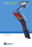
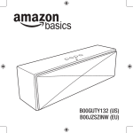
™
User Guide
ENGLISH
FRANÇAIS
1
22
Preface
About this guide
This guide provides basic operating instructions for the RD7000 receiver and transmitter.
Please read this guide in its entirety before attempting to operate the RD7000.
This guide is intended as a portable reference only. For detailed instructions, please
refer to the RD7000 operation manual, which is available for download from
www.radiodetection.com. To download the manual go to the Library section, which
is accessible via the menu; next go to Cable and Pipe Locators and then select User
Manuals and click the RD7000 Operation Manual link.
The online User Manual library also contains links to the Centros™ Manager manual.
Copyright statement
Copyright 2008 Radiodetection Ltd - SPX Corporation. All rights reserved.
Radiodetection is a subsidiary of SPX Corporation.
SPX and Radiodetection are trademarks of Radiodetection Ltd. and SPX Corporation.
Due to a policy of continued development, we reserve the right to alter or amend any
published specification without notice.
Copyright 2008 Radiodetection Ltd - SPX Corporation.
This document is protected by copyright and may not be copied, reproduced,
transmitted, modified or used, in whole or in part, without the prior written consent of
Radiodetection Ltd.
Trademarks
RD7000, RD8000, RD4000, flexitrax, SurverCERT, StrikeAlert, SideStep and eCAL are
trademarks of Radiodetection Ltd.
Important notices
When reporting any problems to your Radiodetection Dealer or Supplier it is important to
quote the unit serial number and the purchase date.
WARNING! This equipment is NOT approved for use in areas where hazardous
gases may be present.
WARNING! When using the transmitter, switch off the unit and disconnect
cables before removing the battery pack.
Reduce audio level before using the earpiece.
Batteries should be disposed of in accordance with your company’s work practice, and/
or any relevant laws or guidelines in your country.
This instrument, or family of instruments, will not be permanently damaged by
reasonable electrostatic discharge and has been tested in accordance with IEC 801-2.
However, in extreme cases temporary malfunction may occur. If this happens, switch off,
wait and switch on again. If the instrument still malfunctions, disconnect the batteries for
FCC and Industry Canada statements
This device complies with part 15 of the FCC Rules. Operation is subject to the following
conditions: (1) This device may not cause harmful interference, and (2) this device must
accept any interference received, including interference that may cause undesired
operation.
Changes or modifications not expressly approved by the party responsible for
compliance could void the user’s authority to operate the equipment. To comply with the
FCC RD explore compliance requirements, this device and its antenna must not be colocated or operated in conjunction with any other antenna or transmitter.
Training
Radiodetection provides training services for most Radiodetection products. Our
qualified instructors will train equipment operators or other personnel at your preferred
location or at Radiodetection headquarters. For more information go to
www.radiodetection.com or contact your local Radiodetection representative.
ENGLISH
DEUTSCH
WARNING! The RD7000 will detect almost all buried conductors but there are
some objects that do not radiate any detectable signal. The RD7000, or any other
electromagnetic locator, cannot detect these objects so proceed with caution.
There are also some live cables which the RD7000 will not be able to detect in
Power mode. The RD7000 does not indicate whether a signal is from a single
cable or from several in close proximity.
Español
five seconds and then reinstall and switch the unit on.
The receiver and transmitter are designed so that they do not require regular calibration.
However, as with all safety equipment, it is recommended that they are serviced at least
once a year either at Radiodetection or an approved repair center.
FRANÇAIS
Service and Maintenance
NEDERLANDS
Italiano
Radiodetection products, including this user guide, are under continuous development
and are subject to change without notice. Go to www.radiodetection.com or contact
your local Radiodetection representative for the latest information regarding the RD7000
or any Radiodetection product.
RD7000 receiver
2
1
3
4
5
8
6
7
8
15
14
10
11
9
12
13
14
16
17
23
24
18
19
20
21
22
Keypad.
2.
LCD.
3.
Battery compartment.
.
Accessory slot.
.
Headphone jack.
20. Operating mode indicator.
21. Null / Peak / Single Mode icon:
Indicates antenna selection.
22. Sonde icon: Indicates that the
signal source is from a sonde.
Receiver keypad
Power key: Switches the unit on
and off. Opens the receiver menu.
7.
ƒ key: Selects frequency. Closes
submenu.
8.
Up and down arrows: Adjusts the
signal gain. Scrolls through the
menu options.
.
Antenna key: Toggles peak and
null (PL and TL only) modes.
Open submenu. Prolonged
keypress toggles between depth
or current display on the LCD.
2. Current / depth indicator.
Español
.
23. Line icon: Indicates that the signal
source is from a line.
DEUTSCH
1.
19. A-Frame icon: Indicates when the
A-Frame is connected.
ENGLISH
Receiver features
Receiver screen icons
FRANÇAIS
10. Indicates the signal strength and
peak marker.
11. Signal strength: Numeric indication
of signal strength.
12. Peak arrows: Indicates the
location of the line relative to the
receiver.
13. Battery icon: Indicates the battery
level.
Italiano
14. Volume icon: Displays the volume
level.
15. Fault-Find arrows (PL and TL only)
16. Radio Mode: Indicates when
Radio Mode is active.
NEDERLANDS
17. Power Mode: Indicates when
Power Mode is active.
18. Accessory indicator: Indicates
when an accessory is connected.
Tx1, Tx3 and Tx10 transmitters
1
2
3
4
6
5
7
10
11
6
12
17
18
8
19
13
14
15
16
9
20
Keypad.
2.
LCD.
3.
Removable accessory tray.
17. Voltage warning indicator:
Indicates that the transmitter is
outputting potentially hazardous
voltage levels.
Transmitter keypad
Power key: Switches the unit on
and off. Opens the transmitter
menu.
.
ƒ key: Selects frequency. Menu
navigation key.
.
Up and down arrows: Adjusts the
output signal. Scrolls through the
menu options.
7.
Measure key: Toggles
measurement display between
volts, current and impedance.
Note: displayed measurements are
based on the currently selected
mode or the attached accessory, if
applicable. Opens a submenu.
18. Volume icon: Displays the volume
level.
19. Pairing icon (Tx3B and Tx10B
only). For use with RD8000
receivers only.
20. Bluetooth® icon (Tx3B and Tx10B
only). For use with RD8000
receivers only.
Español
.
ENGLISH
1.
16. CD Mode indicator: Indicates
that the transmitter is in Current
Direction Mode.
DEUTSCH
Transmitter features
8.
Battery icon: Indicates the battery
level.
.
Alphanumeric description of
selected operation mode.
FRANÇAIS
Transmitter screen icons
10. Standby icon: Appears when the
transmitter is in Standby Mode.
11. Output level: Displays transmitter
output power.
Italiano
12. Clamp icon: Indicates when a
clamp is connected.
13. DC icon: Appears when the
transmitter is powered from a DC
source.
NEDERLANDS
14. Induction indicator: Appears when
the transmitter is in Induction
Mode.
15. A-Frame: Indicates when the
transmitter is in Fault-Find Mode.
Before you begin
IMPORTANT! Please read this section before you attempt to operate the RD7000!
Starting the system
The receiver and transmitter are battery powered. Install good quality D-cell NiMH or
Alkaline batteries into the receiver and transmitter battery compartments. Alternatively,
you can power the transmitter from a mains or vehicle power source using a
Radiodetection supplied adapter.
To switch the receiver or the transmitter on, press and hold the keypad Power Key for
two seconds.
NOTE: Once the system is switched on, pressing the Power Key momentarily will
activate the receiver or transmitter menu.
Shutting down
To switch the receiver or the transmitter off, press and hold the
key for two seconds.
System setup
It is important that you set up the system according to your personal preferences and
operating requirements before you conduct your first survey. You can set the system up
using the RD7000 menu as described below.
Before changing settings, ensure the receiver or transmitter is switched on by pressing
the keypad Power Key for two seconds.
Power / mains frequency
Select the correct frequency (50 or 60Hz) for your country or region’s national power
supply. To change power frequency on the transmitter and the receiver:
1.
Press the
the menu.
key momentarily to enter
2.
Scroll to the POWER option using the arrow keys.
3.
Press the
.
Scroll up or down using the
.
Press the
key to accept your selection and return to the main menu.
.
Press the
key to return to the main operation screen.
key to enter the POWER submenu.
or
10
arrows to select the correct frequency.
To select your preferred menu language:
1.
Press the
key momentarily to enter the menu.
2.
Scroll to the LANG option using the arrow keys.
3.
Press the
.
Scroll up or down using the
.
Press the
key to accept your selection and return to the main menu.
.
Press the
key to return to the main operation screen.
on the transmitter) to enter the LANG submenu.
or
arrows to select your preferred language.
Units (receiver only)
DEUTSCH
key (
ENGLISH
Language
The RD7000 allows you to work in Metric or Imperial (US customary) units. To select
your preferred units of measurement:
Press the
key momentarily to enter the menu.
2.
Scroll to the UNIT option using the arrow keys.
3.
Press the
.
Scroll up or down using the
.
Press the
key to accept your selection and return to the main menu.
.
Press the
key to return to the main operation screen.
key to enter the UNIT submenu.
or
arrows to select Metric or Imperial units.
Español
1.
The RD7000 receiver and transmitter support both NiMH or ALK batteries. It is important
that you set the system to match the currently installed battery type to ensure optimal
performance and correct battery level indication. To set your battery type:
1.
Press the
key momentarily to enter the menu.
2.
Scroll to the BATT option using the
3.
Press the
.
Scroll up or down to select the correct battery type.
.
Press the
key to accept your selection and return to the main menu.
.
Press the
key to return to the main operation screen.
or
arrows.
on the transmitter) to enter the BATT submenu.
NEDERLANDS
The RD7000 is now ready to use.
Italiano
key (
FRANÇAIS
Battery
11
Using the menu
The RD7000 receiver and transmitter menus allow you to select or change system
options. Once entered, the menu is navigated using the arrow keys. Navigation is
consistent on both the transmitter and the receiver. When in the menu, most on-screen
icons will temporarily disappear and the menu options will appear in the bottom left-hand
corner of the LCD. Note that when browsing the receiver menu, the
and
keys act
as left and right arrows. When browsing the transmitter menu the
and
keys act as
left and right arrows. The right arrow enters a submenu and the left arrow returns to the
previous menu.
Note: When you select an option and press the Left arrow, the option will be enabled
automatically.
To navigate the receiver menu:
1.
First power up the receiver.
2.
Press the
3.
Use the
.
Press the
key to enter the option’s submenu.
.
Press the
key to return to the previous level.
.
Press the
key to return to the main operation screen.
key to enter the menu.
or
arrows to scroll through the menu options.
Receiver menu options
• VOL: Adjust the speaker volume from 0 (mute) to 3 (loudest).
• UNIT: Choose metric or imperial units.
• LANG: Select your preferred system language.
• POWER: Set national power frequency: 50 or 60Hz.
• FREQ: Enable or disable individual frequencies.
• ALERT: Enable or disable StrikeAlert™.
• BATT: Set battery type. NiMH or ALK.
• ANT: Enable or disable any antenna mode with the exception of Peak, where
present on your locator.
12
1.
First power up the transmitter.
2.
Press the
3.
Use the
.
Press the
key to enter the option’s submenu.
.
Press the
key to return to the previous level or exit the menu.
.
Press the
key to return to the main operation screen.
key to enter the menu.
arrows to scroll through the menu options.
Transmitter menu options
• VOL: Adjust the speaker volume from 0 (mute) to 3 (loudest).
DEUTSCH
or
ENGLISH
To navigate the transmitter menu:
• BT: Enable, disable or pair Bluetooth® connections (Tx3B and Tx10B only).
• MAX V: Set the output voltage.
• MODEL: Specify the model of your RD7000 receiver.
• BATT: Set battery type. NiMH or ALK.
• OPT F: Enable or disable SideStepauto™.
• LANG: Select the transmitter system language.
Español
• MAX P: Select a specific maximum output wattage.
• BOOST: Boost transmitter output for a specified period of time (in minutes).
NEDERLANDS
Italiano
FRANÇAIS
• FREQ: Enable or disable individual frequencies.
13
Locating pipes and cables
Passive Frequencies
Passive frequency detection takes advantage of signals that are already present on
buried metallic conductors. The RD7000 supports two types of passive frequencies:
power and radio signals. You can detect these frequencies without the aid of
the transmitter.
Active Frequencies
Active frequencies are applied direct to the pipe or cable using the transmitter. The
transmitter can apply a signal using two methods: induction and direct connection.
Induction
The transmitter is placed on the ground over or near the survey area. You select the
appropriate frequency. The transmitter will then induce the signal indiscriminately to any
nearby metallic conductors. In induction mode, using higher frequencies is generally
recommended as they are inducted easier onto nearby conductors.
Direct connection
In direct connection, you connect the transmitter directly to the pipe or cable you wish to
survey. The transmitter will then apply a discreet signal to the line, which you can locate
using the receiver. This method provides the best signal on an individual line and enables
the use of lower frequencies, which can be traced for longer distances.
Connecting the transmitter to a pipe or line requires the use of a direct connection lead
or clamp and a ground stake to complete the circuit.
WARNING! Direct connection to live wires is POTENTIALLY LETHAL.
Direct connections should be attempted by fully qualified personnel only!
Signal clamps
A signal clamp can apply a signal to a live line without breaking the connection. Signal
clamps are connected to the transmitter’s accessory socket. Radiodetection supplies
a range of signal clamps to suit most applications. Note that the RD7000 is fully
compatible with the RD4000 range of signal clamps.
Stethoscopes
At times, it may not be possible to use a clamp around a cable because of congestion
or inaccessibility. A stethoscope antenna should be used in place of a clamp to identify
cables.
Radiodetection supplies a range of stethoscopes to suit most applications. As with
signal clamps RD7000 is fully compatible with the RD4000 range of stethoscopes.
To use a stethoscope, connect it to the receiver’s accessory socket. The receiver will
automatically detect the device and filter out location modes that are irrelevant.
14
Sondes are battery powered transmitters that are useful for tracking
non-metallic pipes. The RD7000 PL, DL and TL can detect a range of sonde
frequencies, including those transmitted by flexisondes and the P350 flexitrax™ crawler.
ENGLISH
Locating sondes
Using accessories
Both the transmitter and receiver are compatible with a wide range of accessories,
including all RD4000 accessories. Use clamps to help apply a signal to pipeline or live
wire. Use an A-Frame to provide the RD7000 PL and TL receiver with advanced faultfinding capabilities.
NEDERLANDS
Italiano
When an accessory is connected, the receiver or transmitter will instantly recognize it
and will enable the mode appropriate to the accessory. For example, attaching an AFrame to the RD7000 PL or TL receiver will automatically switch the receiver to fault-find
mode and limit the number of available frequencies to those that are compatible with the
A-Frame. The LCD will also display an icon of the accessory and will remove any nonessential icons from the screen.
Español
The RD7000 TL and PL have the ability to detect cable faults accurately using an
accessory A-Frame. Fault-finding works by detecting signal to ground bleeding caused
by damaged cable sheaths. For a detailed guide to fault-finding, please refer to the
RD7000 operation manual.
FRANÇAIS
Fault-finding
DEUTSCH
For a detailed guide on locating sondes, please refer to the RD7000 Operation Manual
15
Centros™ Manager and eCAL™
eCAL makes it easy to validate your RD8000 or RD7000 receiver against its original
factory calibration. eCAL is bundled with the Centros Manager application suite and is
available as a free download from www.radiodetection.com. eCAL runs on laptop and
desktop computers with Microsoft Windows XP or Vista and requires one free USB port
to connect the receiver to the computer.
Before you can install Centros Manager, you must first register your receiver for the free
extended 3-year warranty at www.radiodetection.com/extendedwarranty. To use eCAL,
you must also purchase a validation key from
www.radiodetection.com/ecal.
Installing Centros Manager
1.
Download Centros Manager application bundle from
www.radiodetection.com to your computer.
2.
Close all applications on your PC, including your internet browser.
3.
Extract the files within the bundle using WinZip or a similar compressed file
manager.
.
Open the folder containing the extracted files and double click setup.exe. An
install wizard will load to help guide you through the rest of the process. Click
Next to continue and follow the on-screen prompts.
.
Once the installation process finishes, click Finish to exit the wizard.
Validating a receiver for the first time
1.
Make sure you have purchased a validation key before continuing.
2.
Connect your receiver to your computer using the supplied USB cable. On the
receiver, the USB port is located inside the battery compartment.
3.
Ensure the receiver is switched on before continuing with the firmware upgrade.
.
Open eCAL – Validation from the Windows Start Menu.
.
If you have previously loaded a validation key, the unit manager window will
display list of any RD8000 or RD7000 receiver for which you have purchased a
validation key.
.
Click the Load Validation Key icon on the toolbar.
7.
Copy and paste your validation key from your validation email into the Add
Validation Key dialogue box and click Add.
8.
Expand the tree viewer for the receiver you wish to validate by clicking the
Expand tree icon on the toolbar. eCAL will display a list of purchased Validation
Keys and the device’s Calibration History.
16
For more information about Centros Manager and eCAL, please refer to the Centros
Manager Operation Manual, which is available for download from
www.radiodetection.com.
Upgrading your RD7000
As part of our continuous product improvement strategy, Radiodetection
will release new firmware for the RD7000 and RD8000 system from time to time.
Upgrading your receiver’s firmware will improve performance, stability and may include
new features. This firmware is available free of charge. To receive notification of new
firmware releases, users should first register for extended warranty.
To register for extended warranty go to: www.radiodetection.com/extendedwarranty
When new firmware is available, registered users will receive notification automatically
via email
ENGLISH
10. Click the Calibrate Unit icon on the toolbar. eCAL will now validate the receiver
against the original factory calibration. Do not disconnect the receiver until this
process is complete.
DEUTSCH
Check that your new key appears under the Key List in the unit manager. The
key will be identifiable by the date you added it. The key will expire one week
from that date.
Español
.
To get more information about firmware upgrades go to:
www.radiodetection.com/firmwareupgrades
All RD8000 and RD7000 family products have a 1 year warranty. Users can extend the
warranty on all RD7000 and RD8000 receivers and transmitters to 3 years by registering.
Registration is free and entitles the user to free firmware upgrades.
FRANÇAIS
Extended Warranty
To be eligible, customers must register within 3 months of purchase.
When new firmware is released, registered users will receive a notification email that links
to the new firmware download page on the Radiodetection website. The email will also
contain instructions on how to download the firmware and upgrade your RD8000 or
RD7000 system.
Italiano
Upon registration customers will receive confirmation of registration by email. The email
will include a Download key required for firmware upgrades of your RD7000 or RD8000
products using Centros™ Manager.
NEDERLANDS
To register for extended warranty go to: www.radiodetection.com/extendedwarranty
17
Warranty
Subject to the conditions set out herein, Radiodetection Limited expressly and
exclusively provides the following warranty to original end user buyers of Radiodetection
products. Radiodetection products includes Radiodetection, Pearpoint, Telespec,
Bicotest, Riser Bond, Dielectric, Mark Products and Warren G-V brands. Radiodetection
hereby warrants that its products shall be free from defects in material and workmanship
for one year starting from point of sale to end customer. Extensions of this warranty
period are available where the same terms and conditions apply.
Product families include:
• Cable & Pipeline Location
• Trenchless
• Pipeline Integrity
• Pipeline Video Inspection • Ground Penetrating Radar
• Water Leak Detectors
• Cable Test
• Cable Dryers
To register for an extended warranty (3 years) go to:
www.radiodetection.com/extendedwarranty
Statement of warranty conditions
The sole and exclusive warranty for any
Radiodetection product found to be
defective is repair or replacement of the
defective product at Radiodetection’s
sole discretion. Repaired parts or
replacement products will be provided
by Radiodetection on an exchange basis
and will be either new or refurbished to be
functionally equivalent to new.
name and dealer’s name) within the
warranty period. This warranty covers
only the hardware components of the
Radiodetection product. Data storage
media or accessories must be removed
prior to submission of the product for
warranty service.
Radiodetection will not be responsible
for loss or erasure of data storage media
or accessories. Radiodetection is not
responsible for transportation costs and
risks associated with transportation of
the product. The existence of a defect
shall be determined by Radiodetection in
accordance with procedures established by
Radiodetection.
In the event this exclusive remedy is
deemed to have failed of its essential
purpose, Radiodetection’s liability shall
not exceed the purchase price of the
Radiodetection product. In no event will
Radiodetection be liable for any direct,
indirect, special, incidental, consequential
or punitive damages (including lost profit)
whether based on warranty, contract, tort
or any other legal theory.
This warranty is in lieu of any other
warranty, express or implied, including
any implied warranty of merchantability or
fitness for a particular purpose.
Warranty services will be provided only
with the original invoice or sales receipt
(indicating the date of purchase, model
18
c.
damage or defects caused by use,
operation or treatment of the product
inconsistent with its intended use
d.
damage or changes to the product as
a result of:
i.
viii. repair or attempted repair
by persons who are not
Radiodetection warranted and
certified repair houses
ix. adjustments or adaptations
without Radiodetection’s prior
written consent, including:
misuse, including: - treatment
resulting in physical, cosmetic or
surface damage or changes to
the product or damage to liquid
crystal displays
ii.
failure to install or use the product
for its normal purpose or in
accordance with Radiodetection
instructions on installation or use
iii.
failure to maintain the product in
accordance with Radiodetection
instructions on proper
maintenance
x.
upgrading the product
beyond specifications or
features described in the
instruction manual, or
ii.
modifications to the product
to conform it to national
or local technical or safety
standards in countries other
than those for which the
product was specifically
designed and manufactured
neglect e.g. opening of cases
where there are no user
replaceable parts
xi. accidents, fire, liquids, chemicals,
other substances, flooding,
vibrations, excessive heat,
improper ventilation, power
surges, excess or incorrect
supply or input voltage, radiation,
electrostatic discharges including
lighting, other external forces
and impacts.
iv. installation or use of the product
in a manner inconsistent with
the technical or safety laws or
standards in the country where it
is installed or used
v.
i.
virus infections or use of the
product with software not
provided with the product or
incorrectly installed software
NEDERLANDS
vi. the condition of or defects in
systems with which the product
is used or incorporated except
other ‘Radiodetection products’
designed to be used with the
product
ENGLISH
consumables (components that
are expected to require periodic
replacement during the lifetime of a
product such as non-rechargeable
batteries, bulbs, etc.)
DEUTSCH
b.
Español
periodic maintenance and repair or
parts replacement due to wear
and tear
FRANÇAIS
a.
Italiano
vii. use of the product with
accessories, peripheral equipment
and other products of a type,
condition and standard other than
prescribed by Radiodetection
This warranty does not cover:
19
Notes
20
NEDERLANDS
Italiano
FRANÇAIS
Español
DEUTSCH
ENGLISH
Notes
21
Préface
A propos de ce guide
Ce guide décline les opérations de base du RD7000 (Récepteur et générateur). Merci de
le lire attentivement avant toute utilisation.
La bibliothèque de guides utilisateurs en ligne comporte également le manuel Centros™
Manager.
Propriété intellectuelle
Radiodetection Ltd Marque déposée 2008 – SPX Corporation Tous droits réservés.
Radiodetection est une filiale de SPX.
SPX et Radiodetection sont des marques déposées de Radiodetection Ltd et de SPX
Corporation. Pour des considérations de développement constant, nous nous réservons
le droit de modifier sans préavis toute spécification publiée.
Radiodetection Ltd Marque déposée 2008 – SPX Corporation.
Ce document est protégé par les droits d’édition et ne peut être copié, reproduit,
transmis modifié ou utilisé tout ou partie sans l’accord écrit de Radiodetection Ltd.
Marques déposées
RD7000, RD8000, RD4000, flexitrax, SurverCERT, StrikeAlert, SideStep et eCAL sont
des marques déposées de Radiodetection Ltd.
Remarques importantes
Merci de noter le numéro de série ainsi que la date d’acquisition de l’appareil en cas de
problème technique.
IMPORTANT: Cet équipement n’est pas autorisé à fonctionner en
environnement explosif.
IMPORTANT : Lorsque vous utilisez le générateur, veillez à éteindre l’unité et
débrancher les câbles avant de retirer les piles.
Réduisez le volume sonore avant d’utiliser l’oreillette.
Les piles doivent être recyclées selon les règles en vigueur en France.
Cet appareil a été testé en conformité avec la norme IEC 801-2. Il n’est pas sensible
à une décharge électrostatique raisonnable. Toutefois et de façon exceptionnelle, des
dysfonctionnements peuvent se produire. Dans ce cas éteignez, attendez puis rallumez
à nouveau. Si l’appareil continue de mal fonctionner, déconnectez la batterie cinq
secondes puis reconnectez-la et ré-allumez l’appareil.
22
IMPORTANT: Le RD7000 peut détecter pratiquement tous les réseaux enterrés
mais certains réseaux n’émettent pas de signaux détectables. Le RD7000, pas
plus qu’aucun autre détecteur électromagnétique, ne peut les localiser aussi
veillez à procéder toujours avec précaution. Certains câbles sous tension peuvent
ne pas être détectés par le RD7000. En effet, le RD7000 ne précise pas si un signal
électromagnétique provient d’un câble unique ou de plusieurs.
Cet appareil répond à l’article 15 des règles du FCC. La manipulation est soumise aux
conditions suivantes:1 Il ne doit pas générer d’interférences dangereuses. Et 2 cet
appareil doit pouvoir absorber toute interférence reçue y compris celles pouvant générer
un dysfonctionnement.
Tout changement ou modification non expressément approuvée par l’autorité
responsable pourrait annuler le droit à l’utilisation par l’utilisateur. Pour répondre
aux exigences du FCC, Radiodetection examine toutes les contraintes en matière
de compatibilité. Cet appareil et ses antennes ne doivent pas utilisés avec d’autres
détecteurs ou d’autres antennes.
Formation
Radiodetection propose des sessions de formation sur ses produits. Nos formateurs
peuvent, au choix former vos personnels sur site ou au siège de Radiodetection France
13, Grand’ Rue 76220 Neuf Marché. 02 32 89 93 60 – http://fr.radiodetecion.com.
Service et Maintenance
Le détecteur et le générateur sont conçus de sorte à ne pas nécessiter de calibrations
fréquentes. Il est toutefois recommandé de faire procéder à un contrôle une fois par an
chez Radiodetection France.
Les produits de Radiodetection, y compris ce guide utilisateur, sont en amélioration
permanente et susceptible de modification sans préavis. Appelez Radiodetection France
ou visitez www.radiodetection.fr pour trouver les dernières informations concernant
le RD7000
23
FRANÇAIS
FCC (Federal Communication Commission)
Le récepteur RD7000
2
1
3
4
5
8
6
7
8
15
14
10
11
9
12
13
14
16
17
23
24
18
19
20
21
24
22
Composantes du
récepteur
Panneau.
2.
Ecran LCD.
3.
Compartiment piles.
.
Prise accessoires.
.
Prise casque.
20. Indicateur de mode opératoire:
21. Icones Nul/Maxi/Global: Indique le
mode de réception.
22. Icone de sonde: indique que le
signal est émis par une sonde.
23. Icone de ligne: Indique le signal est
émis par un réseau conducteur.
Panneau
2. Indicateur de courant/profondeur.
.
Bouton Marche /Arrêt.
7.
Sélection de fréquences.
Fermeture de sous-menus.
8.
Ajuste le gain du signal. Fait défiler
les options d’un menu.
.
Affiche le mode de réception Maxi
& Nul (modèles PL TL).Ouvre
les sous-menus. Une pression
prolongée donne la mesure de
courant et la profondeur.
Icônes écran
10. Le niveau du signal et le maximum
du « Maxi ».
11. Puissance du signal: Valeur
numérique de la puissance du
signal.
12. Flèches: Indique la position
d’un câble/Cana par rapport au
détecteur.
13. Icone de pile: Niveau de charge
des piles.
14. Icone de volume: Niveau sonore.
15. Flèches de recherche de défaut
(PL et TL)
16. Mode Radio: Indique que le mode
radio est actif.
17. Mode 50Hz: Indique que le mode
50Hz est actif.
18. Indicateur d’accessoire: Indique
qu’un accessoire est connecté.
25
FRANÇAIS
1.
19. Indique qu’un arceau est
connecté.
Générateur Tx1, Tx3 & Tx10
1
2
3
4
6
5
7
10
11
6
12
17
18
8
19
13
14
15
16
9
20
26
Composantes du
générateur
Panneau
2.
Ecran LCD.
3.
Rangement accessoires.
17. Alerte tension : Indique que le
générateur produit une tension
potentiellement dangereuse.
Panneau
18. Icône de volume : Affiche le niveau
sonore.
.
Bouton Marche /Arrêt
.
Sélection de fréquences.
Fermeture de sous-menus.
.
Ajuste le gain du signal. Fait défiler
les options d’un menu.
7.
Affiche les mesures de tension,
de courant et d’impédance :
Note les mesures en fonction du
mode choisi ou de l’accessoire
connecté. Peut aussi ouvrir des
sous menu.
Icones d’écran
8.
Icone de piles: Niveau de charge
des piles.
.
Description alphanumérique du
mode opératoire
10. Icône de Veille. Indique que le
générateur n’émet pas.
11. Niveau de sortie : Affiche la
puissance de signal en sortie de
générateur.
12. Icône de pince : Indique qu’une
pince à champ magnétique est
raccordée.
13. Icône de courant continu :
S’affiche quand le générateur
est alimenté par une source en
courant continu.
14. Indicateur d’induction : Apparait
lorsque le générateur est en mode
induction.
15. Arceau : Indique que le générateur
est en mode Recherche de défaut.
27
19. Icone d’Appairage: (Tx3B et
Tx10B seulement) : Pour le
RD8000 seulement.
20. Icône Bluetooth® (Tx3B and
Tx10B): Pour le RD8000
seulement.
FRANÇAIS
1.
16. Indicateur Sens de courant :
Indique que le générateur est
en mode recherche de sens de
courant.
Avant de commencer
IMPORTANT! Merci de lire ce manuel avant de commencer toute utilisation.
Mise en fonctionnement du détecteur
Le récepteur et le générateur sont alimentés par des piles. Veillez à utiliser des piles
alcalines ou des accus NiMH de qualité. En outre, vous pouvez alimenter le générateur
par une batterie de voiture en utilisant un adaptateur fourni par Radiodetection.
Pour allumer le récepteur ou le générateur, appuyez sur
pendant 2 secondes.
NOTE: Une fois l’appareil allumé, le fait de ré-appuyer sur
l’appareil (récepteur ou générateur).
affiche le menu de
Mise hors tension
Pour éteindre l’appareil appuyez sur
pendant 2 secondes.
Paramétrage du matériel
Il est important que vous paramétriez le matériel en fonction de vos préférences ou de
vos exigences de travail. Vous pouvez paramétrer l’ensemble RD7000 comme décrit
plus loin.
Avant de commencer à changer le paramétrage, assurez-vous que l’appareil est allumé.
En appuyant sur
pendant 2 secondes.
Mode 50 Hz / Fréquences
Sélectionnez le mode 50 Hz pour la France. Pour modifier ce mode sur le récepteur et le
générateur.
1.
Appuyez sur
pour afficher le menu.
2.
Faites défiler les options avec
3.
Appuyez sur
.
Faites défiler les options avec
.
Appuyez sur
pour valider votre sélection et retourner au menu.
.
Appuyez sur
pour afficher le menu principal.
et
.
pour entrer dans les sous-menus.
et
pour sélectionner la fréquence voulue.
Langage
Pour sélectionner un langage:
1.
Appuyez sur
pour afficher le menu principal.
2.
Faites défiler les options avec
3.
Appuyez sur
.
Faites défiler les options avec
.
Appuyez sur
et
jusqu’à « LANG »
pour entrer dans le sous-menu « LANG ».
et
pour sélectionner la langue choisie.
pour valider votre sélection et retourner au menu.
28
.
Appuyez sur
pour afficher le menu principal.
Unités (Seulement pour les récepteurs)
Le récepteur RD7000 vous permet de travailler en mesures métriques ou impériales.
1.
Appuyez sur
pour afficher le menu principal.
2.
Faites défiler les options avec
3.
Appuyez sur
.
Faites défiler les options avec
.
Appuyez sur
pour valider votre sélection et retourner au menu.
.
Appuyez sur
pour afficher le menu principal.
et
jusqu’à « UNIT »
et
pour sélectionner l’unité choisie.
Alimentation
Le récepteur RD7000 et le générateur sont alimentés par des piles alcalines ou des
accus NiMH. Il est important que vous utilisiez ce type d’alimentation pour obtenir des
performances optimales. Pour paramétrer le type d’alimentation :
1.
Appuyez sur
2.
Faites défiler les options avec
pour afficher le menu principal.
3.
Appuyez sur
.
Faites défiler les options avec
.
Appuyez sur
pour valider votre sélection et retourner au menu.
.
Appuyez sur
pour afficher le menu principal.
et
jusqu’à « BATT »
pour entrer dans le sous-menu « BATT »
et
Le RD7000 est maintenant prêt à l’emploi.
29
pour sélectionner le type d’alimentation.
FRANÇAIS
pour entrer dans le sous-menu « UNIT »
Utilisez le Menu
Les menus des récepteurs RD7000 et des générateurs vous offrent la possibilité de
paramétrer vos appareils. Vous naviguez dans les menus par les flèches. La navigation
est la même pour le récepteur et pour le générateur. Une fois à l’intérieur du menu,
la plupart des icones disparaissent et les options du menu apparaissent dans le coin
inférieur gauche de l’écran. Note : remarquez que lorsque vous faites défiler le menu du
récepteur la touche
et la touche
se comportent comme flèches gauche et droite.
La flèche droite vous donne accès au sous-menu,
remonte au menu précédent.
Note: Lorsque vous sélectionnez une option et pressez
, celle-ci sera validée.
Pour naviguer dans le menu du récepteur
1.
Allumez le récepteur
2.
Appuyez sur
3.
Faites défiler les options avec
.
Appuyez sur
pour entrer dans le sous-menu.
.
Appuyez sur
pour valider votre sélection.
.
Appuyez sur
pour afficher le menu principal.
pour afficher le menu principal.
et
.
Options du menu récepteur
• VOL: Ajuste le volume sonore du récepteur.
• UNIT: Choix entre système métrique et impérial.
• LANG: Sélectionnez une langue.
• POWER: Mode 50 Hz ou 60 Hz.
• FREQ: Active ou désactive des fréquences.
• ALERT: Active ou désactive le StrikeAlert™.
• BATT: Sélectionne les piles Alcalines ou les accus NiMH.
• ANT: Active ou désactive les modes de réception à l’exception du mode Maxi.
30
Pour naviguer dans le menu Générateur
1.
Allumez le générateur
2.
Appuyez sur
3.
Faites défiler les options avec
.
Appuyez sur
pour entrer dans le sous-menu.
.
Appuyez sur
pour remonter au niveau précédent.
.
Appuyez sur
pour afficher le menu principal.
pour afficher le menu principal.
.
Options du menu générateur
• VOL: Ajuste le volume sonore du générateur.
• BT: Active, désactive, appaire les connexions Bluetooth® (Seulement pour les
RD8000 Tx3B and Tx10B).
• MAX V: Règle la tension de sortie.
• MODEL: Affiche le modèle de RD7000.
• MAX P: Affiche la puissance maximum de sortie (watts).
• BATT: Sélectionne les piles Alcalines ou les accus NiMH.
• OPT F: Active ou désactive le SideStepauto™.
• LANG: Sélectionnez une langue.
• BOOST: Pousse le signal de sortie à son maximum pour une durée choisie (minutes).
• FREQ: Active ou désactive des fréquences.
31
FRANÇAIS
et
Détecter des câbles et des
canalisations
Fréquences passives
La détection des fréquences passives tire parti de l’émission de signaux
électromagnétiques présents dans les conducteurs métalliques. Les RD7000 utilisent
deux modes de détections passives: 50 Hz et Radio. Vous pouvez détecter ces
fréquences sans l’utilisation d’un générateur.
Fréquences actives
Les fréquences actives permettent d’injecter le signal d’un générateur directement dans
les câbles ou canalisations. Le générateur peut fonctionner selon deux modes: induction
ou raccordement directe.
Induction
Le générateur est placé sur ou près de la zone à étudier. Vous sélectionnez la fréquence
appropriée. Le générateur va alors émettre un signal qui sera induit sur tout conducteur
métallique se trouvant à proximité. En mode induction, il est généralement recommandé
d’utiliser des fréquences hautes.
Raccordement direct
Le raccordement direct exige l’utilisation d’une pince émettrice ou de cordons de
raccordent et d’un piquet de terre pour fermer le circuit. En raccordement direct vous
raccordez directement le générateur sur le câble ou la canalisation. Le générateur va
alors injecter un signal tout au long de ce conducteur que vous pourrez alors localiser à
l’aide du récepteur. Cette méthode offre les meilleurs résultats sur des lignes individuelles
et privilégie l’utilisation de basses fréquences qui se propagent sur de plus
longues distances.
ATTENTION: Se raccorder à des câbles sous tension présente un danger de
mort. Ces raccordements directs doivent être effectués exclusivement par des
personnels habilitées à travailler sous tension.
Pince émettrice
Une pince émettrice émet un signal le long d’un câble sous tension de manière
non destructrice. Les pinces sont connectées au port accessoire du générateur.
Radiodetection fournit une large gamme d’accessoires qui correspondent à la plupart
des applications. Notez que les RD7000 sont totalement compatibles avec la gamme
des accessoires des RD4000 (sauf cordon allume-cigares).
32
Antennes stéthoscopes
Sondes
Les sondes sont des générateurs alimentés par piles, utiles pour le traçage des réseaux
non-métalliques. Les récepteurs RD7000 PL, DL et TL peuvent détecter une large
gamme de fréquences incluant celles transmises par les flexisondes et la caméra
tractée P350.
Pour plus d’informations concernant les sondes, veuillez vous référer au manuel
d’utilisation des sondes.
Recherche de défauts
Les RD7000 TL et PL peuvent effectuer de la recherche de défauts de câbles en
utilisant un arceau. La recherche de défaut fonctionne sur le principe de fuite à la terre
consécutive à un endommagement du blindage du câble. Pour plus d’information
concernant la recherche de défauts, merci de vous reporter au manuel opérationnel
du RD7000.
Utiliser les accessoires
Le détecteur et le générateur sont compatibles avec une large gamme d’accessoires,
incluant les accessoires du RD4000 (sauf cordon allume cigare).
Lors du raccordement d’un accessoire sur le récepteur ou un générateur, l’appareil va
détecter la connexion et se mettre automatiquement en configuration appropriée. Par
exemple, si vous connectez un arceau sur le récepteur (RD7000 TL et PL), celui-ci se
mettra automatiquement en mode de recherche de défauts et limitera de lui-même le
panel de fréquences disponibles à celles utilisables en recherche de défauts. L’écran
LCD affichera également l’icône de l’accessoire et effacera toutes icones superflues.
33
FRANÇAIS
En cas d’impossibilité d’utiliser une pince réceptrice (Exiguïté des regards,
inaccessibilité), il convient d’employer une antenne stéthoscope. Radiodetection fournit
une large gamme d’antenne stéthoscopes. Les RD7000 sont totalement compatibles
avec la gamme d’antennes stéthoscopes des R4000. Pour utiliser une antenne
stéthoscope, connectez-la au port accessoire du récepteur. Le récepteur détectera
automatiquement l’accessoire et désactivera les modes de détection non concernés.
Centros™ Manager et eCAL™
eCAL permet la validation du calibrage usine des récepteurs RD7000 et RD8000. eCAL
fait partie de la plateforme Centros Manager et est librement téléchargeable depuis le
site www.radiodetection.com. eCAL fonctionne sur ordinateur fixe ou portable sous
OS Windows XP et VISTA. Il requiert un port USB pour relier le récepteur à l’ordinateur.
Avant d’installer Centros Manager, vous devez tout d’abord enregistrer votre détecteur à
l’extension de garantie de 3 ans (gratuit) en allant sur
www.radiodetection.com/extendedwarranty. Pour utiliser eCAL vous devez également
acheter une clef de validation à www.radiodetection.com/ecal.
Installer Centros Manager
1.
Téléchargez l’application Centros Manager depuis le site
www.radiodetection.com.
2.
Fermez toutes les applications de votre ordinateur, y compris le
navigateur internet.
3.
Décompressez tous les fichiers (WinZip,…)
.
Ouvrez le répertoire comprenant les fichiers extraits et double cliquez sur
setup.exe.
.
Le logiciel d’installation va se charger.
.
Centros Manager va maintenant être installé à l’emplacement spécifié. Cliquez
sur « Finish » pour terminer l’installation et quittez l’application.
Valider un récepteur pour la première fois
1.
Assurez-vous que vous disposez de la clef de mise à jour avant de poursuivre.
2.
Raccordez votre récepteur au PC par un cordon USB fourni. Sur le récepteur,
l’interface USB est située sous la trappe piles.
3.
Ouvrez le menu eCAL –– Validation « Upgrade » depuis le menu de démarrage
de Windows.
.
Ouvrez la fenêtre de Certification en cliquant sur l’icône cerclée.
.
Si, au contraire, vous avez déjà effectué des validations dans le passé, la
fenêtre du « unit manager » en affichera la liste.
.
Appelez la page de saisie de clef en cliquant sur l’icône clef.
7.
Copiez la clef dans le mail de Radiodetection et collez-la dans la fenêtre
ci-dessous.
8.
Assurez-vous que la date du jour apparait bien dans la liste. La validité de la clef
expirera une semaine plus tard.
.
Lancez la calibration en cliquant sur l’icône cerclée. Ne débranchez pas le
détecteur avant la fin de la calibration.
34
NOTE: La première fois que vous utiliserez eCAL, la fenêtre Unit Manager sera vide.
Vous devrez charger une clef de validation avant de poursuivre comme décrit à
l’étape 6.
Une fois le processus terminé, une nouvelle ligne apparait à la suite de l’historique
de calibration. Désormais, vous pouvez voir, imprimer ou sauvegarder le certificat de
validation. Pour ce faire :
1. Cliquez sur la dernière ligne de l’historique de calibration.
2.
Lancez l’édition du certificat de calibration en cliquant sur l’icône cerclée
3.
Pour sauvegarder le certificat, -> Fichier -> Sauvegarder sous. Les certificats
sont sauvegardés sous format HTML à l’emplacement de votre choix. Vous
pouvez ensuite visualiser les certificats sous n’importe quel navigateur internet.
.
Pour imprimer un certificat -> Fichier -> Imprimer et suivez les indications de
votre boite de dialogue.
NOTE: En dépit du fait que les clefs de validation ne soient valables qu’une semaine,
vous pouvez afficher, imprimer ou sauvegarder les certificats librement. A la
différence des clefs de validation, les certificats ne sont pas assujettis à une date
d’expiration.
Mettre le RD7000 à niveau
Radiodetection poursuit la mise à jour permanente de ses produits. A ce titre, des
mises à jours et des miro code seront régulièrement et gracieusement mises à votre
disposition. Pour être informé de ces mises à jour par email, il suffit de vous inscrire à
l’extension de garantie de 3 ans (gratuite) au lien
www.radiodetection.com/extendedwarranty.
Par la suite, à chaque nouvelle version du firmware , vous recevrez un email de
Radiodetection vous prévenant de sa mise à disposition.
Pour darantage d’informations concernant les firmwares, allez à
www.radiodetection.com/firmwareupgrades.
Extension de garantie
Tous les produits RD7000/RD8000 bénéficient d’une garantie Pièces et Mains
d’œuvre d’un an. Les utilisateurs peuvent étendre cette garantie à 3 ans en s’inscrivant
gratuitement. Cet enregistrement offre de surcroît le libre accès aux mises à jour
firmware. Pour être éligibles, les utilisateurs doivent s’inscrire dans les trois mois
qui suivent l’achat. Après enregistrement, les utilisateurs reçoivent confirmation
de leurs inscriptions par email. Cet email contiendra une clef indispensable pour le
téléchargement des mises à jour de firmware.
Pour vous enregistrer: www.radiodetection.com/extendedwarranty.
35
FRANÇAIS
Sauvegarder et imprimer les certificats
Garantie
Les conditions de garanties décrites ci-dessous s’appliquent exclusivement aux clients
finaux premiers acquéreurs des produits de Radiodetection. Par produits Radiodetection
s’entendent les produits de marques Radiodetection, Pearpoint, Telespec, Bicotest,
Riser Bond, Dielectric, Mark Products et Warren G-V.
Radiodetection garantit que ses équipements sont exempts de tout défaut de pièces
et de main d’œuvre pour une durée d’un an à compter de la vente du produit. Les
extensions de garantie s’appliquent dans les mêmes conditions.
Les familles de produits comprennent:
• La détection de câbles et de canalisations.
• Contrôle d’enrobage de pipelines.
• Détection de défauts sur câbles.
• Matériels de suivit d’outils de forage
dirigé.
• Caméra d’Inspection vidéo des
canalisations.
• Détecteurs de fuite d’eau.
• Radar de sol.
Pour vous inscrire à l’extension de garantie de 3 ans, allez à:
www.radiodetection.com/extendedwarranty.
Conditions de garantie
La seule et unique garantie offerte par
Radiodetection en cas de défaillance de
l’un de ses appareils est la réparation ou
le remplacement de la pièce en question à
l’entière discrétion de Radiodetection.
Le remplacement ou la réparation des
pièces se fera sur la base d’un retour usine
de la pièce défaillante en vue de retourner
au client une pièce fonctionnellement
équivalente à une nouvelle pièce.
de vente indiquant la date de l’achat, le
modèle du produit et le nom du vendeur et
ce, pendant la période de garantie. Cette
garantie ne couvre que les composants de
Radiodetection. Les mémoires de masse
ou accessoires doivent être retirés de la
garantie.
Radiodetection ne saurait être tenue pour
responsable de toute perte d’information
inscrite sur les mémoires de masse ou
accessoires. Radiodetection ne saurait
être tenu pour responsable des coûts
de transports ni des risques afférents.
Tout défaut ne peut être constaté que
par Radiodetection en accord avec les
procédures de Radiodetection.
Dans l’hypothèse ou cette démarche
aurait échoué, la responsabilité de
Radiodetection ne saurait excéder le
montant d’achat du produit. En aucun
cas Radiodetection ne saura être tenue
Cette garantie est en lieu et place de toute
responsable de pertes indirectes y compris
autre garantie explicite ou implicite.
les pertes d’exploitation,
La garantie jouera sur présentation de
la facture d’origine ou sur un récépissé
36
i.
a.
Maintenance périodique liée à l’usure
des pièces.
b.
Consommables.
c.
Dommages causes par un usage
non normal, dans des conditions non
normales.
d.
Dommages ou altération du produits
résultats de:
i.
Mauvaise utilisation ayant
provoqué des dégâts physiques,
esthétiques ou de revêtement ou
ayant altéré le produit ou ayant
dégradé l’écran LCD.
ii.
Mauvaise installation ou mise
en service, non conforme aux
prescriptions de Radiodetection
iii.
Mauvais entretien des
équipements, non conforme aux
prescriptions de Radiodetection
x.
Négligences, par exemple ouvrir
des compartiments normalement
interdits à l’utilisateur,
xi. Accidents, feu, liquides,
produits chimiques, vibrations
excessives, chaleur excessive,
ventilation insuffisante, surcharge
électrique, radiation, décharges
électrostatiques incluant la foudre
et autres forces externes.
iv. Installation ou exploitation de
l’appareil de manière incompatible
avec les règles de sécurité du
pays d’exploitation de l’appareil.
v.
Modifications du produit
pour le rendre conforme aux
règles de sécurité du pays
d’exploitation de l’appareil.
Infections virales du produit
par un logiciel non fourni par
Radiodetection.
vi. Le dysfonctionnement d’autres
équipements ou systèmes autres
que ceux de Radiodetection,
vii. L’usage des équipements
de Radiodetection avec des
périphériques, accessoires ou
consommables non prescrits par
Radiodetection.
viii. La réparation ou la tentative de
réparation par des personnels non
certifiées par Radiodetection.
ix. L’ajustement ou l’adaptation
sans l’accord écrit préalable de
Radiodetection incluant:
37
FRANÇAIS
Cette garantie ne couvre pas:
Notes
38
FRANÇAIS
Notes
39
America
Radiodetection
154 Portland Road, Bridgton, ME 04009, USA
Tel: +1 (207) 647 9495 Toll Free: +1 (877) 247 3797 Fax: +1 (207) 647 9496
Email: [email protected] Web: www.radiodetection.com
Pearpoint
72055 Corporate Way, Thousand Palms CA 92276, USA
Tel: +1 800 688 8094 Tel: +1 760 343 7350 Fax: +1 760 343 7351
Email: [email protected] Web: www.radiodetection.com
Radiodetection (Canada)
344 Edgeley Boulevard, Unit 34, Concord, Ontario L4K 4B7, Canada
Tel: +1 (905) 660 9995 Toll Free: +1 (800) 665 7953 Fax: +1 (905) 660 9579
Email: [email protected] Web: www.radiodetection.com
Europe
Radiodetection Ltd (UK)
Western Drive, Bristol BS14 0AF, UK
Tel: +44 (0) 117 976 7776 Fax: +44 (0) 117 976 7775
Email: [email protected] Web: www.radiodetection.com
Radiodetection (France)
13 Grande Rue, 76220, Neuf Marché, France
Tel: +33 (0) 2 32 89 93 60 Fax: +33 (0) 2 35 90 95 58
Email: [email protected] Web: http://fr.radiodetection.com
Radiodetection (Benelux)
Industriestraat 11, 7041 GD ’s-Heerenberg, Netherlands
Tel: +31 (0) 314 66 47 00 Fax: +31 (0) 314 66 41 30
Email: [email protected] Web: http://nl.radiodetection.com
Radiodetection (Germany)
Groendahlscher Weg 118, 46446 Emmerich am Rhein, Germany
Tel: +49 (0) 28 51 92 37 20 Fax: +49 (0) 28 51 92 37 520
Email: [email protected] Web: http://de.radiodetection.com
Asia-Pacific
Radiodetection (Asia-Pacific)
Room 708, CC Wu Building, 302-308 Hennessy Road, Wan Chai, Hong Kong SAR, China
Tel: +852 2110 8160 Fax: +852 2110 9681
Email: [email protected] Web: www.radiodetection.com
Radiodetection (China)
Hongfu Mansion, Room 61622, Zheng Ge Zhuang, Bei Qi Jia Town, Chang Ping District
Beijing 102209, China
Tel: +86 (0) 10 8975 5540 Fax: +86 (0) 10 8975 5640
Email: [email protected] Web: http://cn.radiodetection.com
Radiodetection (Australia)
Unit 14, 5-7 Prosperity Parade, Warriewood NSW 2102, Australia
Tel: +61 (0) 2 9979 8555 Fax: +61 (0) 2 9979 7733
Email: [email protected] Web: www.radiodetection.com
www.radiodetection.com
Radiodetection products are under continuous development and are subject to change, we
reserve the right to alter or amend any published specification without notice.
Copyright 2008 Radiodetection Ltd. - SPX Corporation. All rights reserved. Radiodetection Ltd.
is a subsidiary of SPX Corporation.
90/UG078INT/01