1
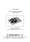
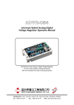
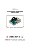
CH1812 CH1824
Automatic Battery Charger User’s Guide
Headquarters : No.3, Lane 201, Chien Fu ST., Chyan Jenn Dist., Kaohsiung, TAIWAN
Tel : + 886-7-8121771
Fax : + 886-7-8121775
URL : http://www.kutai.com.tw
1. INTRODUCTION
AC Input Voltage
Voltage
100 / 220 VAC ±10% Single Phase
(Adjustable)
Frequency
50 / 60Hz ± 5%
Equalize Charge Voltage
14.5VDC @ 12 VDC Charging Voltage
28.8VDC @ 24 VDC Charging Voltage
Float Charge Voltage
13.8VDC @ 12 VDC Charging Voltage
27.6VDC @ 24 VDC Charging Voltage
Rated Output Voltage
0.5 ADC ~ 20.0 ADC
Equalize Mode Voltage Adjustable Range
13.5VDC ~ 16.0VDC @ 12 VDC Charging Voltage
27.0VDC ~ 31.0VDC @ 24 VDC Charging Voltage
Float Mode Voltage Adjustable Range
13.0VDC ~ 14.5VDC @ 12 VDC Charging Voltage
25.8VDC ~ 28.0VDC @ 24 VDC Charging Voltage
Charge Mode
Equalize Charge Mode & Float Charge Mode
DC Voltage Regulation
< ± 1%
Efficiency
80% @ Full Load
Ripple Effect
±3%
Protection
Voltage Regulation, Current Limit
Short Circuit Protection
Spike protection
Reverse polarity connection of battery
Semiconductor type regulation
Operating Temperature
-10 ~ 40 °C
-20 ~ 40 °C
Dimensions
315mm L * 255mm W * 230mm H
Weight
21 kg ± 2%
Equalize Charging Time
6, 12, 24 Hours setting
2. GENERAL DESCRIPTION
These units are works by a full wave accurate
controlled thyristor and lnductive filters and
smoothing capacitors to reduce the ripple amplitude
of output. Thyristor regulation ensures low power
dissipation and generously specified components
provide for high operation efficiency.
3. FEATURES
3.1
Charges batteries with constant voltage and
current.
3.2
Charge voltage / output current limit are
adjustable.
3.7
Low ripple voltage (below ±1%).
3.8
High power efficiency (over 80%).
3.9
Separated analogue voltmeter and ammeter
indication the charging voltage and current.
4. ELECTRICAL CHARACTERISTICS
4.1
Input Voltage : 1 phase 110V/220V ±10%
50/60 Hz optional.
4.2
Output voltage for Equalize Charging :
For 12V system 13.5 VDC ~ 16.0 VDC adjustable.
For 24V system 27.0 VDC ~ 31.0 VDC adjustable.
4.3
Output voltage for Float Charging :
3.3
Float / Equalize charge mode are available.
For 12V system 13.0 VDC ~ 14.5 VDC adjustable.
3.4
6/ 12 /24 hr timer selection for Equalized
charge mode.
For 24V system 25.8 VDC ~ 28.0 VDC adjustable.
3.5
Main input and DC output are fused by
separated 1 pole MCCB on front panel.
3.6
Protection against shorted circuit and reverse
polarity connection of battery.
4.4
Output current : 0 ~ 20 ADC adjustable.
4.5
Output Voltage Regulation : ±1%.
4.6
Power Efficiency : > 80% on full load.
4.7
Charge Mode : Float / Equalize available.
______________________________________________________________________________________
2
CH18
4.8
Protection :
Connect the output of this unit to the post of
battery carefully.
● Output current limited.
● MCCB tripped in case of over current of
main input.
● MCCB tripped in case of reverse polarity
connection of battery.
5. INSTALLATION PLACE
5.1
Avoid humid places.
5.2
Avoid environment of corrosive gas.
5.3
Do not expose it to direct sun radiation or close
a heating source.
5.4
Install it in a place that is easily accessible,
adequate ventilation and without vibrations.
5.5
Batteries generate explosive hydrogen gas,
even during normal operation.
5.6
People may injure by battery parts flying in an
explosion.
5.7
They can explode under normal operating
conditions.
5.8
Avoid Flames and Sparks Near Battery.
6. WIRING AND ADJUSTMENT
6.1
Ensure the output of the battery charger is
accords with the voltage of battery.
6.2
Ensure the wiring of the battery charger is
accords with main input voltage.
CAUTION
Terminal lug must properly and securely
crimp onto wires.
Because of the high current being carried by
these lugs.
An inadequate or improper crimp will
eventually lead to overheating of the joint.
Failure will soon follow, often with severe
damage spreading beyond the immediate
crimp joint.
6.4
Adjust 10 to expected value.
NOTE
The value must refer to the battery user’s
guide.
Over charge current will cause batteries
damaged and this is helpless to shorten
charge time.
6.5
● CH1824 Equalize charge mode is 28.8VDC.
Float charge mode is 27.8VDC.
● Unless the target battery is very old do not
change the default value.
● Main power feed in 1 and 2.
6.6
● Connect 5 and 6 with jumper wire.
6.2.2 Main Voltage is 220VAC.
● Connect 4 and 5 with jumper wire.
6.2.3 Connect main power.
● Turn power MCCB on.
● The power pilot LED and float charge LED
should illuminated.
● Voltmeter should appear default value 13.8V
(at 12V system) or 27.8V (at 24V system).
6.3
If procedure 6.2 is performed normal turn
power MCCB off.
Charge current is limited in the preset value
anytime in spite of the target batteries was fully
discharged.
The value will decrease accompanies the
battery is charged. The value approach to zero
represent the battery is nearly saturation.
● Main power feed in 1 and 2.
● Terminal 3 and 6 are null.
Factory default setting voltage are.
● CH1812 Equalize charge mode is 14.5VDC.
Float charge mode is 13.8VDC.
6.2.1 Main Voltage is 110VAC. (Figure 3)
● Connect 3 and 4 with jumper wire.
Turn power MCCB on again.
6.7
Float charge mode is effective at initial power
on.
● In case of the battery is extremely discharged
or repeat charge is needed press button 6
the equalize charge mode is effective.
● Equalize charge mode will continue to
6/12/24 hours and back to float charge mode
automatically to prevent battery overcharged.
Factory default time is 6 hours. (Figure 2)
● Turn the power MCCB off is able to break
equalize charge mode.
______________________________________________________________________________________
CH18
3
6.8
The timer of equalize charge mode is able to
changed.
Remove the metal cover of this enclosure and
jump the wire proper position can change the
timer.
6.9
When measuring the output voltage in an open
circuit, user need to parallel a 4.7KΩ~10KΩ
(1W) resistor.
Figure 2
1
2
3
4
5
6
Figure 3
7. TROUBLESHOOTING
(1) DC Voltmeter for output.
(2) DC Ammeter for output.
(3) Power LED.
(4) Equalize mode LED.
(5) Float mode LED.
(6) Equalize mode setting button.
(7) Output MCCB.
(8) Main power MCCB.
(9) Adjust VR for float charge mode
voltage.
(10) Adjust VR for output current limit.
(11) Adjust VR for equalize charge mode
voltage.
(12) Positive out terminal (red).
(13) Negative out terminal (black).
8. TROUBLESHOOTING
1. Check the voltage of the main AC source.
2. Check whether main MCCB is tripped.
No output voltage
3. Check whether the output terminal is feed to battery properly.
4. Check whether output is shorted.
5. Check whether reverse battery polarity is connected.
1. Check whether the battery is saturated.
No charge current or the
current is unable battery
properly
※
※
2. Check whether the output terminals are feed to battery properly.
3. Check whether the battery charger is accordant with target battery.
4. Check whether if battery is decayed.
5. Check whether the output MCCB is tripped.
If these steps above could not make the charger working still, Please contact with KUTAI.
Please accept our sincere apology if any modification in performance, specification or appearance is
made without prior notice.
______________________________________________________________________________________
4
CH18