1
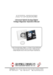
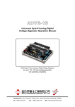
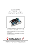
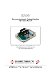
ADVR-054 Universal Hybrid Analog-Digital Voltage Regulator Operation Manual Self Excited 5 Amp Analog / Digital Voltage Regulator For shunt and auxiliary windings generators With over-excitation and lost of sensing protection Headquarters : No.3, Lane 201, Chien Fu St., Chyan Jenn Dist., Kaohsiung, TAIWAN Tel : + 886-7-8121771 Fax : + 886-7-8121775 URL : http://www.kutai.com.tw WARNING 1. Some generators even when working at high voltage are factory set to sense at lower voltages. Remember to set the DIP SW 2 to the sensing voltage not the working voltage of the generator even do sometimes it can be the same. If you have a 480/277V generator but you have the sensing wires C and A connected to 240 Volts move DIP SW 2 to ON Another example are rental units with multi-voltage output with a switches for Y, YY, Delta & ZZ output, but sensing is always at 240V from T7 and T9 even though the generator is running sometimes at 480/277V. 2. Before using a Megger or a Withstand Voltage Tester, removes the wires connecting to the AVR to prevent high voltage damage to the regulator. SECTION 1 : SPECIFICATION Sensing Input (A, C) Average Reading Voltage 170 260 Vac @ 220 Vac, 1 phase 2 wires 340 520 Vac @ 440 Vac, 1 phase 2 wires 220/440 Vac, DIP switch setting Frequency 50 / 60 Hz, DIP switch setting Power Input (B, C) Voltage 100 300 Vac, 1 phase 2 wires Frequency 40 60 Hz Excitation Output (F+, F-) Voltage 63 Vdc @ 220 Vac power input, 1 phase Continuous 5A Max.90 Vdc 7A 10 secs. Resistance Min. 15 ohms Max. 100 ohms Fuse Spec. Slow blow 5 x 20mm S505-5A External Voltage Adjustment (EXT.VR) Max. +/- 3.5% @ 1K ohm 1 watt potentiometer Voltage Regulation Less than +/- 0.5% ( with 4% engine governing ) Build Up Voltage 5 Vac 25 Hz residual volts at power input terminal Soft Start Ramp Time 3 sec. +/- 10% Response Time Less than 20 milliseconds Static Power Dissipation Max.8 watts Under Frequency Protection (Factory Presets) 50 Hz system presets knee point at 45 Hz 60 Hz system presets knee point at 55 Hz Over Excitation Voltage Protection Set point 78 Vdc +/- 6% @ power input 220 Vac Time delay 5 secs. This function can be turned off. Voltage Thermal Drift Less than 3% at temperature range -40 to +70 ˚C Under-Frequency Knee Point Thermal Drift Less than +/- 0.1 Hz at -40 to +70 ˚C Environment Operation Temperature Storage Temperature Relative Humidity Vibration -40 to +70 ˚C -40 to +85 ˚C Max. 95% 5 Gs @ 60 Hz Dimensions 121.0 (L) x 81.0 (W) x 44.5 (H) mm 4.76 (L) x 3.19 (W) x 1.75 (H) inch Weight 270 g +/- 2% 0.6 lb +/- 2% EMI Suppression Internal electromagnetic interference filtering ___________________________________________________________________________________________ 2 ADVR-054 SECTION 2 : APPEARANCE / DIMENSIONS / INSTALLATION DRAWING 50.0 [1.96"] M4 L25 8.5 [0.33"] 27.0 [1.06"] 44.5 [1.75"] Unit : mm [inch] Figure 1 Outline Drawing ATTENTION 1. Only qualified technicians should install and operate the AVR. 2. The voltage regulator may be installed at any suitable location on the generator set (dimensions are shown in Figure 1). It is recommended that unit is mounted vertically with the green resistors on the regulator upwards to achieve the best cooling effect. 3. All AC voltage sensing readings are average value only. ___________________________________________________________________________________________ ADVR-054 3 SECTION 3 : DIP SWITCH SETTINGS, LED INDICATORS AND ADJUSTMENTS Over Excitation (O/E) LED When the excitation voltage is greater than 35% of input power voltage, the LED will lit after 5 sec. If the DIP switch SW3 set at OFF then it will also shut off excitation output at the same time. - + S F 40 (50) 51 (61) U/F LED Under Frequency Protection status. DIP Switches System Freqency SW1 ON:50 Hz, OFF:60 Hz Sensing Input SW2 ON:220V, OFF:440V O/E Protection SW3 ON:Disable, ON:Enable VOLT Voltage Adjustment The adjustment range is set by SW2. STAB Stability Setting With No Load, slowly turn the STAB counterclockwise until voltage becomes unstable then turn clockwise about 1/5 turn. U/F Under Frequency Protection 50 Hz system preset at 45 Hz, 60 Hz system preset at 55 Hz, To change the setting, see the Adjustment Step 3. ADVR-054 EXT.VR Ext Potentiometer, 1K ohm 1W. Keep shorted when not in use. C:Sensing Input and Power Input terminals F+ , F-:Connect to generator excitation field. A:Sensing Input terminal A to C: 170 – 520 Vac B:Power Input terminal B to C: always less than 300 Vac ADJUSTMENTS AFTER GENERATOR IS STARTED : 1. First, turn VOLT and STAB trimpots fully counterclockwise before starting the generator. Set the engine governor to 50 or 60 Hz. Start the generator and wait till it reaches rated speed. Now slowly turn VOLT trimpot clockwise to increase the working voltage. (If you use an external potentiometer, set it to the center position). Keep EXT. VR shorted when not in use. 2. Next, slowly adjusting the STAB trimpot etting (clockwise), this change the response time of the AVR to changing loads. If the setting is too high the voltage is unstable but if set too low the response is sluggish. We recommend using an analog DC voltage meter on F, F+ and adjust STAB for the lowest amount of voltage fluctuation (needle movement). 3. Last, Under Frequency (U/F) adjustment. (The U/F is Factory preset and needs no adjustments) put in rare applications. Use the U/F LED as a guide. When this LED is ON the circuit is operational turning off the regulators output. To recalibrate, adjust the generator speed to the new U/F kneel point, usually 5 Hz under rated speed (Hz) then set the U/F trim-pot to the point at which the U/F LED just changes from off to on rated speed (Hz) then set the U/F trimpot to the point at which the U/F LED just changes from off to on. Adjustment range for 50Hz system is 40 to 51 Hz. For 60 Hz system the range is 50 to 61 Hz. ___________________________________________________________________________________________ 4 ADVR-054 SECTION 4 : CONNECTION DIAGRAMS N N R R G ~ S T G ~ S T Field Field 1000 Ohm EXT. VR 1000 Ohm EXT. VR ADVR-054 ADVR-054 Refer to Section 3 for DIP Switch setting. Refer to Section 3 for DIP Switch setting. Figure 3 170 260V sensing connection (Option 1) Figure 4 170 260V sensing connection (Option 2) N N R R G ~ S T G ~ S T Field Field 1000 Ohm EXT. VR Aux.winding ADVR-054 ADVR-054 Refer to Section 3 for DIP Switch setting. Figure 5 1000 Ohm EXT. VR 340 520V sensing connection Refer to Section 3 for DIP Switch setting. Figure 6 Auxiliary Winding connection ※ Package include 4 pcs of M4 L25 Round head bolts and 2 pcs of terminal jumpers. ※ Use only replacement fuses specified in this user manual. ※ Appearance and specifications of products are subject to change for improvement without prior notice. ___________________________________________________________________________________________ ADVR-054 5