1
Sunny Boy and Sunny Mini Central
Solar Inverters for Photovoltaic Plants
Operating Instructions
Version 1.5
SB_SMC-11:FE3206
TBE-ALL
SMA Technologie AG
Table of Contents
Table of Contents
1
1.1
1.2
1.3
Foreword . . . . . . . . . . . . . . . . . . . . . . . . . . . . . . .
Target group . . . . . . . . . . . . . . . . . . . . . . . . . . . . .
Explanation of the symbols used: . . . . . . . . . . . . . . .
Identification of the inverter . . . . . . . . . . . . . . . . . . .
2
Safety instructions . . . . . . . . . . . . . . . . . . . . . . . 11
3
3.1
3.2
Unit description . . . . . . . . . . . . . . . . . . . . . . . . . 13
Appropriate usage . . . . . . . . . . . . . . . . . . . . . . . . 13
Construction of inverters . . . . . . . . . . . . . . . . . . . . 14
3.2.1
3.2.2
3.2.3
Principle of the string inverter. . . . . . . . . . . . . . . . . . . . . . . . . .15
Principle of the Multi-String inverter . . . . . . . . . . . . . . . . . . . . .17
Connection area . . . . . . . . . . . . . . . . . . . . . . . . . . . . . . . . . .18
4
4.1
4.2
4.3
4.4
Operating modes of the inverter
Normal operation. . . . . . . . . . . . .
Critical faulty operation. . . . . . . . .
Non-critical faulty operation. . . . . .
Description of the operating modes
4.4.1
4.4.2
4.4.3
4.4.4
4.4.5
4.4.6
4.4.7
4.4.8
4.4.9
4.4.10
4.4.11
4.4.12
4.4.13
4.4.14
Overnight shutdown . . . . . . . . . . . . . . . . . . . . . . . . . . . . . . . .23
Initialization. . . . . . . . . . . . . . . . . . . . . . . . . . . . . . . . . . . . . .23
Waiting, grid monitoring . . . . . . . . . . . . . . . . . . . . . . . . . . . . .24
Working mode . . . . . . . . . . . . . . . . . . . . . . . . . . . . . . . . . . .24
Stop . . . . . . . . . . . . . . . . . . . . . . . . . . . . . . . . . . . . . . . . . . .25
Permanent disable . . . . . . . . . . . . . . . . . . . . . . . . . . . . . . . . .25
Derating . . . . . . . . . . . . . . . . . . . . . . . . . . . . . . . . . . . . . . . .26
Insulation fault or defective varistor . . . . . . . . . . . . . . . . . . . . .27
Defective DC input . . . . . . . . . . . . . . . . . . . . . . . . . . . . . . . . .27
Grid fault . . . . . . . . . . . . . . . . . . . . . . . . . . . . . . . . . . . . . . .28
Grid impedance. . . . . . . . . . . . . . . . . . . . . . . . . . . . . . . . . . .29
Input voltage (PV generator) too high. . . . . . . . . . . . . . . . . . . .30
Device fault . . . . . . . . . . . . . . . . . . . . . . . . . . . . . . . . . . . . . .31
Leakage current too high . . . . . . . . . . . . . . . . . . . . . . . . . . . .32
Operating Instructions
.
.
.
.
.
.
.
.
.
.
..
..
..
..
..
.
.
.
.
.
.
.
.
.
.
.
.
.
.
.
..
..
..
..
..
SB_SMC-11:FE3206
.
.
.
.
.
.
.
.
.
.
.
.
.
.
.
7
7
8
9
21
22
22
23
23
Page 3
SMA Technologie AG
Table of Contents
4.4.15
Changes in differential current . . . . . . . . . . . . . . . . . . . . . . . . .33
5
5.1
5.2
5.3
Information on the display. . . . . . .
Switching on the display illumination. .
Display messages in the startup phase
Display messages during operation . .
5.3.1
5.3.2
5.3.3
Fault displays. . . . . . . . . . . . . . . . . . . . . . . . . . . . . . . . . . . . .36
DC overvoltage . . . . . . . . . . . . . . . . . . . . . . . . . . . . . . . . . . .37
SMA Power Balancer . . . . . . . . . . . . . . . . . . . . . . . . . . . . . . .37
6
Maintenance and care . . . . . . . . . . . . . . . . . . . . 39
7
7.1
System monitoring . . . . . . . . . . . . . . . . . . . . . . . 41
Sunny Data . . . . . . . . . . . . . . . . . . . . . . . . . . . . . 41
7.1.1
7.1.2
7.1.3
Sunny Data via Powerline . . . . . . . . . . . . . . . . . . . . . . . . . . . .42
Sunny Data over RS232 . . . . . . . . . . . . . . . . . . . . . . . . . . . . .42
Sunny Data over RS485 . . . . . . . . . . . . . . . . . . . . . . . . . . . . .43
7.2
Sunny Beam . . . . . . . . . . . . . . . . . . . . . . . . . . . . 44
7.2.1
Sunny Data Control over Sunny Beam . . . . . . . . . . . . . . . . . . .44
7.3
7.4
7.5
7.6
7.7
7.8
Sunny
Sunny
Sunny
Sunny
Sunny
Sunny
.
.
.
.
.
.
45
45
46
47
48
48
8
8.1
8.2
8.3
Measurement channels and messages. . . . . . . .
Measurment channels . . . . . . . . . . . . . . . . . . . . . .
Status messages . . . . . . . . . . . . . . . . . . . . . . . . . .
Operating parameters. . . . . . . . . . . . . . . . . . . . . .
49
49
52
55
8.3.1
Non-modifiable parameters. . . . . . . . . . . . . . . . . . . . . . . . . . .60
8.4
8.5
Fault messages . . . . . . . . . . . . . . . . . . . . . . . . . . . 61
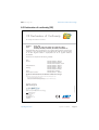
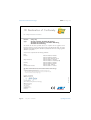
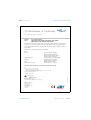
Declaration of conformity (CE) . . . . . . . . . . . . . . . . 69
Page 4
SB_SMC-11:FE3206
Boy Control Light
Boy Control . . . .
Boy Control Plus .
Data Control . . .
WebBox . . . . . .
Portal . . . . . . . .
......
......
......
......
......
......
..
..
..
..
..
..
.
.
.
.
.
.
.
.
.
.
.
.
..
..
..
..
..
..
..
..
..
..
.
.
.
.
.
.
.
.
.
.
.
.
.
.
.
.
.
.
.
.
.
.
.
.
.
.
.
.
.
.
..
..
..
..
..
..
..
..
..
..
.
.
.
.
.
.
.
.
.
.
.
.
.
.
.
.
.
.
.
.
.
.
.
.
35
35
35
36
Operating Instructions
SMA Technologie AG
8.6
Clean report of findings. . . . . . . . . . . . . . . . . . . . . 72
9
Glossary . . . . . . . . . . . . . . . . . . . . . . . . . . . . . . 75
10
Contact. . . . . . . . . . . . . . . . . . . . . . . . . . . . . . . . 79
Operating Instructions
SB_SMC-11:FE3206
Page 5
SMA Technologie AG
Page 6
SB_SMC-11:FE3206
Operating Instructions
SMA Technologie AG
Foreword
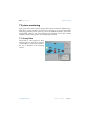
1 Foreword
Warning!
The Sunny Boy and Sunny Mini Central may only be installed by trained
specialists. Installation engineers must be approved by the local energy
supplier.
Please read the installation manual thoroughly. All prescribed safety
regulations, the technical connection requirements (TCR) of the local
energy supplier and all VDEW regulations must be adhered to.
With the purchase of a Sunny Boy or Sunny Mini Central, you have decided on a
technically mature device, which is currently the most advanced modular PV system
technology available for connecting photovoltaic systems to the grid. SMA inverters
distinguish themselves particularly by means of their high levels of efficiency and
reliability. These inverters comply with all the VDEW (Verband der Elektrizitätswirtschaft
– German Electricity Industry Association) regulations for the connection and parallel
operation of electrical power units to the low-voltage grid of the electricity supply
company. This also encompasses the regulations of the German Professional
Association for Precision Engineering and Electrotechnology relating to "Automatic
switching of electrical power units" and/or DIN VDE 0126. In addition to this, the
inverter conforms to the electromagnetic tolerance regulations and the low-voltage
regulations of the relevant combined European norms, as confirmed in the CE
conformity declaration (see chapter 8.5 "Declaration of conformity (CE)" (Page 69)).
1.1 Target group
This documentation is intended for the operator of the system. The documentation
provided here primarily covers such topics that are of interest when operating the
inverter. In addition to explanations of the operational methods of the device, advice
as to data capture and analysis is also provided.
Information relating to the installation and commission of the inverter should be taken
from the installation manual delivered with the device. The installation manual also
contains detailed device-specific technical data.
Operating Instructions
SB_SMC-11:FE3206
Page 7
SMA Technologie AG
Foreword
1.2 Explanation of the symbols used:
To ensure optimum use of these instructions, please note the following explanation of
symbols used.
This symbol identifies an example.
This symbol identifies a notice where failure to follow the advice will make the
procedure or operation more difficult.
This symbol indicates a fact that when not observed could result in
damage to components or danger to persons. Please read these sections
especially carefully.
Page 8
SB_SMC-11:FE3206
Operating Instructions
SMA Technologie AG
Foreword
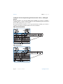
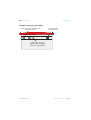
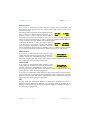
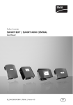
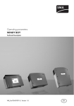
1.3 Identification of the inverter
You can identify the inverter with the aid of the type plate (see figure below). The type
plate is usually found on the right-hand side of the enclosure (when viewed from the
front). On the Sunny Boy SB 2800i and the Multi-String devices, the type plate is found
on the underside of the device. The type plate contains information regarding the
device type, serial number, device-specific key data, the CE mark and SMA contact
information.
The following is an example of a Sunny Boy SB 700 type plate.
Device Type
Operating Instructions
Serial Number
SB_SMC-11:FE3206
Page 9
SMA Technologie AG
Foreword
Certificate for the independent grid disconnection device, "SMA grid
guard"
On the type plate, you can also identify which standard your inverter is certified is
complying with, i.e. which certificate applies for the independent grid disconnection
device "SMA grid guard" in your inverter.
The following written information on your type plate denotes whether your inverter is
certified in accordance with DIN VDE 0126 or other standards.
DIN VDE 0126 (04.99)
DIN VDE 0126-1-1
Page 10
SB_SMC-11:FE3206
Operating Instructions
SMA Technologie AG
Safety instructions
2 Safety instructions
Opening of the inverter, and any
•
electrical installation,
•
repair or
•
modification
of the inverter may only be performed by qualified electrical personnel.
Even when no external voltage is present, the device can still contain high
voltages.
The temperature of individual parts of the enclosure of the inverter - in
particular the temperature of the heatsink(s) - can reach a temperature of
over 60°C in normal operation. There is the danger of burn injury when
these parts are touched!
Operating Instructions
SB_SMC-11:FE3206
Page 11
Safety instructions
SMA Technologie AG
Page 12
Operating Instructions
SB_SMC-11:FE3206
SMA Technologie AG
Unit description
3 Unit description
3.1 Appropriate usage
The Sunny Boy / Sunny Mini Central allows photovoltaic solar energy to be converted
and fed into a 220 - 240 V 50 Hz low voltage grid. Some SMA inverters can also be
operated on a 60 Hz grid. More precise information on this subject and on your device
can be found in the installation manual. The operational limits specified in the
installation manual for the particular inverter must be observed.
Do not use the Sunny Boy / Sunny Mini Central for purposes other than those
indicated in this chapter. Other modes of usage can cause the device to be
damaged or to become completely inoperable, and can mean that the guarantee
no longer applies. If you have questions regarding the proper usage of the Sunny
Boy or Sunny Mini Central, contact the Sunny Boy hotline.
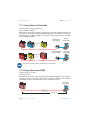
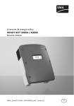
Principle of a grid-connected solar energy system with a string inverter
Photovoltaic
modules
Sunny Boy
Electricity grid
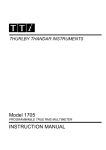
Principle of a grid-connected solar energy system with a Multi-String
inverter
String A
String B
Photovoltaic
modules
Operating Instructions
Sunny Boy
Multi-String
Electricity grid
SB_SMC-11:FE3206
Page 13
SMA Technologie AG
Unit description
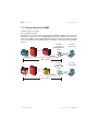
Principle of a grid-connected solar energy system with Sunny Mini
Central inverters
Distributor
Electricity grid
Photovoltaic
modules
Sunny Mini
Central
3.2 Construction of inverters
An attractive, functional design is one of the major objectives of the entire SMA product
range. The basic configuration of the Sunny Boy / Sunny Mini Central includes the
status display consisting of three LEDs, which has proven to be highly reliable, as well
as a plain text display. A deliberate decision has been made to avoid the use of
controls on the device.
Fine tuning of the device to align it with the solar energy system is not necessary. If this
is specifically desired, because of special system conditions, then one of the optional
communications interfaces is required. This also allows the current operational data to
be recorded on a PC using a special program. This is described in more detail in
chapter 7 "System monitoring" (Page 41).
Page 14
SB_SMC-11:FE3206
Operating Instructions
SMA Technologie AG
Unit description
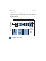
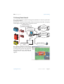
3.2.1 Principle of the string inverter
The string inverter is used to connect a small number of series-connected solar modules
(strings) to the public grid. A larger solar generator can also be constructed from a
number of individual strings, with each having its own string inverter. The energy is then
combined on the AC side.
Block circuit diagram of a string inverter with transformer
Sunny Boy SB 1100 enclosure IP65 (outdoor installation possible)
SMA
grid guard
Bridge
Transformer
AC plug
DC input with 2 x 2 connectors
MPP
tracking
Overvoltage
protection
Ground fault
monitoring
Thermally
monitored
varistors
Display
(IP65)
Optional
communications interface:
RS232,
RS485,
Powerline,
radio
The Sunny Boy SB 2800i is an indoor inverter. It is protection class IP21 and is
only suitable for installation indoors.
Operating Instructions
SB_SMC-11:FE3206
Page 15
SMA Technologie AG
Unit description
Block circuit diagram of a string inverter without transformer
Sunny Boy SB 2100TL enclosure IP65 (outdoor installation possible)
Step-up
converter
SMA grid guard
Bridge
AC plug
DC input with 2 x 2 connectors
MPP
tracking
Overvoltage
protection:
Ground fault
monitoring
Page 16
Thermally
monitored
varistors
SB_SMC-11:FE3206
Display
(IP65)
Leakage
current
measurement
Optional
communications interface: RS232,
RS485,
Powerline,
radio
Operating Instructions
SMA Technologie AG
Unit description
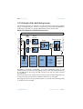
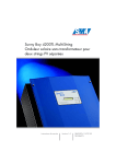
3.2.2 Principle of the Multi-String inverter
The Multi-String inverter is conceived for use with photovoltaic systems having different
strings. As illustrated below, each DC connection of the Sunny Boy SB 5000TL HC
Multi-String is allocated to a separate MPP (Maximum Power Point) tracker.
Block circuit diagram of a Multi-String inverter
Sunny Boy SB 5000TL HC enclosure IP65 (outdoor installation possible)
Step-up
converter
SMA grid guard
Bridge
MPP
tracking
Step-up
converter
Overvoltage
protection:
Ground
fault
monitoring
Thermally
monitored
varistors
Display
(IP65)
Leakage
current
measurement
AC output with terminals
DC input with 3 x 2 connectors
MPP
tracking
Optional
communications interface: RS232,
RS485,
Powerline,
radio
Depending on the device configuration, up to three independent strings of a PV
generator can be connected to a Multi-String inverter. Since each individual input has
its own MPP tracker, the strings may differ in respect to the type of modules used and
their alignment.
Even the specified current, voltage and power ratings of the individual strings may vary,
as long as the limits specified in the installation manual are not exceeded.
The energy from the two or three individual inputs is converted and fed into the grid by
a combined inverter assembly.
Operating Instructions
SB_SMC-11:FE3206
Page 17
SMA Technologie AG
Unit description
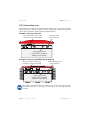
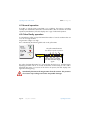
3.2.3 Connection area
All connections are made on the underside of the inverter. The AC connection is made
with an AC plug, or else the connection cable is fed through a cable opening in the
inverter and connected to the AC terminals inside the device.
Example: Sunny Boy SB 1100
Plug and socket connector for
connection of the solar modules
AC plug for the
grid connection
Opening for optional
communication via RS232,
RS485 or radio (PG16)
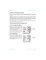
Example: Sunny Boy SB 5000TL HC Multi-String
Plug and socket connector for
connection of the solar modules
Cable opening for the
grid connection
Opening for optional
communication via RS232,
RS485 or radio (PG16)
The number and alignment of DC connections varies for the various device types.
The devices have one to four plug connector pairs for connecting the solar
modules.
Page 18
SB_SMC-11:FE3206
Operating Instructions
SMA Technologie AG
Unit description
Example: Sunny Boy SB 1100LV
Cable opening for connection of
the solar modules
AC plug for the
grid connection
Opening for optional
communication via RS232,
RS485 or radio (PG16)
Operating Instructions
SB_SMC-11:FE3206
Page 19
Unit description
SMA Technologie AG
Page 20
Operating Instructions
SB_SMC-11:FE3206
SMA Technologie AG
Operating modes of the inverter
4 Operating modes of the inverter
The operating mode is displayed using three light-emitting diodes (LEDs) on the cover
of the inverter, and also via the integrated display (see chapter 5 "Information on the
display" (Page 35)). To allow the device to signal its operating mode via the 3
integrated LEDs, the inverter must be connected to the DC side of the system. There must
be enough solar energy present, so that the inverter has adequate DC voltage.
Especially in the first year of operation, the operator of the system should pay
attention to this display, at various times of day and under various conditions of
solar irradiation. This allows the detection of hidden faults caused by the
orientation or installation of the system, and the assurance that the PV system is
operating in accordance with the regulations.
A complete description of the possible LED displays can be found in chapter 4.4
"Description of the operating modes" (Page 23). These can be split into three
categories, as described below.
Operating Instructions
SB_SMC-11:FE3206
Page 21
SMA Technologie AG
Operating modes of the inverter
4.1 Normal operation
If no LED, or only the green control LED is on, or blinking, the inverter is operating
normally. The simultaneous illumination of all three LEDs is also an indication of normal
operation ("Initialization"). All other displays are a sign of abnormal operation.
4.2 Critical faulty operation
A comprehensive safety concept has limited the number of critical conditions that can
occur to one single situation:
PV generator voltage is too high.
This is indicated by the following blink-code on the yellow LED:
(green)
(red)
The yellow LED illuminates
four times in quick succession.
(yellow)
LED on
LED off
The message is repeated
three times and then begins
again.
The yellow fault LED illuminates for 5 seconds when the fault occurs, and then begins
displaying the blink code of: 3 seconds off and then 4 times briefly on. This code is
displayed three times in succession. If the fault is still present, the fault display starts
again from the beginning.
Immediately disconnect the PV generator from the inverter. The presence
of excessive input voltage can lead to irreparable damage!
Page 22
SB_SMC-11:FE3206
Operating Instructions
SMA Technologie AG
Operating modes of the inverter
4.3 Non-critical faulty operation
All other fault codes indicate some form of faulty operation, which is not usually
dangerous to people or equipment, but which should nevertheless be investigated and
corrected.
Despite all precautions, it is possible that other faults may occur that cannot be
displayed (e.g. failure of the status display). In order to detect such faults, the operator
of the system should use the explanations in the following chapter to check the
plausibility of the displayed mode (e.g. an illuminated green LED in the middle of the
night indicates a fault, as well as no illuminated LED on a sunny day).
Further detailed diagnoses are possible using the communications options detailed in
chapter 7 "System monitoring" (Page 41) .
4.4 Description of the operating modes
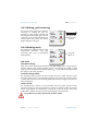
4.4.1 Overnight shutdown
The inverter is in the so-called overnight
shutdown mode. This situation occurs
when the inverter's input voltage is too low
for feeding the grid and for satisfying the
on-board power requirements.
If this operating mode occurs during the
day on a sunny day, have the PV voltage
checked by an installation engineer.
(green)
(red)
All LEDs
are off.
(yellow)
4.4.2 Initialization
The inverter's on-board computer is
presently in the initialization phase. The
on-board energy supply is present, but
there is insufficient energy for feeding the
grid and data communication is also not
currently possible.
Operating Instructions
(green)
(red)
All LEDs
are on.
(yellow)
SB_SMC-11:FE3206
Page 23
SMA Technologie AG
Operating modes of the inverter
4.4.3 Waiting, grid monitoring
The inverter checks if the initial conditions
necessary for feeding the grid are
satisfied (e.g. start voltage, start time) and
then begins monitoring the grid. The PV
voltage must reach the specified minimum
value at least once, before the inverter
begins feeding into the grid.
(green)
(red)
(yellow)
The green LED
blinks once per
second.
4.4.4 Working mode
The inverter has passed the self-tests of the
measurement electronics and grid
monitoring, and is now in normal gridfeed operation.
(green)
(red)
The green
LED is on.
(yellow)
MPP mode
(standard setting):
Here, the inverter automatically determines the MPP voltage of the solar generator,
which is defined in the internal regulation system as the desired PV voltage. In MPP
mode, the point of maximum feed-in performance PAC is set by adjustment of the desired
PV voltage on the solar generator.
Constant voltage mode:
The operating mode "V-Const" can be manually set by the system operator via the
Sunny Boy Control or the Sunny Data PC program. In "V-Const" mode, the Sunny Boy
/ Sunny Mini Central uses an externally defined desired PV voltage as the basis for
internal regulation.
Turbine mode:
The operating mode "Turbine" can be manually set by the system operator via the
Sunny Boy Control or the Sunny Data PC program. In "Turbine" mode, the inverter
follows a pre-defined V/I characteristic curve for the conversion of DC current from
wind turbines. Details are to be found in the "Windy Boy" documentation.
PV systems must not be operated in "Turbine" mode!
Page 24
SB_SMC-11:FE3206
Operating Instructions
SMA Technologie AG
Operating modes of the inverter
4.4.5 Stop
The inverter is in Stop mode. Among other
functions, the measurement electronics
are calibrated and then finally, the device
switches to "Waiting" mode.
The "Stop" mode can also be manually set
by the system operator via the Sunny Boy
Control or the Sunny Data PC program. In
this case, the inverter remains in "Stop"
mode until a new operating mode ("MPP"
mode, "V-Const" mode) has been set.
(green)
(red)
(yellow)
The green LED
blinks three times
per second.
4.4.6 Permanent disable
In the event of a recurring fault, the
inverter switches from "Working" mode to
"Permanent restriction of operation"
mode.
A fault may exist that cannot be resolved
on-site. You can attempt to remove the
fault with the aid of a communication
interface
and
the
corresponding
communication product (e.g. PC with
Sunny Data or Sunny Boy Control). If this
is unsuccessful, consult the Sunny Boy
hotline (chapter 10 "Contact" (Page 79))
to discuss further action to solve the
problem.
Operating Instructions
(green)
(red)
(yellow)
The yellow LED
is continuously
on.
SB_SMC-11:FE3206
Page 25
SMA Technologie AG
Operating modes of the inverter
4.4.7 Derating
The "Derating" operating mode is a
normal operating mode which may occur
occasionally and can have several
causes:
Temperature derating
(green)
(red)
(yellow)
The green LED
goes out briefly
once per
second.
The temperature monitoring of the inverter
has reduced the output performance to
prevent the device from overheating. The
inverter enters the "Temperature derating"
mode. If the Sunny Boy / Sunny Mini Central switches to this operating mode often,
you should check the heat dissipation and install the inverter in a more suitable position
with better ventilation. If the unit is a Sunny Mini Central, Sunny Boy SB 3800, SB 3300
or SB 2800i, check whether the fans are dirty.
Fan cleaning is described in the respective installation manual.
Current derating
Due to the module type or the generator output and wiring, the PV-side input current
exceeds the maximum possible input current. The inverter switches to the "Current
derating" mode in order to protect itself against overload. Check the system design.
Output derating
This operating mode only occurs in systems which are operated using the Sunny Mini
Central with the integrated SMA Power Balancer in the "PowerGuard" setting. If outputs
of over 5 kVA are to be fed in one phase, it is usually necessary to construct a 3-phase
system from 3 identical inverters. This is imperative to avoid an unbalanced load
between phases L1 - L3. If one of the three inverters ceases to feed into the grid, the
other two inverters reduce their maximum output to 5 kVA. Check the devices'
operational conditions, and remove the fault. More information on the SMA Power
Balancer can be found in the Sunny Mini Central's installation manual.
Page 26
SB_SMC-11:FE3206
Operating Instructions
SMA Technologie AG
Operating modes of the inverter
4.4.8 Insulation fault or defective varistor
The red LED on the Sunny Boy / Sunny
Mini Central is continuously on. With this
blink code, it is not relevant if the green or
yellow LEDs shine or blink. A grounding
fault exists or one of the thermally
monitored varistors on the DC input is
defective as a result of overvoltage or
ageing. In this event, only devices with
transformers (without "TL" in the device
name) continue to feed electricity.
(green)
not relevant
(red)
The red LED is
continuously
on.
(yellow)
not relevant
Consult trained electrical personnel to correct the fault. Fault removal
instructions can be found in the inverter's installation manual.
4.4.9 Defective DC input
Sunny Boy Multi-String
The red LED blinks. With this blink code, it
is not relevant if the green or yellow LEDs
are on of off. At least one of the DC inputs
is defective.
(green)
(red)
not relevant
The red LED
blinks.
(yellow)
not relevant
A fault has occurred which can no longer be resolved on-site. Consult SMA
(see chapter 10 "Contact" (Page 79)) to discuss further action.
Operating Instructions
SB_SMC-11:FE3206
Page 27
SMA Technologie AG
Operating modes of the inverter
4.4.10 Grid fault
(green)
(red)
The yellow LED illuminates
twice in quick succession.
(yellow)
LED on
LED off
The code is
repeated three
times and then
begins again.
The yellow fault LED illuminates for 5 seconds when the fault occurs, and then begins
displaying the blink code of: 3 seconds off, then twice briefly on. This code is displayed
three times in succession. If the fault is still present, the fault display starts again from the
beginning.
With this message, the inverter indicates a grid fault, which can have the following
causes:
•
Low grid voltage
(UAC < "Uac-Min")
•
High grid voltage
(UAC > "Uac-Max")
•
Low grid frequency
(fAC < "Fac-Min")
•
High grid frequency
(fAC > "Fac-Max")
•
A change in grid frequency ("dFac")
•
Faulty grid connection (e.g. N and L swapped)
•
In systems which consist of three or more Sunny Mini Centrals, the SMA Power
Balancer has detected a fault (see also chapter 5.3.3 "SMA Power Balancer"
(Page 37)).
Check if a general grid dropout has occurred (check the operation of other electrical
consumer devices), check that the fuses in the feed-in connections of the inverter are
undamaged and check if the automatic cutout is switched on.
If none of these faults can be found, have the grid connection of the Sunny
Boy / Sunny Mini Central checked by qualified electrical personnel.
Page 28
SB_SMC-11:FE3206
Operating Instructions
SMA Technologie AG
Operating modes of the inverter
4.4.11 Grid impedance
(green)
(red)
The yellow LED illuminates three
times in quick succession.
(yellow)
LED on
LED off
The code is repeated
three times, then
begins again.
The yellow fault LED illuminates for 5 seconds when the fault occurs, and then begins
displaying the blink code of: 3 seconds off, then 3 times briefly on. This code is
displayed three times in succession. If the fault is still present, the fault display starts
again from the beginning.
The inverter has detected a fault relating to an unacceptable impedance in the grid. If
the inverter frequently displays this fault during grid monitoring, the cause can be a grid
impedance that is too high. An electrician can usually assist with this problem by
increasing the cross section of the grid connection cable. Tightening the terminal clamps
on the connection cable can also help. Other measures can be taken to correct this
problem, but they require the aproval of the electricity supplier.
Operating Instructions
SB_SMC-11:FE3206
Page 29
SMA Technologie AG
Operating modes of the inverter
4.4.12 Input voltage (PV generator) too high
(green)
(red)
The yellow LED illuminates four times in
quick succession.
(yellow)
LED on
LED off
The code is repeated three
times, then begins again.
The yellow fault LED illuminates for 5 seconds when the fault occurs, and then begins
displaying the blink code of: 3 seconds off, then 4 times briefly on. This code is
displayed three times in succession. If the fault is still present, the fault display starts
again from the beginning.
The voltage of the PV generator exceeds the inverter's permissible input voltage!
Immediately disconnect the PV generator from the Sunny Boy / Sunny
Mini Central. The presence of excessive input voltage can lead to
irreparable damage!
Page 30
SB_SMC-11:FE3206
Operating Instructions
SMA Technologie AG
Operating modes of the inverter
4.4.13 Device fault
(green)
(red)
The yellow LED illuminates
five times in quick succession.
(yellow)
LED on
LED off
The code is repeated three
times, then begins again.
The yellow fault LED illuminates for 5 seconds when the fault occurs, and then begins
displaying the blink code of: 3 seconds off, then 5 times briefly on. This code is
displayed three times in succession. If the fault is still present, the fault display starts
again from the beginning.
If the device fault leads to a major reduction in normal operation, the
inverter and the entire system installation should be checked by an
electrician. You must take particular care that devices without
transformers (with "TL" in the device name) are correctly grounded!
Operating Instructions
SB_SMC-11:FE3206
Page 31
SMA Technologie AG
Operating modes of the inverter
4.4.14 Leakage current too high
(green)
(red)
The yellow LED illuminates six
times in quick succession.
(yellow)
LED on
LED off
The code is repeated three times,
then begins again.
The "Leakage current too high" fault can only occur in transformerless inverters.
Inverters without transformers can be identified by their full name; the TL in the
name stands for transformerless: e.g. Sunny Boy SB 5000TL HC Multi-String.
The yellow fault LED illuminates for 5 seconds when the fault occurs, then begins
displaying the blink code of: 3 seconds off, then 6 times briefly on. This code is
displayed three times in succession. If the fault is still present, the fault display starts
again from the beginning.
The leakage current of the inverter and the PV generator is too high. The Sunny Boy /
Sunny Mini Central immediately stops feeding the grid as soon as the limit has been
reached, then automatically resumes normal operation when the fault is no longer
present.
The leakage current is dependent on the capacity of the PV generator relative to ground
and depends equally on the type of modules and manner of installation as well as the
weather conditions. A variation of this value over time is therefore normal.
If however, the inverter frequently displays this fault, notify the installation engineer who
installed your PV system and clarify the reasons for the high level of leakage current.
A PE connection to the inverter that is not connected can also cause this fault message.
Have your installation engineer check this.
Page 32
SB_SMC-11:FE3206
Operating Instructions
SMA Technologie AG
Operating modes of the inverter
4.4.15 Changes in differential current
(green)
(red)
The yellow LED illuminates
seven times in quick succession.
(yellow)
LED on
LED off
The code is repeated three times,
then begins again.
The "Changes in differential current" fault can only occur in transformerless
inverters. Inverters without transformers can be identified by their full name; the TL
in the name stands for transformerless: e.g. Sunny Boy SB 5000TL HC MultiString.
The yellow fault LED illuminates for 5 seconds when the fault occurs, then begins
displaying the blink code of: 3 seconds off, then 7 times briefly on. This code is
displayed three times in succession.
If the fault is still present, the fault display starts again from the beginning.
The Sunny Boy / Sunny Mini Central has detected a change in differential current and
has immediately disconnected itself from the grid feed. The inverter has an integrated
universal differential current sensor that monitors the leakage current relative to earth
between the inverter's grid connection and the solar generator. This additional personal
protection reacts to a jump in the differential current of IDN > 30 mA and disconnects
the Sunny Boy / Sunny Mini Central from the grid within 0.2 seconds.
Operating Instructions
SB_SMC-11:FE3206
Page 33
Operating modes of the inverter
SMA Technologie AG
Page 34
Operating Instructions
SB_SMC-11:FE3206
SMA Technologie AG
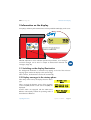
Information on the display
5 Information on the display
Sunny Boys and Sunny Mini Centrals have a factory-installed LCD display on the cover.
Detailed explanations of the individual operational parameters, error messages
and fault messages can be found in chapter 8 "Measurement channels and
messages" (Page 49).
5.1 Switching on the display illumination
The background illumination is switched on by tapping on the lid of the enclosure.
Tapping again switches the display to the next message.
After 2 minutes, the illumination switches off automatically.
5.2 Display messages in the startup phase
After startup of the inverter, the display shows the device
type.
SunnyBoy xxx
WRxx
After 6 seconds, the firmware version of the operation
control unit (BFR) and the current control unit (SRR) are
displayed.
BFR Version x.xx
SRR Version x.xx
Inverters which are equipped with the SMA Power
Balancer subsequently indicate the operating mode of
the SMA Power Balancer.
Power Balancer
PhaseGuard
Operating Instructions
SB_SMC-11:FE3206
Page 35
SMA Technologie AG
Information on the display
5.3 Display messages during operation
The display shows the most important operational information of the inverter in a
continuous cycle. The following five diagrams serve to clarify the messages. Each
message is displayed for 5 seconds. Then the cycle begins again.
The energy generated today and the current operating
mode are displayed first.
E-today
Mode
Finally, the present feed-in performance and voltage of
the solar generator are displayed.
Pac
Vpv
3.86kWh
MPP
903W
230V
With Multi-String inverters, the input voltage of each of
the two or three input strings is displayed as illustrated to
the right.
UPVA UPVB
600V 575V
With Multi-String inverters, this is then followed by the
input power of the two or three input strings.
PA/W PB/W
1325 1275
This is then followed by the total energy produced so far
and the operational hours of the device.
E-total
h-total
724.4kWh
512h
5.3.1 Fault displays
If an operational fault develops, the display immediately switches to "Fault" and the
background illumination is switched on.
The cause of the fault is displayed for 5 seconds in the
second line of the display.
If a measured value is responsible for the fault condition,
then the value measured at the time of the fault is
displayed. If another measurement is possible, the
present value is displayed in the second line.
Disturbance
Vac-Bfr
at:
present:
261V
245V
After another 5 seconds, normal operational information is again displayed. If the fault
is still present, the fault display starts again from the beginning. An overview of the status
messages and error messages can be found in chapter 8 "Measurement channels and
messages" (Page 49) of this document.
"Error ROM" indicates that the inverter has recognized a
fault in the EEPROM firmware. Contact SMA to have the
fault corrected.
Page 36
SB_SMC-11:FE3206
Error
ROM
Operating Instructions
SMA Technologie AG
Information on the display
5.3.2 DC overvoltage
If an excessive DC input voltage is present at the Sunny
Boy / Sunny Mini Central, then this is indicated by rapid
blinking of the background illumination and a
corresponding message.
!PV-Overvoltage!
!DISCONNECT DC !
Immediately disconnect the PV generator from the Sunny Boy / Sunny
Mini Central. The presence of excessive input voltage can lead to
irreparable damage!
Before returning the device into operation, the open circuit voltage of the PV generator
must be checked by an electrician!
5.3.3 SMA Power Balancer
The display messages described in this chapter only occur in systems which are
operated using the Sunny Mini Central with the integrated SMA Power Balancer. If
outputs of over 5 kVA are to be fed in one phase, it is usually necessary to construct a
3-phase system from three identical inverters. This is imperative to avoid an unbalanced
load between phases L1 - L3.
In order to also prevent an unbalanced load in the event of a fault in one of the three
devices, the integrated SMA Power Balancer (depending on the configuration) ensures
that the other two devices either deactivate, or reduce their output to 5 kVA over a 10
minute average. Furthermore, the SMA Power Balancer can be operated in four
different modes, which are described on the next page.
All the Sunny Mini Centrals must be operated in the same mode!
Operating Instructions
SB_SMC-11:FE3206
Page 37
Information on the display
SMA Technologie AG
Power Guard
If an inverter in "PowerGuard" mode indicates a device fault or grid fault, and
disconnects from the grid, the other two inverters reduce their output to 5 kVA over a
10 minute average.
Depending on the output which the inverter feeds into the
E-today
7.32kWh
grid, it shows two different display messages. If the
Mode
MPP
inverter's output is under 5 kVA, the mode "MPP" is
displayed. If the power output exceeds 5 kVA over a 10 minute average, the inverter
reduces its output correspondingly, in order to prevent an unbalanced load. When this
occurs, the display message switches from the mode "MPP"
to the mode "Balanced", in which the output is reduced
E-today
3.86kWh
to 5 kVA over a 10 minute average. The display
Mode
Balanced
message changes, depending on the output which the
inverter can feed into the grid. Thus, for example, it can occur that the inverter operates
in one of the two modes for several minutes, before returning to the other mode.
Phase Guard
If an inverter in "PhaseGuard" mode indicates a grid
Disturbance
voltage fault and disconnects from the grid, the other two
PowerBalance
inverters indicate the "PowerBalance" fault, and also
disconnect from the grid. Both devices subsequently switch to "Balanced" status (see
also chapter 8.2 "Status messages" (Page 52)).
Fault Guard
If an inverter in "FaultGuard" mode indicates a grid
Disturbance
voltage fault and disconnects from the grid, the other two
PowerBalance
inverters indicate the "PowerBalance" fault, and also
disconnect from the grid. Both devices subsequently switch to "Balanced" status (see
also chapter 8.2 "Status messages" (Page 52)).
If an inverter in "FaultGuard" mode indicates a device fault and disconnects from the
grid, the other two inverters indicate the "PowerBalance" fault 5 minutes later, and also
disconnect from the grid. Both devices subsequently switch to "Balanced" status (see
also chapter 8.2 "Status messages" (Page 52)).
Off
In "Off" mode, the SMA Power Balancer is deactivated. Operations are thus not
influenced by the SMA Power Balancer. The operating mode of the SMA Power
Balancer is indicated during the startup phase (see chapter 5.2 "Display messages in
the startup phase" (Page 35)).
Page 38
SB_SMC-11:FE3206
Operating Instructions
SMA Technologie AG
Maintenance and care
6 Maintenance and care
To enable the Sunny Boy / Sunny Mini Central to be used outdoors in places that are
difficult to access, the inverters have been constructed for low maintenance. To
guarantee safe operation, it is usually adequate to check the device visually for
damage approximately every two months. It should also be checked as to whether the
green LED is illuminated.
The Sunny Boy SB 2800i is not designed for installation outdoors. It is only suitable
for indoor installation.
However, in the interests of maximum yield, the operator should check weekly if
possible, under various conditions of solar irradiation, if the inverter's displays indicate
plausible normal operation (see chapter 4.4 "Description of the operating modes"
(Page 23)). Naturally, this information can also be obtained by using one of the
communications options.
Cleaning the inverter is only necessary if the heat dissipation is limited by dirty handle
covers (fan gills), dirty fans, dirty heatsinks or a dirty space between the Sunny Boy /
Sunny Mini Central and the wall. The dirt should be carefully removed with an
appropriate soft brush or paintbrush. A detailed description of how to clean the fans
(e.g. of the Sunny Boy SB 3800 or the Sunny Mini Central SMC 6000A) can be found
in the installation manual of the respective device.
If the display or the status LEDs are so dirty that they can no longer be seen, then they
can be cleaned with a damp cloth. Solvents, abrasives or corrosive liquids must not be
used!
Operating Instructions
SB_SMC-11:FE3206
Page 39
Maintenance and care
SMA Technologie AG
Page 40
Operating Instructions
SB_SMC-11:FE3206
SMA Technologie AG
System monitoring
7 System monitoring
A PV system with inverters from the Sunny Family can be monitored in different ways.
SMA offers a range of products for this purpose, allowing you to install a tailor-made
monitoring system for your PV system. If you require detailed information, request the
Sunny Family catalog or visit www.SMA.de. In the following sections the currently
available communications options are schematically described.
7.1 Sunny Data
Sunny Data is a PC program for direct
monitoring of your system. The connection
of Sunny Boys or Sunny Mini Centrals to
the PC is described in the following
sections.
Operating Instructions
SB_SMC-11:FE3206
Page 41
SMA Technologie AG
System monitoring
7.1.1 Sunny Data via Powerline
Communication via the grid power line
(up to 50 SMA inverters)
Requirements: the inverters must be equipped with a Powerline Piggy-Back and the PC
must have an SWR-COM or SWR-COM-USB plug modem. The connection to a PC via
the SWR-COM or SWR-COM-USB is described in the documentation for the SWRCOM / SWR-COM-USB.
SWR-COM
plug modem
PC with
Sunny Data
SWR-COM-USB
plug modem
PC with
Sunny Data
max. 50
max. 50
Sunny Mini Centrals cannot communicate via Powerline.
7.1.2 Sunny Data over RS232
Communication via a cable
(one SMA inverter)
Requirements: the inverter must be equipped with an RS232 Piggy-Back, the connection
to the PC usually occurs directly via the COM1 or COM2 port of the PC. The installation
of the RS232 cable is described in the inverter's installation manual.
PC with
Sunny Data
RS232
max. 12 m
Page 42
SB_SMC-11:FE3206
Operating Instructions
SMA Technologie AG
System monitoring
7.1.3 Sunny Data over RS485
Communication via a cable
(up to 50 SMA inverters)
Requirements: all inverters must be equipped with an RS485 Piggy-Back, the connection
with the PC usually occurs via an RS485/RS232 interface converter connected to the
COM1 or COM2 port or via an RS485/USB interface converter connected to the USB
port. The installation of the RS485 cable is described in the Sunny Data installation
manual.
Interface
converter
(RS485/RS232)
i-7520
PC with
Sunny Data
max. 50
RS232
RS485
max. 1200 m
Interface
converter
(RS485/USB)
i-7561
PC with
Sunny Data
max. 50
USB
RS485
max. 1200 m
Operating Instructions
SB_SMC-11:FE3206
Page 43
SMA Technologie AG
System monitoring
7.2 Sunny Beam
Simple wireless system monitoring for up to 4 SMA inverters.
Requirements: the inverters must be equipped with a radio Piggy-Back and a Sunny
Beam must be present at an appropriate distance. The maximum distance of the Sunny
Beam from the system is 30 m within a building and 100m outdoors. The installation of
the radio Piggy-Back is described in the Sunny Beam user manual.
With the Sunny Beam, the inverter parameters cannot be altered.
Sunny Beam
max. 4
7.2.1 Sunny Data Control over Sunny Beam
Communication with a PC over Sunny Beam
(up to 4 Sunny Boys or Sunny Mini Centrals)
Requirements: all 4 inverters must be equipped with a radio Piggy-Back and be
accessible to Sunny Beam for system monitoring. The maximum distance of the Sunny
Beam from the system is 30 m within a building and 100 m outdoors. The Sunny Beam
is connected to the PC via a USB cable. The installation of the radio Piggy-Backs and
the connection to the PC is described in the Sunny Beam user manual.
PC with
Sunny Data
Control
Sunny Beam
max. 4
Page 44
SB_SMC-11:FE3206
USB
Operating Instructions
SMA Technologie AG
System monitoring
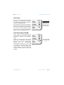
7.3 Sunny Boy Control Light
The simple data logger for PV systems with up to 10 inverters. The connection between
the Sunny Boy Control Light and the inverters occurs via Powerline.
Requirements: the inverters must be equipped with a Powerline Piggy-Back. The
installation is described in detail in the Sunny Boy Control Light documentation.
Sunny Boy
Control Light
max. 10
Powerline
Sunny Mini Centrals cannot communicate via Powerline.
7.4 Sunny Boy Control
The data logger for PV systems with up to 50 SMA inverters. The connection between
Sunny Boy Control and Sunny Boys / Sunny Mini Centrals can be made in the following
ways:
Powerline - communication via the grid power line
Requirements: all inverters must be equipped with a Powerline Piggy-Back. The
installation is described in detail in the Sunny Boy Control documentation.
Sunny Boy
Control
max. 50
Powerline
Sunny Mini Centrals cannot communicate via Powerline.
Operating Instructions
SB_SMC-11:FE3206
Page 45
SMA Technologie AG
System monitoring
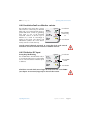
RS485 communication via a cable
Requirements: all inverters must be equipped with an RS485 Piggy-Back, the Sunny Boy
Control must be equipped with an RS485 Piggy-Back at the "COM1 - Sunny Boy"
interface. The installation is described in detail in the Sunny Boy Control documentation.
Sunny Boy
Control
max. 50
RS485
max. 1200 m
7.5 Sunny Boy Control Plus
The data logger for PV systems with up to 50 inverters, an additional interface for
connection to a PC or large display and additional connection possibilities for digital
and analog inputs and outputs. Requirements: see chapter 7.4 "Sunny Boy Control"
(Page 45).
Page 46
SB_SMC-11:FE3206
Operating Instructions
SMA Technologie AG
System monitoring
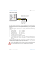
7.6 Sunny Data Control
This is a PC program for system monitoring and visualization on a PC for systems with
a Sunny Boy Control.
Requirements: PV system with Sunny Boy Control, Sunny Boy Control Plus, Sunny Boy
Control Light or Sunny Beam with a connection to a PC.
Connection also
possible via modem
Visualization
with Sunny
Data Control
Internet
display with
SDC agent
Internet
display with
Sunny Portal
Data analysis with
Excel
Remote desktop
The connection between the PC and the
Sunny Boy Control can occur via modem
if required. Large systems with more than
50 inverters can be monitored by
coupling several Sunny Boy Controls
together.
Operating Instructions
SB_SMC-11:FE3206
Page 47
SMA Technologie AG
System monitoring
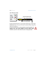
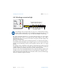
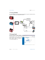
7.7 Sunny WebBox
The Sunny WebBox is a versatile inexpensive platform for system visualization directly
on a PC or via the Internet using the Sunny Portal.
Telephone
connection
Sunny
Portal
(Internet)
RS485
RS232
Powerline
Hub
Sunny
Matrix
LAN
LAN
LAN
PC
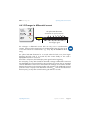
7.8 Sunny Portal
The Sunny Portal is a high performance
interface from SMA for the monitoring
and presentation of your system in the
Internet. Details can be obtained from the
Sunny Family catalog or directly at
www.SUNNY-PORTAL.com.
Page 48
SB_SMC-11:FE3206
Operating Instructions
SMA Technologie AG
Measurement channels and messages
8 Measurement channels and messages
If your inverter is equipped with a communications component, then numerous
measurement channels and messages can be transmitted.
The following abbreviations apply:
BFR:
Operation control unit
SRR:
Current control unit
8.1 Measurment channels
Measurement
channel
Description
Balancer
Indicates the currently active operating mode of the Sunny Mini
Central, which is set via the operating parameter "PowerBalancer".
dI
Leakage current of the PV system (inverter and PV generator)
E-Total
Total amount of feed-in energy
E-Total DC-A
Total amount of feed-in energy from string A
(Multi-String inverters only)
E-Total DC-B
Total amount of feed-in energy from string B
(Multi-String inverters only)
E-Total DC-C
Total amount of feed-in energy from string C
(Multi-String inverters only)
Event-Cnt
The number of events recorded since the last reset
Fac
Grid frequency
Fehler
Identification of the present fault / error.
Error
Fehler-Cnt
The number of faults recorded since the last reset
Error-Cnt
h-On
Total hours of operation
h-Total
Total hours of grid feed-in operation
h-Total DC-A
Total feed-in operational hours of string A
(Multi-String inverters only)
h-Total DC-B
Total feed-in operational hours of string B
(Multi-String inverters only)
h-Total DC-C
Total feed-in operational hours of string C
(Multi-String inverters only)
Operating Instructions
SB_SMC-11:FE3206
Page 49
Measurement channels and messages
Measurement
channel
Description
Iac-Ist
Grid current
Ipv
DC current
Netz-Ein
Total number of grid switch-ons
SMA Technologie AG
Power on
Pac
Instantaneous AC power
Phase
The phase to which the inverter is connected. The phase (L1 - L3) is
set via the operating parameter "Netzanschluss".
PPV DC-A
PV generator output string A (Multi-String inverters only)
PPV DC-B
PV generator output string B (Multi-String inverters only)
PPV DC-C
PV generator output string C (Multi-String inverters only)
Riso
Insulation resistance of the PV system to the grid connection
Erdschluss
Earthfault
Seriennummer
Inverter's serial number
Serial number
Status
Display of the current operating mode
State
Uac
Grid voltage
Vac
Ufan,
U-Fan
Fan supply voltage (only in inverters with an active cooling system)
Upv-Ist
PV input voltage
Vpv
Upv-Ist DC-A
PV input voltage string A (Multi-String inverters only)
Vpv DC-A
Upv-Ist DC-B
PV input voltage string B (Multi-String inverters only)
Vpv DC-B
Upv-Ist DC-C
PV input voltage string C (Multi-String inverters only)
Vpv DC-C
Page 50
SB_SMC-11:FE3206
Operating Instructions
SMA Technologie AG
Measurement channels and messages
Measurement
channel
Description
Upv-Soll
PV voltage
Vpv-Setpoint
Upv-Soll DC-A
PV voltage string A (Multi-String inverters only)
Upv-Soll DC-B
PV voltage string B (Multi-String inverters only)
Upv-Soll DC-C
PV voltage string C (Multi-String inverters only)
Zac
Grid impedance
Operating Instructions
SB_SMC-11:FE3206
Page 51
Measurement channels and messages
SMA Technologie AG
8.2 Status messages
Sunny Boys and Sunny Mini Centrals produce a range of status messages, depending
on the mode in which they are currently operating. The status messages can vary,
depending on the type of communication which you use.
Message
Description
Balanced
The Sunny Mini Central has disconnected itself from the grid, or is
limiting its output to 5 kVA over a 10 minute average. The Sunny
Mini Central is part of a three-phase system with two further Sunny
Mini Centrals and equipped with the SMA Power Balancer for
prevention of unbalanced loads. The "Balanced" message is
displayed as a result of the following:
Case 1:
The operating parameter "PowerBalancer" is set to "PhaseGuard".
One of the three Sunny Mini Centrals in this system has indicated a
grid fault, and disconnected itself from the grid. Thus, this Sunny
Mini Central also disconnects itself from the grid in order to prevent
an unbalanced load.
Case 2:
The operating parameter "PowerBalancer" is set to "PowerGuard".
One of the three Sunny Mini Centrals in this system has detected a
device fault or grid fault, and disconnected itself from the grid. The
two remaining Sunny Mini Centrals reduce their output to 5 kVA
over a 10 minute average, in order to prevent an unbalanced load.
Case 3:
The operating parameter "PowerBalancer" is set to "FaultGuard".
One of the three Sunny Mini Centrals in this system has indicated a
device fault or grid fault, and disconnected itself from the grid. In the
event of a grid fault, this Sunny Mini Central also immediately
disconnects itself from the grid in order to prevent an unbalanced
load. In the event of a device fault, the fault message is sent to the
other two devices with a delay of 5 minutes. After the 5 minutes have
passed, the other two devices disconnect themselves from the grid.
With the aid of chapter 8.4 "Fault messages" (Page 61), check
which fault occurred in the first inverter, and proceed as
recommended in that chapter.
Page 52
SB_SMC-11:FE3206
Operating Instructions
SMA Technologie AG
Measurement channels and messages
Message
Description
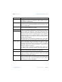
Derating
Overtemperature in the inverter. The Sunny Boy / Sunny Mini
Central reduces its performance to prevent the device from
overheating. To avoid unnecessary yield losses, the configuration
and string size should be checked. Check whether the Sunny Boy or
Sunny Mini Central can be located in a better position with better
ventilation, thus enabling sufficient heat dissipation. With fan
devices, check the fans for dirt.
A detailed description of how to clean the fans (e.g. of the Sunny
Boy SB 3800 or the Sunny Mini Central SMC 6000A) can be found
in the installation manual of the respective device.
Derating Idc,
derat. Idc,
Der. Idc
Derating WR,
Der. T. WR
Derating DC,
Der. T. DC
An overcurrent condition is present on the DC side of the inverter.
The inverter reduces the output power. This status does not damage
your system but energy is lost. If this message is regularly displayed,
ask your installation engineer to check your system.
Overtemperature in the inverter ("WR") or in the performance
electronics. The Sunny Boy / Sunny Mini Central reduces its output
to prevent the device from overheating. To avoid unnecessary yield
losses, the configuration and string size should be checked. Check
if the inverter can be installed in a better position with better
ventilation. With fan devices, check the fans for dirt.
A detailed description of how to clean the fans can be found in the
installation manual of the respective device.
Fehler,
Error
A fault has been detected (see chapter 8.4 "Fault messages" (Page
61)).
I-Konst
Constant current operation (the input current of the PV system is set
to a specified desired value, the inverter is not operating in MPP
mode). In some cases, this can be set as the operating mode.
I-Const
MPP
The Sunny Boy / Sunny Mini Central is operating in MPP mode. It
extracts the highest possible output from the PV generator. MPP is
the standard display when operating with normal sunshine.
Mpp Peak
The inverter is operating in MPP mode above its rated capacity.
Netzueb.
Testing the grid status, relay test etc.
grid. mon
This message appears during the startup phase, before the Sunny
Boy or Sunny Mini Central is connected to the grid. The message
usually appears in the morning and evening when there is little solar
irradiation. Grid monitoring is also performed after the occurrence
of a fault.
grid monitoring
Operating Instructions
SB_SMC-11:FE3206
Page 53
Measurement channels and messages
SMA Technologie AG
Message
Description
Off Grid
The inverter is in "Island" mode. This mode is specially conceived for
operation in a stand-alone grid with a Sunny Island as network
controller. More information about this topic can be obtained from
the Sunny Island operating manual under the category "Droop
Mode".
Offset
Offset compensation of the measurement electronics.
Riso
Measurement of the insulation resistance of the PV system.
Störung
Fault (see "Fault messages" table)
Stoer.
This fault occurs for reasons of safety and prevents the Sunny Boy /
Sunny Mini Central from connecting to the grid.
disturb.
disturbance
Stop
Interruption of operation after a fault. This status can also be set
manually.
Turbine Mode
The inverter is in "Turbine" mode. This mode is specially conceived
for use with wind energy systems. Further information on this topic
can be found in the Windy Boy instruction manuals
U-Konst,
Constant voltage operation (the input voltage of the PV system is set
to a specified desired value, the inverter is not operating in MPP
mode). In some cases, this can be set as the operating mode.
V-Const
Warten,
waiting
Page 54
The switch-on conditions are not (yet) satisfied.
SB_SMC-11:FE3206
Operating Instructions
SMA Technologie AG
Measurement channels and messages
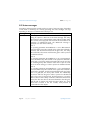
8.3 Operating parameters
Unauthorized changes to the operating parameters may result in:
•
injury or accidents as a result of changing the internal safety routines
in the Sunny Boy / Sunny Mini Central,
•
voiding the operating approval certificate of the Sunny Boy / Sunny
Mini Central,
•
voiding the guarantee of the Sunny Boy / Sunny Mini Central.
Never change the parameters of your Sunny Boy / Sunny Mini Central
without express authorization and instructions.
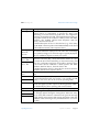
Name
Description
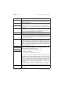
ACVtgRPro
Surge voltage protection (only relevant for Germany).
Sunny Boys and Sunny Mini Centrals can feed into the public grid
with up to 260 V AC. However, DIN VDE 0126-1-1 stipulates that
the average AC voltage over 10 minutes must not exceed 253 V. If
the average over 10 minutes exceeds the threshold value of 253 V,
the inverter disconnects itself from the grid. Once the average over
10 minutes returns to a value of less than 253 V, the inverter returns
to "Working" mode. If surge voltage protection is not required in the
relevant grid area (outside Germany), it can be deactivated by
means of presetting the LDVtgC parameter. In this event, only the
fast cut-off via the Uac-Max parameter intervenes.
AntiIsland-Ampl
Amplification of the AntiIsland process (alternative AntiIslanding
process, which is deactivated for Germany).
AntiIsland-Freq
Repetition rate of the AntiIsland process (alternative AntiIslanding
process, which is deactivated for Germany).
Betriebsart
Operating mode of the Sunny Boy / Sunny Mini Central:
Operating
Mode
MPP: Maximum Power Point
UKonst (V-Const): constant voltage mode (desired voltage is defined
in "Usoll-Konst" ("Vconst-Setpoint")).
IKonst (I-Const): operating mode for test purposes.
Stop: disconnection from grid, no operation.
Turbine Mode: operating mode for wind energy systems.
Off Grid: operating mode for inverters in a stand-alone grid.
Operating Instructions
SB_SMC-11:FE3206
Page 55
Measurement channels and messages
SMA Technologie AG
Name
Description
Control
Current regulation switching. If the operating parameter "Control" is
set to "Auto", the inverter automatically chooses the optimal type of
current regulation. If the operating parameter "Control" is set to
"Grid", the inverter regulates on the grid side. If set to "Bridge", the
inverter regulates on the bridge side. This setting can be a corrective
measure in the event of difficult grid characteristics. Discuss the
alteration of this parameter with the SMA hotline.
Default
Used for setting the country specific-information.
GER/ENS: country-specific parameter settings for Germany in
accordance with DIN VDE 0126 (4.99).
GER/VDE0126-1-1: country-specific parameter
Germany in accordance with DIN VDE 0126-1-1.
settings
for
SP/RD1663: country-specific parameter settings for Spain.
AUS/AS4777: country-specific parameter settings for Australia.
IT/DK5950: country-specific parameter settings for Italy.
GB/G83: country-specific parameter settings for Great Britain.
Other: here, parameter settings can be defined for countries for
which no predefined setting exists.
Trimmed: if country-specific parameters have been changed,
"trimmed" is shown in the display.
Off_Grid: setting for inverters which are operated in a stand-alone
grid. More detailed information can be found in the Sunny Island
manual.
dFac-Max
Maximum "grid frequency change" before the grid monitoring
system disconnects the device from the grid.
dZac-Max
Maximum "grid impedance change" before the grid monitoring
system disconnects the device from the grid.
Fac-delta-
Maximum frequency, above (Fac-delta+) and below (Fac-delta-) the
grid frequency of 50 or 60 Hz, before the grid monitoring system
disconnects the device from the grid.
Fac-delta+
Fac-LimitDelta
Fac-StartDelta
Fan-Test
Page 56
For setting the frequency-dependent output derating in the operating
mode "Off Grid". Further information on this topic can be found in
the Sunny Island instruction manual.
If you set the "Fan-Test" parameter to "1" you can check whether the
fan is functioning (only for fan devices).
SB_SMC-11:FE3206
Operating Instructions
SMA Technologie AG
Measurement channels and messages
Name
Description
LDVtgC
Compensation for the voltage drop in the cabling.
With this parameter, the voltage drop between the inverter and the
grid connection point is taken into account. The average voltage
over 10 minutes at the inverter connection must not exceed the sum
of ACVtgRPro plus LDVtgC. The parameter LDVtgC is preset to 0 V
for Germany. In grid areas in which the additional surge voltage
protection (see parameter ACVtgRPro) is not required, the
parameter LDVtgC is preset to 50 V. Thus, the surge voltage
protection is deactivated for these grid areas (253 V + 50 V =
303 V) and only the fast cut-off via the Uac-Max parameter
intervenes.
I-Ni-Test
Setting the impulse for impedance monitoring (0 = off).
testcurrent Zac
This parameter only functions when the inverter is deactivated
(disconnection on the AC side) or in "Stop" mode.
Inst.-Code
Parameters for self contained power system recognition can only be
changed after entering the "SMA grid guard" password.
KI-Wind-Reg
Control factors in Turbine Mode. Further information on this topic
can be found in the Windy Boy instruction manuals
KP-Wind-Reg
Netzanschluss
With this operating parameter, it is possible to store information in
the inverter, regarding which phase the inverter is connected to. This
means that in the system overview it is easy to manage which
inverter is installed at which phase.
NiTest
Activation and deactivation of the self contained power system
recognition by impedance monitoring (0 = off / 1 = on).
This parameter only functions when the inverter is deactivated
(disconnection on the AC side) or in "Stop" mode.
Operating Instructions
SB_SMC-11:FE3206
Page 57
Measurement channels and messages
SMA Technologie AG
Name
Description
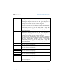
PowerBalancer
Operating mode of the SMA Power Balancer for prevention of
unbalanced loads in 3-phase systems with Sunny Mini Centrals. The
SMA Power Balancer has four operating modes:
Off: the SMA Power Balancer is deactivated. In the event of a
device fault or grid voltage fault at an inverter, only this inverter is
disconnected from the grid and the other two devices continue to run
at an undiminished power level.
PowerGuard: operating mode in which there is no distinction made
between a device fault and a grid voltage fault. The relevant device
disconnects itself from the grid, while the other two inverters limit
their output to 5 kVA over a 10 minute average.
PhaseGuard: operating mode in which a distinction is made
between a device fault and a grid voltage fault. In the event of a
device fault at the first Sunny Mini Central, the other two inverters
continue to operate without reducing their output. In the event of a
grid voltage fault, all devices immediately disconnect from the grid.
FaultGuard: operating mode in which a distinction is made between
a device fault and a grid voltage fault. In the event of a device fault,
the fault message is sent to the other two devices with a delay of
5 minutes. After the 5 minutes have passed, the other two devices
disconnect themselves from the grid. In the event of a grid voltage
fault, all devices immediately disconnect from the grid.
Pmax
Output limitation of the inverter.
P-Wind-Mid
Parameters for adjusting the inverter in Turbine Mode. Further
information on this topic can be found in the Windy Boy instruction
manuals
P-Wind-Ramp
Ripple-Ctl-Frq
Ripple-Ctl-Lev
Ripple-Ctl-Rcvr
The Ripple-Ctl-Frq, Ripple-Ctl-Lev, Ripple-Ctl-Rcvr parameters are
intended to handle ripple control signals from the SMA inverters.
These parameters are not available for all inverters. These
parameters may only be changed after prior agreement with SMA
Technologie AG.
Speicherfunktion Default Parameter: returns all parameter values to the factory
settings.
Memory function
Reset Betriebsdaten: returns all user-level parameter values to the
factory settings.
Reset Fehler: resets a permanent fault.
Page 58
SB_SMC-11:FE3206
Operating Instructions
SMA Technologie AG
Measurement channels and messages
Name
Description
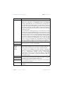
Storage
Permanent: modified parameters are stored in the EEPROM and can
be used even when the inverter has been restarted.
Store
Volatile: prevents the parameters from being stored in the EEPROM,
the parameters are only stored until the next restart.
T-Max-Fan
Temperature for the maximum fan speed.
T-Start
The period the inverter waits after the Upv-Start value has been
reached.
T-Start-Fan
The fan starts to run at minimum speed at this temperature.
T-Stop
The period the inverter waits before disconnecting from the grid
when Pac drops below the set value.
T-Stop-Fan
If after a temperature increase the inverter cools down to below this
threshold value, the fan switches itself off again.
Uac-Min
Lower (Uac-Min) and upper (Uac-Max) limits of the allowable AC
voltage (self contained power system recognition), before the grid
monitoring system disconnects the device from the grid.
Vac-Min
Uac-Max
Vac-Max
UdcWindMax
UdcWindMid
Parameters for adjusting the inverter in Turbine Mode. Further
information on this topic can be found in the Windy Boy instruction
manuals
UdcWindStart
Upv-Start
The DC voltage required before the inverter begins feeding power
into the grid.
Usoll-Konst
PV desired voltage for constant operational voltage. These
parameters are only important when the "Betriebsart" parameter is
set to U-konst (V-Const).
Zac-Max
Maximum "grid impedance" before the grid monitoring system
disconnects the device from the grid.
Operating Instructions
SB_SMC-11:FE3206
Page 59
Measurement channels and messages
SMA Technologie AG
8.3.1 Non-modifiable parameters
The following parameters are displayed in the parameter list but cannot be changed:
Name
Description
Fac-Pderating
Frequency-dependent output limitation
Fac-Tavg
Averaging time of grid frequency gaging
Hardware-BFS
Hardware version of the operation control unit (BFR)
Plimit
Upper limit for AC output power
SMA-SN
Inverter's serial number
Software-BFR
Firmware version of the operation control unit (BFR)
Software-SRR
Firmware version of the current control unit (SRR)
Uac-Tavg
Averaging time of grid frequency gaging
Page 60
SB_SMC-11:FE3206
Operating Instructions
SMA Technologie AG
Measurement channels and messages
8.4 Fault messages
If a fault develops, the Sunny Boys and Sunny Mini Centrals generate a message, the
nature of which depends on the operating mode and the type of fault.
Fault code
Description
!PVOvervoltage!
Overvoltage at DC input.
Immediately disconnect the inverter from the PV generators!
!Disconnect DC ! Otherwise, the inverter may be damaged.
Check the configuration of your system and measure the DC voltage
before reconnecting the inverter to the DC voltage.
ACVtgRPro
The average grid voltage over 10 minutes is no longer within the
permissible range.
This can be due to either of the following reasons:
•
The grid voltage at the connection point is too high.
•
The grid impedance at the connection point is too high.
The inverter disconnects to allow compliance with the voltage
quality of the grid. Check the grid voltage at the connection point of
the Sunny Boys and/or Sunny Mini Centrals. If, due to the local grid
conditions, the grid voltage increases to 253 V or more, ask the
electricity provider whether the voltage at the feed-in point can be
adjusted, or whether they agree to an alteration of the threshold
value ACVtgRPro (operating parameter: ACVtgRPro) for voltage
quality monitoring.
If the grid voltage is continuously within the acceptable range, yet
the "ACVtgRPro" fault is still displayed, contact the SMA hotline.
Bfr-Srr
Internal measurement comparison fault or hardware defect. Contact
SMA if this fault occurs frequently.
CAN
Internal communications fault. Contact SMA if this fault occurs
frequently.
DCBFS-Startup
Internal communications fault. Contact SMA if this fault occurs
frequently.
DC-A def.
A string input is faulty. Contact SMA if this fault is displayed.
DC-B def.
DC-C def.
DCBFS Version
DC-BFS has the wrong firmware version. Contact SMA if this fault is
displayed.
Delta Bfr-Srr
Internal measurement comparison fault or hardware defect. Contact
SMA if this fault occurs frequently.
Operating Instructions
SB_SMC-11:FE3206
Page 61
Measurement channels and messages
SMA Technologie AG
Fault code
Description
Derating
Once the inverter enters the "Derating" mode, it displays the
"Derating" warning until the device is completely switched off (in the
evening). Further information on this fault message can be found in
chapter 4.4.7 "Derating" (Page 26).
dFac-Bfr
The changes in grid frequency exceed the permissible range ("Bfr"
or "Srr" is an internal message that has no meaning for the user).
dFac-Srr
dI-Bfr
dI-Srr
For reasons of safety, the inverter disconnects itself from the grid. If
possible, check the grid frequency and check how often major
deviations occur. If repeated frequency variations occur and this is
causing "dFac-Bfr" or "dFac-Srr" faults, ask the electricity provider if
they agree to a modification of the operating parameters (dFacMax). Discuss the proposed parameters with the SMA hotline.
The inverter has detected a drastic change in the leakage current.
This fault only occurs in transformerless inverters that have no
galvanic isolation from the grid. The integrated leakage current
monitoring is an important component for providing personal safety.
The cause for a drastic change in the leakage current can be a
sudden grounding fault, fault current or an actual fault in the device.
The inverter disconnects itself from the grid. If the "dI-Bfr" or "dI-Srr"
fault messages occur without obvious reason, consult a qualified
electrician and ask them to check your system for correct insulation
and a possible ground fault.
dI-Mess
Deviation in the leakage current measurement / leakage current. If
this fault occurs repeatedly, the inverter indicates a permanent
restriction of operation. You can attempt to remove the fault with the
aid of a communication interface and the corresponding
communication product (e.g. PC with Sunny Data or Sunny Boy
Control). If this is unsuccessful, consult the Sunny Boy hotline to
discuss further action.
dI-Test
Fault in the leakage current measurement. Contact SMA if this fault
occurs frequently.
dZac-Bfr
The changes in grid impedance exceed the permissible range ("Bfr"
or "Srr" is an internal message that has no meaning for the user).
dZac-Srr
Page 62
For reasons of safety, the inverter disconnects itself from the grid. If
possible, check the grid impedance and check how often major
deviations occur. If repeated frequency variations occur and this is
causing "dZac-Bfr" or "dZac-Srr" faults, ask the electricity provider if
they agree to a modification of the operating parameters (dZacMax). Discuss the proposed parameter changes with the SMA
hotline.
SB_SMC-11:FE3206
Operating Instructions
SMA Technologie AG
Measurement channels and messages
Fault code
Description
EEPROM
A data transfer fault occurred during reading or writing of data from
the EEPROM, the data is not relevant for safe operation - this fault
has no effect on performance.
EEPROM dBh
Data EEPROM is defective, the device has switched itself off
because the loss of data has disabled important functions of the
inverter. Contact SMA.
EeRestore
One of the duplicate data sets in the EEPROM is defective and has
been reconstructed without loss of data.
Fac-Bfr
The grid frequency is no longer within the permissible range ("Bfr"
or "Srr" is an internal message that has no meaning for the user). For
reasons of safety, the Sunny Boy / Sunny Mini Central disconnects
itself from the grid. Check the grid frequency and the grid
connection on the inverter. If the grid frequency lies outside the
permissible range because of local conditions, ask the electricity
provider if they agree to a modification of the operating parameters
(Fac-delta- and Fac-delta+).
Fac-Srr
If the grid frequency lies within an acceptable range, yet "Fac-Bfr"
or "Fac-Srr" faults are still being displayed, contact the SMA hotline.
Iac-DC_Offs-Srr
The DC component of the electricity fed into the grid is no longer
within the permissible range. For reasons of safety, the inverter
disconnects itself from the grid. If the grid current is outside the
permissible range due to local grid conditions, contact the local
electricity provider for assistance.
If the grid current lies within the acceptable range, yet the "IacDC_Offs-Srr" fault is still being displayed, contact the SMA hotline.
IGBTs
The internal hardware monitoring has detected a fault in the power
electronics. Contact SMA if this fault occurs frequently.
Imax
Overcurrent on the AC side. This fault code is displayed if the current
in the AC network is larger than specified. Check your system
configuration and the grid conditions.
Imax DC
Overcurrent in the DC circuit of the Sunny Boy Multi-String. The
inverter is experiencing a current that lies above the specified value
for the DC circuit. This is caused by excessive current on the DC
input. Check your system configuration.
Operating Instructions
SB_SMC-11:FE3206
Page 63
Measurement channels and messages
SMA Technologie AG
Fault code
Description
K1-Schliess
Fault during relay test. Please contact SMA if this fault occurs often
or repeatedly.
K1-Close
K1-Trenn
K1-Open
Kom DC-BFS
Internal communications fault. Contact SMA if this fault occurs
frequently.
L<->N
L and N are swapped on the AC connection. Ask an installation
engineer to check the system.
L-Netz
A grid relay is faulty. The inverter checks the relays connecting it with
the grid before feeding power into the grid. If the relays are not
functioning correctly, the disconnection from the grid may not work
properly, so the inverter does not connect to the grid.
If this fault occurs repeatedly, the inverter indicates a permanent
restriction of operation. You can attempt to remove the fault with the
aid of a communication interface and the corresponding
communication product (e.g. PC with Sunny Data or Sunny Boy
Control). If this is unsuccessful, consult the Sunny Boy hotline to
discuss further action.
L-WR
A grid relay is faulty. The inverter checks the relays connecting it with
the grid before feeding power into the grid. If the relays are not
functioning correctly, the disconnection from the grid may not work
properly, so the inverter does not connect to the grid.
If this fault occurs repeatedly, the inverter indicates a permanent
restriction of operation. You can attempt to remove the fault with the
aid of a communication interface and the corresponding
communication product (e.g. PC with Sunny Data or Sunny Boy
Control). If this is unsuccessful, consult the Sunny Boy hotline to
discuss further action.
MWE Defekt DC Internal measurement comparison fault or hardware defect. Contact
SMA if this fault occurs frequently.
Meas DC
Page 64
SB_SMC-11:FE3206
Operating Instructions
SMA Technologie AG
Measurement channels and messages
Fault code
Description
N-Netz
A grid relay is faulty. The inverter checks the relays connecting it with
the grid before feeding power into the grid. If the relays are not
functioning correctly, the disconnection from the grid may not work
properly, so the inverter does not connect to the grid.
If this fault occurs repeatedly, the inverter indicates a permanent
restriction of operation. You can attempt to remove the fault with the
aid of a communication interface and the corresponding
communication product (e.g. PC with Sunny Data or Sunny Boy
Control). If this is unsuccessful, consult the Sunny Boy hotline to
discuss further action.
N-WR
A grid relay is faulty. The inverter checks the relays connecting it with
the grid before feeding power into the grid. If the relays are not
functioning correctly, the disconnection from the grid may not work
properly, so the inverter does not connect to the grid.
If this fault occurs repeatedly, the inverter indicates a permanent
restriction of operation. You can attempt to remove the fault with the
aid of a communication interface and the corresponding
communication product (e.g. PC with Sunny Data or Sunny Boy
Control). If this is unsuccessful, consult the Sunny Boy hotline to
discuss further action.
NUW-dI
Internal measurement comparison fault or hardware defect. Contact
SMA if this fault occurs frequently.
NUW-FAC
Internal measurement comparison fault or hardware defect. Contact
SMA if this fault occurs frequently.
MSD-Fac
NUW-UAC
MSD-Vac
NUW-Timeout
MSD-Timeout
NUW-ZAC
MSD-Zac
Offset
Operating Instructions
Internal measurement comparison fault or hardware defect. Contact
SMA if this fault occurs frequently.
Internal measurement comparison fault or hardware defect. Contact
SMA if this fault occurs frequently.
Internal measurement comparison fault or hardware defect. Contact
SMA if this fault occurs frequently.
Fault in the acquisition of measurement data. Contact SMA if this
fault occurs frequently.
SB_SMC-11:FE3206
Page 65
Measurement channels and messages
SMA Technologie AG
Fault code
Description
PowerBalance
The Sunny Mini Central is part of a three-phase system with two
further Sunny Mini Centrals and equipped with the SMA Power
Balancer for prevention of unbalanced loads. The operating
parameter "PowerBalancer" is set to "PhaseGuard" or "FaultGuard".
In the "PhaseGuard" operating mode, one of the three Sunny Mini
Centrals in this system has detected a grid fault, and disconnected
itself from the grid. The two other inverters receive a message and
for a short period display the "PowerBalance" fault, before switching
to "Balanced" status.
In the "FaultGuard" operating mode, one of the three Sunny Mini
Centrals in this system has detected either a device fault or a grid
fault, and disconnected itself from the grid. In the event of a device
fault, the two other inverters receive the fault message after a delay
of 5 minutes, then for a short period display the "PowerBalance"
fault, before switching to "Balanced" status. In the event of a grid
fault, the two other inverters immediately receive a fault message
and for a short period display the "PowerBalance" fault, before
switching to "Balanced" status (more information on the "Balanced"
status can be found in chapter 8.2 "Status messages" (Page 52)).
Rechner
MSD-Timeout
Relais
Relais
Relais
Relais
1
2
3
4
Riso
Erdschluss
Functional fault in one of the two microcontrollers. Please contact
SMA if this fault occurs often or repeatedly.
A grid relay is faulty. The inverter checks the relays connecting it with
the grid before feeding power into the grid. If the grid relays do not
function properly, the inverter cannot connect itself to the grid.
If this fault occurs repeatedly, the inverter indicates a permanent
restriction of operation. You can attempt to remove the fault with the
aid of a communication interface and the corresponding
communication product (e.g. PC with Sunny Data or Sunny Boy
Control). If this is unsuccessful, consult the Sunny Boy hotline to
discuss further action.
The electrical insulation between the PV system and ground is faulty.
The resistance between the DC plus and/or DC minus connection
and the ground is outside the defined limit range.
Earthfault
Have a qualified electrician check your system for correct insulation
and a possible ground fault.
ROM
The inverter's firmware is faulty. Contact SMA if this fault occurs
frequently.
Page 66
SB_SMC-11:FE3206
Operating Instructions
SMA Technologie AG
Measurement channels and messages
Fault code
Description
SD-DI-Wandler
The inverter has detected an insulation fault on the DC side. Have a
qualified electrician check your system for correct insulation and a
possible ground fault.
SD-Imax
The inverter has detected an overcurrent on the AC side. It
disconnects itself from the grid for safety reasons, then attempts to
reconnect itself to the grid. Contact SMA if this fault occurs
frequently.
Overcurrent
SD-WR-Bruecke
The inverter has detected a fault in the power electronics. It
disconnects itself from the grid, then attempts to reconnect itself to
the grid. Contact SMA if this fault occurs frequently.
Shutdown
Temporary inverter fault.
Trafo-Temp-F
The transformer has reached an unacceptably high temperature.
The inverter stops feeding the grid until the temperature lies within
the acceptable range. If this fault occurs frequently, check the heat
dissipation of the device.
Trafo-Temp-W
If the transformer reaches an unacceptably high temperature, the
inverter stops feeding the grid until the transformer has reached an
acceptable temperature and the system can begin feeding the grid
again. The Trafo-Temp-W warning is displayed until the next time the
device is completely switched off (at the end of the day). Check the
heat dissipation of the inverter.
Uac-Bfr
The grid current is no longer within the permissible range ("Bfr" or
"Srr" is an internal message that has no meaning for the user). The
Uac fault can have the following causes:
Vac-Bfr
Uac-Srr
•
Grid disconnected (circuit breaker or fuse)
Vac-Srr
•
Broken AC cable or
•
AC cable has a high internal resistance
For reasons of safety, the inverter disconnects itself from the grid.
Check the grid current and the grid connection on the inverter. If the
grid voltage lies outside the acceptable range because of local grid
conditions, ask the electricity provider if the voltage can be adjusted
at the feed-in point or if they agree to changes in the values of the
monitored operational limits (operating parameters: Uac-Min and
Uac-Max).
If the grid voltage lies within an acceptable range, yet "Uac-Bfr" or
"Uac-Srr" faults are still being displayed, contact the SMA hotline.
UDiff
Operating Instructions
Fault in intermediate circuit. Contact SMA if this fault occurs
frequently.
SB_SMC-11:FE3206
Page 67
Measurement channels and messages
Fault code
Description
Upv-Max
Overvoltage at DC input.
SMA Technologie AG
Immediately disconnect the inverter from the PV generators!
Otherwise, the inverter may be damaged.
Check the configuration of your system and measure the DC voltage
before reconnecting the inverter to the DC voltage.
Uzkposneg<10
Fault in auxilliary circuit. Contact SMA if this fault occurs frequently.
UZWK-Max
The internal hardware monitor has detected an overvoltage
condition in the intermediate circuit of the inverter. Contact SMA if
this fault occurs frequently.
Watchdog
Fault in the program code flow monitoring
Watchdog-Srr
Zac-Bfr
Zac-Srr
The grid impedance is no longer within the permissible range ("Bfr"
or "Srr" is an internal message that has no meaning for the user). For
reasons of safety, the inverter disconnects itself from the grid. The
impedance is calculated from the grid impedance and the
impedance of the grid connection cable (AC cable) of the inverter.
Check the grid impedance and grid connection on the inverter. Use
a grid connection cable with an adequate cross section (= low
impedance), observe the advice to this effect in the installation
manual. This fault may also be rectified by tightening the AC fuse. If
the fault continues to occur, contact SMA to discuss further action.
Page 68
SB_SMC-11:FE3206
Operating Instructions
SMA Technologie AG
Measurement channels and messages
8.5 Declaration of conformity (CE)
CE Declaration of Conformity
for utility interactive inverters
Product:
Type:
Sunny Boy
SB 700, SB 1100, SB 1100LV, SB 1700, SB 2100TL,
SB 2500, SB 2800i, SB 3000, SB 3300TL, SB 3300TL HC
We declare that the above specified devices are compliant with the regulations of the European
Community, in terms of the design and the version fabricated by SMA. This especially applies
for the EMC Regulation defined in 89/336/EWG and the LV- regulation defined in
73/23/EWG.
The devices are compliant with the following standards:
EMC:
Emission:
Utility Interference:
Immunity:
Safety:
Semiconductor-Converter:
DIN
DIN
DIN
DIN
DIN
DIN
DIN
DIN
DIN
EN 61000-6-3: 2002-08
EN 61000-6-4: 2002-08
EN 55022: 2003-09, Class B
EN 61000-3-3: 2002-05
EN 61000-3-2: 2001-12
EN 61000-6-1: 2002-08
EN 61000-6-2: 2002-08
EN 50178: 1998-04
EN 60146-1-1: 1994-03
The above mentioned devices are therefore marked with a CE sign.
Note:
This declaration of conformity becomes invalid in case without explicit written confirmation by SMA, when
·
the product is modified, complemented or changed,
·
and/or components, other than those belonging to the SMA accessories, are installed in the product,
·
as well as in case of incorrect connection or inproper usage
.
Niestetal, 13.03.2006
SB-K16A-CE-12:BE1706
SMA Technologie AG
i.V. Frank Greizer
(Head of Development Department Solar Technology)
SMA Technologie AG
Hannoversche Strasse 1-5
34266 Niestetal
Tel. +49 561 9522 – 0
Fax +49 561 9522 – 100
www.SMA.de
[email protected]
Operating Instructions
SB_SMC-11:FE3206
Page 69
SMA Technologie AG
Measurement channels and messages
CE Declaration of Conformity
for utility interactive inverters
Product:
Type:
Sunny Boy
SB 3300, SB 3800, SB 4200TL Multi-String,
SB 4200TL HC Multi-String, SB 5000TL Multi-String,
SB 5000TL HC Multi-String
We declare that the above specified devices are compliant with the regulations of the
European Community, in terms of the design and the version fabricated by SMA. This especially applies for the EMC Regulation defined in 89/336/EWG and the low voltage regulation
defined in 73/23/EWG.
The devices are compliant with the following standards:
EMC:
Emission:
Utility Interference:
Immunity:
Safety:
Semiconductor-Converter:
DIN
DIN
DIN
DIN
DIN
DIN
DIN
DIN
DIN
EN 61000-6-3: 2002-08
EN 61000-6-4: 2002-08
EN 55022: 2003-09, Class B
EN 61000-3-11: 2001-04
EN 61000-3-12: 2004-06 (Draft)
EN 61000-6-1: 2002-08
EN 61000-6-2: 2002-08
EN 50178: 1998-04
EN 60146-1-1: 1994-03
The above mentioned devices are therefore marked with a CE sign.
Note:
This declaration of conformity becomes invalid in case without explicit written confirmation by SMA
·
the product is modified, complemented or changed,
·
and/or components, other than those belonging to the SMA accessories, are installed in the product,
·
as well as in case of incorrect connection or inproper usage
i.V. Frank Greizer
(Head of Development Department Solar Technology)
SB-G16A-CE-12:BE1706
Niestetal, 13.03.2006
SMA Technologie AG
SMA Technologie AG
Hannoversche Strasse 1-5
34266 Niestetal
Tel. +49 561 9522–0
Fax +49 561 9522–100
www.SMA.de
[email protected]
Page 70
SB_SMC-11:FE3206
Operating Instructions
SMA Technologie AG
Measurement channels and messages
CE Declaration of Conformity
for utility interactive inverters
Product:
Type:
Sunny Mini Central
SMC 5000, SMC 5000A, SMC 6000, SMC 6000A,
SMC 6000TL, SMC 7000TL, SMC 8000TL
We declare that the above specified devices are compliant with the regulations of the European
Community, in terms of the design and the version fabricated by SMA. This especially applies
for the EMC Regulation defined in 89/336/EWG and the low voltage regulation defined in
73/23/EWG.
The devices are compliant with the following standards:
EMC:
Emission:
Utility Interference:
Immunity:
Safety:
Semiconductor-Converter:
DIN
DIN
DIN
DIN
DIN
DIN
DIN
DIN
DIN
EN 61000-6-3: 2002-08
EN 61000-6-4: 2002-08
EN 55022: 2003-09, Class B
EN 61000-3-11:2001-04
EN 61000-3-12: 2004-06 (Draft)
EN 61000-6-1: 2002-08
EN 61000-6-2: 2002-08
EN 50178: 1998-04
EN 60146-1-1: 1994-03
The above mentioned devices are therefore marked with a CE sign.
Note:
This declaration of conformity becomes invalid in case
·
the product is modified, complemented or changed,
·
and/or components, other than those belonging to the SMA accessories, are installed in the product,
·
as well as in case of incorrect connection or inproper usage
without explicit written confirmation by SMA.
Niestetal, 13.03.2006
SMC-CE-12:BE1106
SMA Technologie AG
i.V. Frank Greizer
(Head of Development Department Solar Technology)
SMA Technologie AG
Hannoversche Straße 1-5
34266 Niestetal
Tel. +49 561 9522 – 0
Fax +49 561 9522 – 100
www.SMA.de
[email protected]
Operating Instructions
SB_SMC-11:FE3206
Page 71
Measurement channels and messages
SMA Technologie AG
8.6 Clean report of findings
Sunny Boys and Sunny Mini Centrals are equipped with the independent disconnection
device "SMA grid guard" and are covered by the industrial trade association "SMA
grid guard" certificate.
DIN VDE 0126 (04.99)
Page 72
SB_SMC-11:FE3206
Operating Instructions
SMA Technologie AG
Measurement channels and messages
DIN VDE 0126-1-1
In chapter 1.3 "Identification of the inverter" (Page 9), it is explained which SMA
grid guard certificate applies to your inverter.
Operating Instructions
SB_SMC-11:FE3206
Page 73
Measurement channels and messages
SMA Technologie AG
Page 74
Operating Instructions
SB_SMC-11:FE3206
SMA Technologie AG
Glossary
9 Glossary
AC
Abbreviation for "Alternating Current"
Central inverter
An inverter concept, in which all PV modules are connected to each other (in series
and/or parallel) and which uses a single inverter for feeding energy into the external
grid.
DC
Abbreviation for "Direct Current"
Derating
A controlled reduction in performance, usually dependent on component temperatures.
Compared with the normal process of completely shutting down the device, the effect
on the external power network is smaller with derating.
Grid-coupled system
A PV system that is connected to the supply grid of an external energy supplier.
Grid impedance
The grid impedance is a characteristic grid specification, which is determined by the
grid's infrastructure, as well as by the number of power suppliers and power consumers.
If supply to the grid section drops out due to a grid shutdown on the part of the adjacent
supplier (medium voltage transformer), the grid impedance changes abruptly. In order
to detect this occurrence, and to prevent an unwanted stand-alone grid, SMA grid
guard measures the grid impedance and disconnects the inverter from the grid in the
event of a jump in impedance.
Inverter
A device for converting the direct current (DC) from the PV generator into alternating
current (AC), which is used by most normal household devices and especially for
feeding energy into an existing supply grid. Inverters for PV systems usually contain one
or more MPP trackers.
Maximum Power Point "MPP"
The operational point (current / voltage) of the PV generator at which the highest
possible performance under the prevailing conditions is achieved. The actual MPP
changes constantly depending (e.g.) on the level of solar irradiation and the cell
temperature.
MPP tracker
A device that adjusts the voltage and current of a PV generator so that it is operated at
its "Maximum Power Point". The "Maximum Power Point" is the operating point with the
maximum power output.
Operating Instructions
SB_SMC-11:FE3206
Page 75
SMA Technologie AG
Glossary
Multi-String inverter
An inverter that combines the advantages of several string inverters (separate MPP
trackers for the individual strings) and a central inverter (lower performance-specific
costs).
NLM
Abbreviation for "Netzleitungsmodem" (Powerline modem). The communication
between SMA inverters and the monitoring devices can be made with a cable or
wireless link, but also via grid communication. In the NLM system, a carrier frequency
of approx. 132 kHz is modulated onto the AC cables, and the data is then transferred
using FSK ("Frequency Shift Keying") of this carrier signal. Details on the NLM can be
found (e.g.) in the technical description of the SWR-COM.
PLC
Abbreviation for "Powerline Communication", describes the process of data transfer
over the grid supply cables. The PLC power module is used to amplify the signal and is
installed in Multi-String inverters and Sunny Mini Centrals SMC 5000 and SMC 6000.
PV
Abbreviation for "Photovoltaic", describes the conversion of solar energy into electrical
energy.
PV generator
Technical device for the conversion of light energy into electrical energy. This normally
also describes all installed and electrically connected solar modules in a PV system.
PV module
A collection of individual solar cells in an enclosure that protects the sensitive cells from
mechanical stresses and allows easy installation.
PV system
Describes the complete collection of components needed for the acquisition and
utilization of solar energy. As well as the PV generator, this also includes the Sunny Boy
or Sunny Mini Central, for example, in the case of grid-coupled systems.
SMA grid guard
Part of an "independent disconnection device for electrical power units". This is a
mandatory safety device that prevents power from a solar energy system being fed into
a deactivated grid when the external power generators are not functioning. In the
Sunny Boy / Sunny Mini Central, this function is assumed by the "SMA grid guard".
Page 76
SB_SMC-11:FE3206
Operating Instructions
SMA Technologie AG
Glossary
SMA Power Balancer
The SMA Power Balancer refers to a circuit connection of three Sunny Mini Centrals to
a 3-phase low-voltage grid. This circuit connection is used to prevent unbalanced loads
between two phases as specified by the "electrical power units on the low-voltage grid"
VDEW guideline.
The installation engineer can use the "PowerBalancer" parameter to stipulate whether,
in the event of an inverter fault, an unbalanced load is to be avoided by deactivation
of the other two inverters, or by limiting their power to an average of 5 kVA over 10
minutes.
Solar cell
An electronic component that generates electrical energy when irradiated with sunlight.
Since the voltage produced by a solar cell is very small (approx. 0.5 V), several solar
cells are combined to form a solar module. The most common material presently used
for solar cells is silicon, which is manufactured in different forms (monocrystalline,
polycrystalline, amorphous). In addition to different mechanical variations, that are
usually designed to increase the level of efficiency, completely new materials are
currently being tested (cadmium telluride, cadmium indium sulphide, titanium dioxide
and many others.)
Solar energy
"Sun energy", i.e. energy from sunlight (solar radiation).
Solar module
A collection of individual solar cells in an enclosure that protects the sensitive cells from
mechanical stresses and allows easy installation.
Stand-alone grid system
An energy generation system that is completely independent of any external grid.
String
Describes a group of solar modules electrically connected in series.
String inverter
An inverter concept that avoids the disadvantages of the central inverter concept. The
PV generator is split into individual strings, each of which feeds the grid by means of its
own string inverter. This greatly simplifies installation, and the yield losses caused by
manufacturing deviations or variations in shadowing of the solar modules are greatly
reduced.
Unbalanced load
The difference between the power fed into the grid at the individual phase conductors.
In Germany, this is not permitted to exceed a rated output of 4.6 kVA (plus 10 %
overload, so in total 5 kVA).
Operating Instructions
SB_SMC-11:FE3206
Page 77
SMA Technologie AG
Glossary
Varistor
In the Sunny Boy and Sunny Mini Central, the varistors serve to guard against
atmospheric overvoltages, e.g. nearby lightning strikes. They divert overvoltages in
order to protect the electronics in the Sunny Boy or Sunny Mini Central. During
operation, varistors are subject to a certain degree of ageing. Varistors which have
already been operating for a considerable period of time, or have already needed to
divert overvoltages, become highly resistive. Thermally monitored varistors detect
increased temperature (which suggests such "ageing"). If one of the varistors is no
longer functional, the inverter triggers a fault message.
Page 78
SB_SMC-11:FE3206
Operating Instructions
SMA Technologie AG
Contact
10 Contact
If you have any questions or technical problems concerning your inverter, please
contact our service hotline. Have the following information available when you contact
SMA:
•
Inverter type
•
Communication method
•
Type and number of modules connected
•
Inverter's serial number
•
Inverter's blink code or display
Address:
SMA Technologie AG
Hannoversche Strasse 1 - 5
34266 Niestetal
Germany
Tel.: +49 (561) 95 22 - 499
Fax: +49 (561) 95 22 - 4699
[email protected]
www.SMA.de
Operating Instructions
SB_SMC-11:FE3206
Page 79
SMA Technologie AG
Contact
Page 80
SB_SMC-11:FE3206
Operating Instructions
Legal Restrictions
SMA Technologie AG
The information contained in this document is the property of SMA Technologie AG. Publishing its content,
either partially or in full, requires the written permision of SMA Technologie AG. Any internal company copying
of the document for the purposes of evaluating the product or its correct implementation is allowed and does
not require permission.
Exclusion of liability
The general terms and conditions of delivery of SMA Technologie AG shall apply.
The content of these documents is continually checked and amended, where necessary. However,
discrepancies cannot be excluded. No guarantee is made for the completeness of these documents. The latest
version is available on the Internet at www.SMA.de or from the usual sales channels.
Guarantee or liability claims for damages of any kind are exlcuded if they are caused by one or more of the
following:
• Improper or inappropriate use of the product
• Operating the product in an unintended environment
• Operating the product whilst ignoring relevant, statutory safety regulations in the deployment location
• Ignoring safety warnings and instructions contained in all documents relevant to the product
• Operating the product under incorrect safety or protection conditions
• Altering the product or supplied software without authority
• The product malfunctions due to operating attached or neighboring devices beyond statutory limit values
• In case of unforeseen calamity or force majeure
Software licensing
The use of supplied software produced by SMA Technologie AG is subject to the following conditions:
This software may be copied for internal company purposes and may be installed on any number of
computers. Supplied source codes may be changed or adapted for internal company purposes on your own
responsibility. Drivers may also be transferred to other operating systems. Source codes may only be published
with the written permission of SMA Technologie AG. Sub-licensing of software is not permissible.
Limitation of liability: SMA Technologie AG rejects any liability for direct or indirect damages arising from the
use of software developed by SMA Technologie AG. This also applies to the provision or non-provision of
support activities.
Supplied software not developed by SMA Technologie AG is subject to the respective licensing and liability
agreements of the manufacturer.
Trademarks
All trademarks are recognized even if these are not marked separately. Missing designations do not mean that
a product or brand is not a registered trademark.
SMA Technologie AG
Hannoversche Straße 1-5
34266 Niestetal
Germany
Tel. +49 561 9522-0
Fax +49 561 9522-100
www.SMA.de
E-mail: [email protected]
© 2005 SMA Technologie AG. All rights reserved.
Page 81
SB_SMC-11:FE3206
Operating Instructions
Sales
Solar Technology
www.SMA.de
SMA Technologie AG
Hannoversche Strasse 1–5
34266 Niestetal, Germany
Tel. : +49 561 9522 4000
Fax: +49 561 9522 4040
E-Mail: [email protected]
Freecall: +800 SUNNYBOY
Freecall: +800 7 8 6 6 9 2 6 9
Innovation in Systems Technology
for the Success of Photovoltaics