1
1
INSTALLATION AND OPERATING INSTRUCTIONS
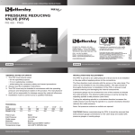
PRESSURE REDUCING VALVE (PRV)
D1725 - PN25
TELEPHONE: +44 (0)1473 277400
FAX: +44 (0)1473 277301
EMAIL: [email protected]
www.cranefs.com
FM311 ISO 9001
• Designed and manufactured under quality
management systems in accordance with
BS EN ISO 9001-2008
Every effort has been made to ensure that the
information contained in this publication is accurate
at the time of publishing. Crane Ltd assumes no
responsibility or liability for typographical errors or
omissions or for any misinterpretation of the
information within the publication and reserves
the right to change without notice.
CFS_PRV_0513
IOM_ OED16492N_v1
CRANE HOUSE, EPSILON TERRACE
WEST ROAD, IPSWICH
SUFFOLK IP3 9FJ
www.cranebsu.com
2
3
GENERAL NOTES OF SAFETY
1 The PRV must only be used:
• for the specified purpose
• if it is in satisfactory condition
• whilst taking the necessary safety and hazard precautions
2 Always read the installation instructions.
3 The PRV must only be installed in accordance with the operating
pressure and temperature stated on the product. The manufacturer
shall not be responsible for damage caused by external influences.
4 Installation must be carried out by a qualified individual.
INSTALLATION AND ADJUSTMENT
TECHNICAL
Note: Set pressure reduces as outlets are opened.
Size
Length (mm)
Weight in Kg
½”
135
1.2
Field of use:
Inlet Pressure:
Outlet range:
Materials:
End Connections:
Temperature range:
¾”
160
1.3
1”
180
2.4
1.1/4”
195
2.6
Water
Up to 25 bar
1 to 8 bar
Bronze
Male tapered BSEN 10226-2
Up to 80°C (WRAS) max
PRESSURE REDUCING VALVE (PRV)
1.1/2”
225
5.5
2
255
6.0
The PRV is pre-set to an outlet pressure of 3 bar and is to be installed
in the pipe without applying stress to the connections.
The flow direction must coincide with the arrow on the valve body. The
valve can be installed in any mounting position. The pipe should be
thoroughly flushed prior to installation of the PRV, to prevent small
particles entering and damaging the internal components.
A pressure gauge can be screwed into one of the sockets to indicate
the outlet pressure. The desired outlet pressure is set by turning the
adjusting spindle at idle pressure (zero flow).
Turning the adjusting spindle in a clockwise direction increases the
outlet pressure and turning the spindle in a counter-clockwise direction
reduces the outlet pressure.
CAUTION!! Before commissioning the PRV, it should be ensured that
both pressure gauge connections on the valve body are sealed with
pressure gauges or sealing plugs.
PRESSURE REDUCING VALVE (PRV)
4
6
INSTALLATION AND OPERATING INSTRUCTIONS
MAINTENANCE
CAUSE OF FAULTS, REMEDIAL ACTION
After long periods of inactivity the valve must be tested.
The non-return valve installed between PRV and water heater may be
leaking, which, during the heating process of the boiler, leads to the
expanding water of the boiler causing a rise in secondary pressure at the
pressure gauge although the pressure reducer is operating correctly.
The PRV should be regularly inspected in accordance with BSEN-1567.
a) Pressure gauge indicates pressure increase
CAUTION!! When carrying out maintenance on the PRV, the valve
should be isolated and the system pressure should be removed.
Remedial action: Replace non-return valve.
b) Damage to seat seal or sleeve
If the outlet pressure of the PRV increases or water discharges at the
upper part of the valve, this may be due to damage to the seat seal and /
or sleeve.
REPLACING THE VALVE INSERT
Remove plastic protective cap; loosen lock-nut. Relieve spring tension
by turning the setting spindle counter-clockwise. Unscrew spring
housing, spring plate, settling spindle, copper ring and spring. By
means of 2 screwdrivers lever-out the complete valve insert (fig 1) and
replace with a new one (fig 2). Installation is carried out in reverse
order.
5
Remedial action: Restore correct operation of the valve by replacing the
valve insert.
If water discharges at the spring bonnet, this may be because it is not
screwed on tightly enough.
7
CLEANING THE STRAINER
Unscrew and remove valve insert - see previous section (fig 1).
The strainer can be pulled off and cleaned after removing the bottom
O-ring from the valve insert. After cleaning, slide strainer over the valve
insert and insert O-ring back in the provided groove. Assemble
complete valve insert. Installation is carried out in reverse order (fig 2).
c) Scale (furring)
The distance to the non-return valve must be such that no hot water can
be applied to the PRV, even in the event of the fitting leaking.
If you do not apply this rule during the installation there is a risk of the
PRV scaling.
Remedial action: Correct the installation arrangement. If this is not
possible you must replace the complete valve insert regularly.
fig 2
fig 1
PRESSURE REDUCING VALVE (PRV)
PRESSURE REDUCING VALVE (PRV)