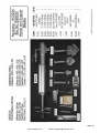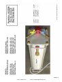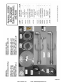
1
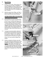
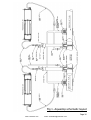
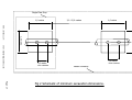
AQUASTOP MK2
Temporary flow stopping system for water mains
Operator Instructions
ISSUE 2 - 01/06/12
www.cranebsu.com
email: [email protected]
INDEX
TITLE
Page No.
Introduction
1.
1.
General Notes
2.
2.
Bag Setting
3.
3.
Support Blade Setting
5.
4.
Setting The Base
6.
5.
Manual Drilling
8.
6.
Bag Charger Unit Check and Prime
10.
7.
Double Stop Off procedure
11.
8.
Single Stop Off Procedure
13.
9.
Low Pressure Application
15.
Fig 1. Schematic Layout
16.
Fig 2. Excavation schematic
17.
Mains Sizing Table.
18.
Appendix A. Contents Labels
www.cranebsu.com
email: [email protected]
Introduction
Aquastop has been developed to stop water flow with minimal disruption. It has been
designed to provide an easy low cost solution to stopping flow in an operational pipeline.
Aquastop can be used to isolate piping systems for repair, alterations and renovation
and is suitable for most pipe materials including cast iron, ductile iron, steel, PVC, and
Polyethylene.
The system involves using an inflatable Sarco MKII Hydra Bag™ inserted into the mains
with specialist launch equipment through a small diameter access hole. The bag is then
inflated by means of water pressure from the main, through a specially designed bag
pressurisation unit The system comprises lightweight easy to use equipment, for small
mains at up to 8 bar pressure and flow rates up to 10 litres/sec.
The system is suitable for either single or double ended flow stopping operations.
Page 1
www.cranebsu.com
email: [email protected]
1. General notes
A. DO NOT OPERATE THIS EQUIPMENT UNLESS YOU HAVE BEEN TRAINED IN ITS USE AN HOLD
THE RELEVANT TRAINING CERTIFICATE ISSUED BY WASK
B. IF ANY OF THESE INSTRUCTIONS CONFLICT WITH THOSE OF YOUR EMPLOYER, YOUR EMPLOYERS INSTRUCTIONS MUST BE OBEYED.
C. ALWAYS CHECK THAT ALL PARTS ARE AVAILABLE AND IN GOOD WORKING ORDER BEFORE
COMMENCING WORK.
1.1
The flow stop equipment shall comply with the latest design and all the associated equipment
and fittings used during a stopping off operation shall be in sound working order.
1.2
When cut out work is carried out on jointed pipes, the thrust generated by the pressure in
the main acting on the bag may be high enough to uncouple non-restrained pipe joints. Consideration shall be given to restraining the pipe work by an approved method such as a transportable load bearing frame clamped to the main either side of the cut out section.
1.3
It is important to note that to stop off a main at an operating pressure in excess of 8 bar or
flow rate in excess of 10 litres/sec and where pressure or flow reduction is not practicable,
then it will be necessary to use an alternative stopping off system in accordance with approved codes of practice and manufacturers recommendations.
1.4
Before a programmed stopping off operation is undertaken, the operating pressure of the
main should be reduced to the lowest level at which adequate supplies can be maintained.
1.5
A work programme shall be prepared and should include schedules of all necessary safety
and operational equipment and of all operational procedures. This programme should include
contingency plans for the possibility of bag failure and the availability and operability of relevant upstream and downstream line valves.
1.6
Details of the general arrangement and critical dimensions are shown in Fig 1 and Table 1.
1.7
The drilling of the main, installation and subsequent removal of the bag support tubes and
plugging of the holes shall be carried out using an approved under pressure drilling machine.
1.8
An adequate bypass shall always be installed, unless it’s omission is specifically authorised by
the Engineer or his representative.
Page 2
www.cranebsu.com
email: [email protected]
2.
Bag Setting
2.1
Release Canopy Clamp. Whilst holding Canopy stationary push down on Bagtube to
expose threaded end of tube. Place the head
assembly down flat on the packing box and
rotate the bag tube handles until they are
horizontal and the cut out is orientated vertically. Re-clamp.
2.2
Bag tube cut out
Select the correct size of Bag , see Table 1.
Attach to Inflation tube and tighten to seal
using 16mm A/F open wrench provided.
Inflation tube
The Bag direction MUST be set BEFORE
being inserted into the main.
2.3
Rotate Inflation tube until the nose of the
bag points in the opposite direction to that
of the Cut out in the Bag tube. Release the
Direction indicator using the 5 A/F hexagon
T wrench and align the pointer with the
nose of the bag and then re tighten. At this
stage the bag can be liberally sprayed using
a WFBS. listed Silicon lubricant paying particular attention to the stitched joints. This
will enhance bag handling during launch and
recovery.
2.4
The bags are pressure tested, sealed and
packaged at the manufacturers and therefore no further pressure test is required before insertion. However your employers
procedures may require you to do a pressure test and this is best done at stage 2.3.
Using an air pump and the inflation/vent
adaptor.
2.5
Deflate the bag then fold down and withdraw bag into bag tube taking care to avoid
snagging at screwed end of actuating rod.
DO NOT rotate inflation tube relative to bag
tube once the direction of the bag is set.
This would cause the bag to twist resulting
in launching difficulties. Pull back the bag via
the inflation tube such that the bag nipple
retracts into the bag tube and is clear of the
cut out.
Actuating rod
Bag nipple
Canopy clamp
Direction indicator
Inflation tube Vent
Page 3
www.cranebsu.com
email: [email protected]
2.
Bag Setting Continued
NOTE! : Follow Section 3 to attach and set the
support blades the bag must be test launched
to ensure that no snagging has occurred during the two procedures.
2.6
To test launch, open blades and stand the
bag tube upright using the bag packaging to
rest the nose shoe on. Ensure the canopy
lock is on, drive down the inflation tube via
the direction indicator handles until the bag
emerges from the aperture in the nose shoe
and rests on the packaging.
2.7
To retract, pull up on the same handles. This
process can be repeated until the launch and
recovery is acceptable.
Chlorinating Bag
Note! : The bag can be chlorinated prior to its
final retrieval into the bag tube. Inflation at
this stage is optional.
2.8
Close the support blades. Unlock the canopy
clamp and slide the canopy down to a stop to
conceal the bag tube, re-lock. The AQUASTOP head assembly is now ready to be
loaded into the base.
Page 4
www.cranebsu.com
email: [email protected]
3.
Support Blade Attachment
3.1
Take selected Nose Shoe and with blades held
closed, offer the female thread of the actuator to the
actuating rod such that the Nose Shoe tongue and
Bagtube cutout are in alignment. Locate the 12mm
A/F hex ratchet provided onto hex drive of the actuating rod situated on top of the Bagtube and rotate
clockwise to attach the actuating rod to the Nose
Shoe.
3.2
Blade actuator
Engage large brass nut onto Bagtube by rotating
clockwise. Before assembly locks up from attaching
actuating rod in 3.1. ensure tongue and cut out is
located. As the nut is tightened the support blades
will open out. This is achieved by the Actuating pin
locating in the blade slots effected by a down wards
movement. IMPORTANT! Do Not allow this pin to
bottom out in the slots otherwise it will become over
stressed and fail. The pin position is adjusted by rotating the actuating rod clockwise to raise and anticlockwise to lower using the 12mm A/F hex ratchet
provided. The large nut should be tightened up to a
stop, use the Pin wrench provided.
Tongue and cutout
Brass nut
The Blades MUST be set BEFORE being
inserted into the main.
3.3
With the Nose Shoe attached the Blades should be
fully open and the pin positioned near to the bottom
of the blade slots. Adjust if necessary as described in
3.2. Check blade operation by attaching the Actuating
Cam onto the hex drive such that the minimum side
is situated adjacent to the top face of the Bagtube.
Fix in place using the captive pin such that 180°cam
operation can be achieved. Carefully operate cam to
raise the support blade pin, which on full stroke will
close the blades fully with the pin situated at the top
of the blade slot, adjust if necessary.
Pin wrench
Support blade
pin at top of
blade slot
Nose shoe
Note! The actuating rod is spring loaded and care
should be taken upon opening the blades to avoid
trapping by the cam handle.
Actuating Cam
12 A/F hex ratchet
Page 5
www.cranebsu.com
email: [email protected]
4.
VJ EasiTap Saddle
Setting the Base
A. Metallic & PVC pipes, see paragraphs 4.1-4.8
B. Polyethylene pipes, refer to manufacturer.
4.1
Use a wire brush to ensure pipe surface is
clean and free from loose soil or rust. The
pipe surface should be free from deep pits or
holes.
4.2
Select the correct Viking Johnson EasiTap
Saddle to suit the outside diameter of the
pipe. The size range is marked on each saddle.
4.3
Follow the installation instructions supplied
with the EasiTap Saddle, ensure threaded
outlet is vertical.
4.4
Remove the closure cap and plug from the
saddle and store in a safe place.
4.5
Take the Aquastop Base unit and check that
the O-Ring is in position and is free from
damage.
4.6
Fit Base unit to the outlet thread on the EasiTap Saddle and rotate clockwise to tighten.
O-Ring Seal
Note:- The Base unit may finish pointing
randomly, this is OK for Bypass positions.
For bagging positions the base must line up
with the main with the Plastic Cap facing
towards the working section.
Plastic Cap
Page 6
www.cranebsu.com
email: [email protected]
4.
Setting the Base - Continued
4.7
Rotate the Base unit Anticlockwise until the
Base unit lines up as indicated.
Note:- It should not need to be rotated
more than 1 turn.
4.8
Pull the Strap around the pipe and hook the
Anchor yokes/bolts in to the arms of the
Base unit. Pull the strap to remove the slack
as this will reduce time in tightening the
nuts.
4.9
Tighten the nuts evenly. DO NOT OVER
TIGHTEN. A moderate tightening torque between 20 and 30 Nm will ensure satisfactory
anchorage. Use the 24 A/F hex ‘cast’ ring
spanner provided.
4.10
Using the other end of the spanner in 4.9
(12.7 A/F sq. socket), turn the Pivot stud to
operate the Valve Plate in the base unit.
Check that the valve plate is undamaged and
works smoothly.
Leave the Valve Plate in the open position.
Page 7
www.cranebsu.com
email: [email protected]
5.
Manual Drilling
5.1
Fit the 56mm Cutter into the Carrier and tighten nut
using 19mm A/F socket provided.
5.2
Fit the Carrier to the Drill Spindle ensuring that the
flats on the Carrier engages the slot in the spindle.
Tighten the set screw to retain the Carrier using the
T-handle wrench. Fitting a small magnet placed inside
the shell will facilitate retention of the drill coupon.
5.3
Fit the Spindle fully into the Drilling head with the Cutter inside the “bell” of the Drilling head. The Drilling
head should always be lifted by both the Drill Spindle
and Bridle.
NOTE: THIS IS A SAFETY FEATURE.
Nut
Magnet
Set screw
and wrench
Ensure the Vent Lock spindle is in the OPEN position
with the handle pointing away from the base. Using
the large spanner, fit the drilling head into the bayonet
of the base unit turning clockwise to a stop and then
rotate the vent lock spindle clockwise to lock the drilling head in position.
NOTE: THIS IS A SAFETY FEATURE.
5.4
Check that the Valve Plate is open (indicated by the
pivot stud pointing away from the center of the machine). The Base unit has a pressure Equalising Valve
identified by a blue handle for high pressure operation.
Check that it is in the closed position indicated by the
cast word “press” exposed on the base unit.
Vent spindle in
open position.
SAFETY NOTE: Your employer procedures may
require you to perform a pressure test at this
point. The canopy is fitted with a ball valve for
this purpose.
5.5
Slowly lower the Spindle down until the Cutter is in
contact with the pipe. Fit the Ratchet Spanner, ensuring it will drive clockwise. Swing over the Bridge and
locate Feed Screw button into the dimple of the drill
spindle.
5.6
Whilst turning the Spindle with the Ratchet Spanner,
gradually feed the drill via the Feed Screw. Moderate
force should be used as too much will damage the
Cutter and make Spanner operation difficult.
Page 8
www.cranebsu.com
email: [email protected]
5.
Manual Drilling - Continued
5.7
Once the Cutter has penetrated the pipe wall it will
become easier to rotate the Ratchet. Continue drilling
for at least 1 to 2 turns of the Feed Screw, particularly
if the main is lined as this will ensure the cut is complete.
5.8
Feed screw
Bridge
The Feed Screw can now be reversed by turning anticlockwise until the Drill Spindle has reached it’s stop
and the Bridle can be released.
SAFETY NOTE: The mains pressure will try to
force the Drill Spindle upwards, this must be
restrained by using the Feed Screw in order to
avoid serious injury.
5.9
Close the Valve Plate by rotating the Pivot Stud anticlockwise, the slot on the Stud should noe be pointing
to the center of the machine. Ensure the Equalisation
Valve is closed.
5.10
Open the Vent Lock by rotating anticlockwise. Water
pressure will be release through the valve and when
the pressure has dropped to zero the Drilling Head
may be removed.
Vent valve open
SAFETY NOTE: Continuous venting of pressure
from the Valve indicates leakage past the Valve
Plate or an open Equalisation Valve. Check both
are closed and it this does not resolve the problem do not attempt to remove the Drilling Head.
Close the Vent Lock and seek technical advice.
5.11
Use the large Spanner to remove the Drill Head.
5.12
Removed the drilled out coupon from the cutter, clean
up and re-attach the magnet ready for the next operation. Replace the Cutter if damaged or worn.
Coupon retained by magnet
Page 9
www.cranebsu.com
email: [email protected]
6.
Bag Charger Unit check and prime.
6.1
This procedure can be carried out having first installed the standpipe. Ensure all bypass outlets are
shut or capped as necessary. Attach the female end
of the blue hose to one of the two male connectors
on the bag outlet manifold of the Bag charger and
close the adjacent valve. Attach the male end of the
blue hose to the remaining available outlet snap connector on the standpipe (the other will be occupied
by a pressure gauge).
6.2
Unscrew the filler cap situated on top of cylinder and
add a chlorinated solution suitable to treat 9 litres.
SAFETY NOTE: Chlorine is a hazardous substance.
Consult your employer procedures for the handling
and use of chlorine.
Bag outlet
Manifold
colour red.
Filler cap
Blue hose on bag outlet
connector
12.1
Drain valve
Open inlet valve to fill air space in cylinder, do not
allow chlorinated water to spill out of filler. Close
valve and replace filler cap to provide a pressure seal.
6.3
Reopen valve and check filler cap is leak tight. At the
other end of the unit push a short hose onto the hose
connector of the drain valve; open drain valve. The
piston assembly within the unit will travel to a stop
due to the water pressure in the main. Water or air
(initial priming) issuing from the drain valve indicates
piston movement.
6.4
When this ceases turn off the drain valve and the
blue hose valve.
6.5
Swap over the blue hose from the bag outlet connector to the mains water inlet manifold via the male
snap connector adjacent to the drain valve. Ensure all
valves on the unit are shut.
6.6
6.7
Attach the Red feed Hose to one of the connectors on
the bag outlet manifold. To purge air from the hoses
open all three hose valves. Taking the male end of
each of the red hoses depress the end to dispel any
air trapped in the hose, the hoses are now primed.
The blue hose was purged at stage 6.2. Close all
valves prior to start of the flow stopping operation.
Mains water inlet
Manifold colour blue
Blue hose
12.5
Bag feed hoses coloured red.
The Pressure Gauge assembly can be ‘snapped into
the Filler Cap assembly. This will enable Bag Pressure
to be monitored.
The Bag Charger unit and hoses are now primed for use.
www.cranebsu.com
12.3
12.6
Bag outlet manifold
Colour red
email: [email protected]
Page 10
7. Double stop off procedure
7.1
From Table 1 mark out the positions for the four saddles, two either side of the intended cut.
Attach all the saddle & base units. At the upstream bypass point drill the main, then take a pressure reading at this point. Note! A pressure gauge can be attached to the valve on the drilling
head for this purpose. If satisfactory the operation can proceed.
7.2
Attach the bypass standpipe. Attach Pressure gauge supplied to one of the snap connectors on
the standpipe. Do not open Plate Valve!
7.3
At the downstream bypass position repeat steps 7.1 – 7.2.
7.4
At the upstream bag insertion position attach the Drilling Head and drill main. Recover the drill
coupon remove drilling head leaving base valve in the closed position.
7.5
Repeat step 7.4 at the downstream bag insertion position.
7.6
Remove the Bypass Hose end caps and attach one end of the Hose to the upstream Standpipe.
Open the Plate Valve at that point and flush out the Hose, when satisfactory, close the Valve
plate and attach free end to downstream Standpipe. Open both Valve Plates fully.
The Bypass is now in service
7.7
Fit a previously prepared AQUASTOP head into the upstream Base unit adjacent to the Standpipe
position. Attach the Recharge hose to the 1” outlet on the Standpipe and flush out. When satisfactory attach free end to the 1” outlet on the Canopy. Fit the torque arm to the canopy.
7.8
Fit the remaining prepared AQUASTOP head into the downstream Base unit and attach the Vent
Hose on to the 1” outlet on the Canopy.
7.9
Attach Blue feeder hose to the remaining snap connector on the Standpipe and prime the Pressurisation Unit as detailed in section 6.
7.10
Repeat at other Standpipe for second Pressurisation unit.
7.11
Open upstream Valve Plate, lower the BAGTUBE into main and check alignment, release and
open BAG SUPPORT BLADES, set then lock the BAG TUBE CLAMP.
7.12
Attach the Vent Adapter and using moderate force push down the Inflation Tube to launch bag
upstream into the main. The Inflation Tube when free will, tend to rise against mains pressure,
hold in place using strap provided. Replace the adapter with the male end of a Red Hose and
inflate the bag. NOTE! At this point, the main will be shut off and all flow downstream will be
supplied by the bypass pipe. Upstream and downstream pressure readings should be taken at
this point to ensure that, the bypass has sufficient capacity to support downstream demand and
there is no substantial pressure drop across the bag. If a pressure drop has developed seek tech-
nical advice.
Page 11
www.cranebsu.com
email: [email protected]
7. Double stop off procedure continued
7.13
Open downstream Valve Plate, lower BAG TUBE into main and check alignment, release and
open BAG SUPPORT BLADES, set then lock the BAG TUBE CLAMP.
7.14
Attach the Vent adapter and using moderate force push down the Inflation Tube to launch bag
downstream into the main. Hold Inflation Tube in place using strap provided. Replace the
adapter with the male end of the second Red hose and inflate the bag using the second Pressurisation unit.
Allow 5 minutes for conditions to stabilise, monitor both pressure gauges.
7.15
Ensure that the RECHARGE VALVE is closed and open the downstream VENT VALVE to de-pressurise the working section between the bags. Allow the water escaping to discharge to waste. At
this point the canopies may move, this is normal and indicates that the bags have seated against
the internal support.
Allow 10 minutes for conditions to stabilise.
Note! If there is excessive leakage issuing from the Vent Hose, the bags may be deflated and
repositioned to achieve an improved seal. Do this by first closing the VENT VALVE to allow the
working section to re-pressurise, deflate the bags, see step 7.17 and then repeating steps 7.12 &
7.14. Once a satisfactory leakage is obtained the main can now be opened and drained for repair
work to commence.
To remove equipment & reconnect main.
7.16
On completion of the repair work the working section may be filled, flushed, disinfected & pressure tested by opening the RECHARGE VALVE and controlling water flow with the VENT VALVE.
7.17
Once at mains pressure, de-pressurise the downstream bag by closing the blue hose inlet valve
and opening the pressurisation unit vent valve. When water ceases to flow from the vent valve
the bag can be recovered into the bag tube.
7.18
Close SUPPORT BLADES, unlock canopy clamp and lift the BAG TUBE back into the AQUASTOP
head, close the valve plate & vent the head.
7.19
Repeat above operation for the upstream equipment.
7.20
Close bypass valve plates, remove recharge pipe & bypass pipe from standpipe. Disconnect pressurisation units & remove standpipe. Pack away all hoses, standpipes & pipe work.
7.21
Fit appropriate completion plug to fitting spindle, fit spindle into drilling head and install plug into
the saddles. Vent head and check for leak tightness, adjust if required, remove base unit, clean
and place in box. Repeat at other position.
7.22
Remove the AQUASTOP heads from the base units, remove the bags and discard, place equipment in box. Repeat step 7.21 at each location.
7.23
Clean threads on saddle outlets and fit completion caps.
The operation is now complete.
www.cranebsu.com
email: [email protected]
Page 12
8.
Single stop off procedure
8.1
From table 1 mark out the positions for the two saddles on the upstream side of the intended
cut. Attach drilling machine at the standpipe take off point and cut an appropriately sized tapping. Take a pressure reading at this point. Note! A pressure gauge can be attached to the valve
on the drilling head for this purpose. If satisfactory the operation can proceed.
8.2
Attach a Type A bypass standpipe. Attach Pressure gauge supplied to one of the snap connectors
on the standpipe and close off the 2“ bypass outlet using the 2” CAP provided. Do not open valve
plate!
8.3
Fit a base unit at the bag insertion position and drill. Recover the drill coupon remove drilling
head leaving base valve in the closed position.
8.5
Fit a previously prepared AQUASTOP head into the base and attach the recharge hose to the 1”
outlet on the standpipe and flush out. When satisfactory attach free end to the 1” outlet on the
canopy. Open the VENT VALVE on the canopy and the RECHARGE VALVE.
8.6
Attach blue feeder hose to the remaining snap connector on the standpipe and prime the pressurisation unit as detailed in section 6.
8.7
Open valve plate, lower BAGTUBE into main and check alignment for upstream deployment,
release and open BAG SUPPORT BLADES, set then lock the BAG TUBE CLAMP.
8.8
Attach the inflation tube adapter and using moderate force drive down the inflation tube to
launch bag upstream into the main. The inflation tube when free will, tend to rise against mains
pressure, hold in place using strap provided. Replace the adapter with the male end of a red
hose and inflate the bag. NOTE! At this point, the main will be shut off and any flow downstream
will be supported by the recharge hose. On a single stop off the only flow demand will be from
leaks up to the dead end. Allow 5 minutes for conditions to stabilise.
8.9
Close the RECHARGE VALVE at the standpipe and close the canopy valve. Uncouple the recharge
hose at the standpipe end (care should be taken as the hose will be pressurised). Open the canopy valve and de-pressurise the working section downstream of the bag. Allow 10 minutes for
conditions to stabilise. Note! If there is excessive leakage issuing from the vent hose the bags
may be deflated and repositioned to achieve an improved seal. The main can now be opened
and drained for repair work to commence.
To remove equipment & reconnect main.
8.10
On completion of the repair work the working section may be filled, flushed, disinfected & pressure tested. Reattach the recharge hose to the standpipe and open the valve controlling water
flow with the VENT VALVE on the canopy.
8.11
When satisfactory de-pressurise the bag by closing the blue hose inlet valve and opening the
pressurisation unit outlet drain. When water ceases to flow from the vent valve the bag can be
recovered into the bag tube.
Page 13
www.cranebsu.com
email: [email protected]
8.
Single stop off procedure continued
8.12
Close SUPPORT BLADES, unlock canopy clamp and lift the BAG TUBE back into the AQUASTOP
head, close the valve plate.
8.13
Close standpipe bottom valve and with the recharge hose still attached and communicating to
the bag canopy de-pressurise the standpipe, hose and canopy via the base unit vent valve. Disconnect the pressurisation unit & remove standpipe. Pack away all hoses, standpipe & pipe work.
Remove bag canopy and remove nose shoe. Recover bag and discard. Pack away Canopy and
nose shoes.
8.14
Fit appropriate completion plug to fitting spindle, fit the spindle into drilling head and install plug
into the saddle. Vent head and check for leak tightness, adjust if required, remove base unit,
clean and place in box. Repeat at other position.
8.15
Clean threads on saddle outlet and fit completion cap.
The operation is now complete.
Page 14
www.cranebsu.com
email: [email protected]
9. Low Pressure application
9.1
During pressurisation of each Bag, pressure will register on the Gauge
assembly on the Filler Cap. For pressures less than 3.0 bar it may be
necessary to increase Bag pressure via a Hydraulic Pump to effect
a shut off.
9.2
If the Upstream Bag Pressure is less than 3.0 bar and the working
section cannot be de-pressurised go to next step.
9.3
Using a suitable Hydraulic Pump fill the Pump Reservoir. This can be
done by Opening the Vent Valve on the Upstream Bag Charger.
Mains Water will flow from the Vent Hose. When complete close
the Vent Valve.
9.4
Disconnect the Blue Hose from the Outlet Connector of the Upstream
Stand Pipe and attach to the Pump Outlet.
9.5
Operate the Pump to increase Bag pressure indicated by the Bag
Gauge to a maximum of 3.5 bar. Isolate the Pump.
9.6
Repeat steps 9.2 - 9.5 for the Downstream Bag.
9.7
After a few minutes allowing for the system to settle de-pressurise
the working section.
9.8
On completion of the work de-pressurise and recover the Bags in
the normal manner.
Page 15
www.cranebsu.com
email: [email protected]
Fig 1. Aquastop schematic layout
Page 16
www.cranebsu.com
email: [email protected]
Single Flow Stop
1,0 metre
2,0 -15,0 metres
1,0 metre
1,0 metre
1,0 metre
www.cranebsu.com
email: [email protected]
0,6 metre
Drill Centres
0,6 metre
Drill Centres
Double Flowstop
Page 17
Fig 2 Schematic of minimum excavation dimensions.
Page 18
www.cranebsu.com
email: [email protected]
Page 19
www.cranebsu.com
email: [email protected]
Page 20
www.cranebsu.com
email: [email protected]
Page 21
www.cranebsu.com
email: [email protected]
Page 22
www.cranebsu.com
email: [email protected]
www.cranebsu.com
email: [email protected]