1
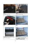
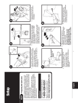
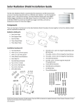
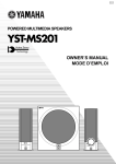
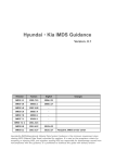
Movement Sensor Switch
Thank you for purchasing the Movement Sensor Switch. With this step
towards energy efficiency you have joined the increasing number
people who prefer green and smart living.
Packing contains:
User Manual: Please
read this manual
before using
product.
Cutting Template
for false ceilings:
Use this for accurate
marking of cuts in
false ceilings
Mounting Screws:
(Provided in a
sachet) Both selfthreading screws and
nut-bolts are
provided. Use
appropriately for
different types of
false ceiling
material.
Movement Sensor:
Concealed fit type
for false ceilings and
RCC Ceilings.
MS201 Series Product Manual
© Ideas Unlimited, Mysore
1
Product description
S ta tu s
In d ic a tors
Status Indicators:
P
Power
(White)
S
Sense (Blue)
L
Load (Red)
M ou n tin g H o le
SENSOR
6 Min
P
S
Off Timer: 2 Minutes or 6 Minutes.
2 Min
OFF
TIMER
L
Mounting holes: Mount the unit to
ceiling using this.
M o u n tin g H o le
Figure 1: Front view
Mains Connector:
Recommended: 230V AC, 50HZ
(110V-230V Wide range)
M a in s
C on n ec tor
Lo a d
C o nn e c to r
F u se /
H o ld er
Load Connector:
Recommended: 600W load max.
Fuse: 6A Glass fuse in socket
Figure 2: Back View
Internal Wiring reference
(Isolated)
MS201 Series Product Manual
© Ideas Unlimited, Mysore
2
Technical Specification
Parameter
Sensor Range:
Operating
Voltage
Load Capacity:
Unit Dimensions:
Off Timer
Options:
Power
Consumption
Safety Features:
Value
MS201-W6A: 20'X20' maximum
MS201-M6A: 14'X14' maximum
MS201-N6A: 08'X08' maximum
110-230V AC, 50-60Hz
(Wide Voltage range)
600 Watts Maximum
Product: 60 x 67 x 60 mm
Mask: 120 x 100 mm
2 Minutes for areas with high activity
6 Minutes for areas with low activitiy
Standby mode: 50-100 milli-Watts
Active mode: 350-450 milli-Watts
1) 6A Glass Fuse (user-replaceable) present
to prevent short-circuit/overloading
2) Higher rating connectors and contacts for
safety and reliability.
3) Shock proof (end user useable) connectors
4) Complete electrical isolation between
Sensing and switching circuit
Using the cutting template to mark on false ceilings
C u ttin g
Te m p la te
F a ls e
C e ilin g
Figure 3: Using the cutting template for marking on ceiling
1.
2.
3.
Place the cutting template on false ceiling with the
printed markings facing downwards from the ceiling.
(See instructions on the cutting template)
Mark the slot and two mounting holes using a pencil.
Mounting the unit: If material is hard (Gypsum etc),
use self threading type screws to mount the unit. If
MS201 Series Product Manual
© Ideas Unlimited, Mysore
3
the false ceiling material is thin (thermo coal or
similar material) use the nuts and bolts to mount.
Sensor coverage area
The sensor used is a passive sensor. It does not emit any light or any
form of energy). It focuses Infra-red emitted by surroundings on to an
IR sensitive photo cell. Based on the model of your unit, the range is
specified below.
Sensor
Wide
Medium
Narrow
Coverage Area
(20’X20’ approx.)
basement, parking
lots etc.
Typical room
(14’X14’ approx.)
Zone within a
typical room.
(8’X8’ approx.)
Illustration
Models
MS201-W6A
MS201-M6A
MS201-N6A
Simple Installation
Schematic below indicates how to connect the unit in a simple
configuration where the device controls only one load.
SWITCH
PHASE
NEUTRAL
Figure 4: Schematic for simple installation to control one device
MS201 Series Product Manual
© Ideas Unlimited, Mysore
4
Note: We recommend you to retain the switch in your wall for the
lighting so that it helps in complete switching off of the lights and the
movement sensor unit.
Advanced Installation retaining existing switches
The unit is also designed to seamlessly integrate into your existing
electrical wiring and control selected electrical appliances in a typical
room. The Schematic below shows how to install the unit in a room
with existing wiring and switches.
L
N
DP SWITCH
NEUTRAL (COMMON)
Figure 5: Installation retaining the switches on all appliances
The unit can control up to 600W load.
MS201 Series Product Manual
© Ideas Unlimited, Mysore
5
Recommended Location of Sensor in a room
The diagram below shows the typical location of installation in a room.
Figure 6: Typical installation in a room
To install retaining existing switches, you may have to draw 3 or 4
wires (depending on load) from the ceiling to the switch board. In the
switch board, the wiring can be configured to use existing switches to
control the lighting. This allows retaining all existing switches in the
switch board for individual control, still being able to save energy.
Timer Selection
Setting
2 Mins.
6 Mins.
Capacity
Corridors, low usage spaces, or places
used by many people.
Work areas, Office cubicles, very few
people presence in the sensor zone
Power Consumption
Standby mode: 50 mili-watts
Active mode: 350-450 mili-watts
MS201 Series Product Manual
© Ideas Unlimited, Mysore
6
Application Ideas
Energy Saving:
1.
Corridors of large buildings with less usage
2.
Cubicle Areas, Cabins of offices
3.
Conference rooms in office buildings, public buildings
4.
Parking lots of Apartment complexes
5.
Common Areas of Apartment complexes
6.
Rest rooms and Washrooms in hotels, public buildings,
office buildings
7.
Basement areas of Apartments and basements
8.
Basements and narrow corridors of Shopping centers
9.
Lab Area, any kind of activity areas in large buildings,
factories.
Security:
1.
Outdoor lighting in compounds of houses
2.
Outdoor lighting in hotels, public buildings
3.
In front of Basement door
4.
Basements and narrow corridors of Shopping centers
Elder Care/Child Care:
1.
Switch on narrow corridor lights as soon as someone enters
the zone
2.
Switch on bathroom lights automatically on entry, conserve
energy when not in use
3.
Switch on lights outside the house as someone walks by
within the compound
4.
Switch on lights in bedroom when someone gets out of bed
MS201 Series Product Manual
© Ideas Unlimited, Mysore
7
Our Commitment
Green: Technologies that are environment friendly
Economical: Reduce cost of usage
Smart Living: Enhanced living experience
Authorized Distributor/Dealer
Designed, Manufactured in India by:
111/V, Emerald Enclave, Hebbal Industrial Area
Mysore – 570 018
www.ideas-unlimited.in
Tel/Fax: 0821-2402979
MS201 Series Product Manual
© Ideas Unlimited, Mysore
8