Download BWA-SS-10 - Nordic Europe
Transcript
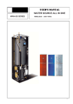
USER’S MANUAL
SERO
BWA-SS-10
1
List of contents
1
Important Information……………………………………………………..3
1.1
1.1.1
Safety Instructions………………………………………………………………..3
Installation and Maintenance……………………………………………………...3
1.1.2
1.1.3
1.2
1.2.1
Modification of System Components……………………………………………….3
Safety Valve……………………………………………………………………...3
Protective Measures…………………………………………………………..…..3
Preventing Corrosion……………………………………………………………...3
2.1
2.2
2.3
2.4
Heat Pump Principle………………………………………………………..….4
Auxiliary Heater – Electric Heating Element…………………………….....….5
Water Heater……………………………………….…………………….....….5
Control Panel………………………………………………………….….....….6
2
Unit Description……………………………………………………….…….3
Functions………………………………………………………….……….....….7
Operating Instructions……………………………………….……….....…..7
3.1
General Information……………………………………….……….....………..7
3.1.1
Menu Navigation……………………………………….………....................…..7
3.1.1.1 Display of current operating mode …………………………………….....…..7
3.1.1.2 Symbols……………………………………………………………...….....…..8
3.1.2
Menus……………………………………………………………...….....…...9
3.1.2.1 Main Menu INFORMATION………………………………………………...….......9
3.1.2.2 Sub-Menu OPERATION ………………………………………………...….....…..9
3.1.2.3 Sub-Menu HEAT CURVE………………………………………………...….....….10
3.1.2.4 Sub-Menu TEMPERATURE………………………………………………...….......11
3.1.2.5 Sub-Menu OPERATING TIME……………………………………..……...….....….11
3.1.2.6 Sub-Menu LANGUAGE…………………………………………………..….....….12
3.1.2.7 Sub-Menu RESET……………………………………………..………...….........12
Adjustments to be made regularly……………………………………...........12
3.2
3.2.1
Heat Generation – General………………………………..………...…..............12
3.2.2
Adjustment of the CURVE value………………………………..………...…........13
3.2.3
Adjustment of ROOM value………………………………..………...……..........13
3.2.4
Adjustment of Part of the Heat Curve…………………………………....…........14
3.2.5
Adjustment of the MIN and MAX value…………………………………....….......14
3.2.6
Adjustment of the HEAT STOP value…………………………………....…..........15
3.2.7
Graph of recent changes in TEMPERATURE…………………………….....…........16
3.3
Maximum Return Line Temperature…………………………….....…...........16
3.4
Warm Water Production………………………………..………….....…........16
3.5
Regular Checks…………………………………………………........…........16
3.5.1
Check of Operating Mode……………………………..........................…........16
3.5.2
Checking the Brine Level in the Brine sytem…………………………….....….....17
3.5.3
Checking the Water Level of the Heating System…………………………...….....17
Checking the Safety Valve…………………………….....………………….......18
3.5.4
3.5.5
In the Event of Leakage………………………………......………………….......18
4
Trouble shooting…………………………….....…………………..............18
4.1
Alarm Messages…………………………….....…………………..................18
5
Terminology and Abbreviations…………………………….........….......19
6
Default Settings………………………….....…………………..................20
7
References………………………….....…………………..........................20
2.4.1
3
2
1 Important Information
*If the installation will be shut down during the winter months, the heating system should be emptied of water to
avoid any damage due to freezing. (Call your Installation Contractor for help, see ”References” on page 20).
* The installation is practically maintenance free, but some monitoring will be required (see ”Operating
Instructions” on page 9).
* Before making any adjustments of system parameters, first find out, what the consequences are in each case.
* For all service work, please call your installation contractor.
1.1 Safety Instructions
1.1.1
Installation and Maintenance
Installation and commissioning as well as repairs and maintenance must be carried out by a qualified installation
contractor (see ”References” on page 20).
Any changes in the electrical installation must be undertaken by a qualified electrician (see ”References”on page
20).
Service work on the refrigerant circuit must be carried out by a qualified refrige- ration technician (see ”References”
on page 20).
Danger to Life!
1.1.2
Modification of System Components
The below components can only be modified by a qualified installation contractor:
*
Heat Pump Unit
*
Refrigerant, Brine sytem, warm water and power lines
*
Safety Valve
No structural changes may be made to the installation that might affect the operational reliability of the heat
pump.
1.1.3
Safety Valve
The following safety instruction s must be observed in regard of the safety valve of the heating circuit and the
overflow pipe:
*
Never close the connection between safety valve and overflow pipe.
*
When heated, water tends to expand which causes some water to be let out through the overflow pipe. This water
may be hot! The overflow pipe should therefore discharge into a floor drain placed so that nobody can get hurt.
1.2 Protective Measures
1.2.1
Preventing Corrosion
To eliminate any risks of corrosion, the use of all kinds of aeorosol should be avoided in the proximity of the heat
pump. In particular, avoid the following:
*
Solvents
*
Detergents containing chlorine
*
Paint
*
Glue
2
Unit Description
In order to get the best results from the climate system BWA-SS -10 you should read
through the section For the System manager in these Installation and Maintenance instructions.
BWA-SS-10 is a climate system for heating houses and apartment buildings as well as industrial properties.
Ground, rock or lakes can be used as the heat exchange source.
BWA-SS-10 is a complete heating installation for heating and hot water.
It is fitted with new design on the market to be developed specifically for heat pumps. A new evaporator enables a
new and improved circulation system for the refrigerant. The heat pump has an integrated 150 or 200 litre water tank and
3
an immersion heater. The Tap Water Stratification system improves the efficiency of heat transfer by keeping the water in
distinct thermal layers in the water tank.
The unit is fitted with a regulating computer, which is controlled over a graphic display unit.
Heat is distributed throughout the house over a hydronic heating system referred to as low temperature
system with a maximal water temperature to radiators (supply line temperature) of 65°C. Most of the heating
demand is taken care of by the heat pump (compressor unit), the auxiliary heater being started only when
demands exceed available heat pump capacity.
BWA-SS-10 consists of five main components:
a. Heat Pump Unit
Rotory or Scroll-compressor
Stainless steel heat exchangers
Circulation pumps for Brine sytem (brine) and heating systems
Valves and safety equipment for refrigerant system, complete with necessary electric components
b. Water Heater
150 or 200 litre
Lined with copper sheet against corrosion or made of stainless steel
Maintenance free as no anode is used
c. Reversing Valve
Opening or closing the connection to water heater according to operating mode: heating or warm water production
d. Auxiliary Heater
3/6/9 kW electric heating element
Three-step capacity control
Fitted on supply line
Delivers back-up heat in case of great heat demand that exceeds heat pump capacity
Starts automatically, provided operating mode “AUTO” has been selected
e. Regulating Equipment
The regulating system controls heat pump components (compressor, circulation pumps, auxiliary heater and
reversing valve). Based on data received from sensors, it starts or stops heat pump operation and determines
whether heating or warm water shall be produced. The system consists of:
Control computer with graphic display unit
Temperature sensors (outside air,room, supply line, return line,and Brine sytem)
2.1 Heat Pump Principle
A heat pump can exploit the energy contained in natural heat sources. Or, to put it differently, the heat
pump ”collects” heat energy from the heat source. This makes the heat pump a very environmentally friendly and
economically sound alternative for space heating.
a. A hose filled with liquid (Brine sytem) is immersed into a lake, dug into the ground or sunk into the rock. The
Brine sytem absorbs the heat energy of the heat source so that the temperature of the water circulating in the
hose is raised a few degrees.
b The Brine sytem is circulated to the heat pump’s evaporator. Here the heat energy of the Brine sytem causes the
refrigerant, circulating through the evaporator, to boil and turn into a gas – it evaporates.
c The refrigerant, having absorbed heat energy, is circulated to the compressor where pressure and temperature
are raised.
d The refrigerant continues to the condenser. When condensing, it releases heat energy to the heat carrier,
circulating through the condenser. The temperature of the refrigerant sinks, and it returns to its liquid state.
e
The heat energy released is carried by the heating circuit to water heater and radiator or floor heating systems.
f At last the refrigerant is led through the expansion valve, where its pressure is reduced, and then continues to the
evaporator. The process is restarted.
The heat pump has three separate liquid circuits
4
The heat pump has three separate liquid circuits
Brine sytem circuit – a water-based mixture (brine) transporting energy from heat source to heat pump.
Refrigerant circuit – circulating inside the heat pump. Through evaporation, compression and condensation it
absorbs energy from the Brine sytem and releases it to the heat carrier. The refrigerant is chlorine-free.
Heating circuit – water transporting heat energy to the heating system (radiators/floor coils) and the water
heater.
2.2 Auxiliary Heater – Electric Heating Element
The auxiliary heater – an electric heating element fitted on the supply line – has three capacity steps:
Step 1 = 3 kW
Step 2 = 6 kW
Step 3 = 9 kW
2.3 Water Heater
BWA—SS-10 comes with a built-in water heater holding 150 or 200 litres. The temperature of the water sent to
the water heater is controlled by the regulating pressure switch and cannot be adjusted. Warm water production is
stopped when the regulating pressure switch reaches its operating pressure, which corresponds to about 50-55°C warm
water temperature. At regular intervals the water in the water heater will be heated to as much as 65°C as a preventive
measure against bacteria. The preset interval is 14 days. For more information, please refer to ”Warm Water Production”
on page 16.
5
BWA-SS,BWB-SS
2.4 Control Panel
The control panel of BWA-SS features a graphic display, six control buttons.
Beside the control panel you will find the User’s Manual, a short description of how to increase and reduce room
temperature, and a label with name and phone number of dealer.
Graphic display
6
Control Buttons
(influence key)
2.4.1 Functions
The control computer is operated with the help of a user friendly menu system that is displayed on the control
panel. There is a main menu and four sub-menus accessible from the main menu. The menus are described in detail
further down.
To be able to select the desired menu and increase or reduce preset values, you will use the five buttons.
•
One button pointing upwards marked with a plus
•
One button pointing downwards marked with a minus
•
One button pointing to the right
•
One button pointing to the left
•
One button pointing to the ON/OFF
3
Operating Instructions
3.1 General Information
3.1.1
Menu Navigation
The right-hand button on the control panel is used to open the desired menu. The left-hand button is used to return
to the previous menu. The up and down buttons are used to navigate between the parameters of a menu. A cursor
(arrow) on the left-hand side of the display indicates which menu can be opened. The up and down buttons are also used
if you wish to increase or reduce a preset value.
3.1.1.1 Display of current operating mode
During normal operation, the following information will be displayed:
• Desired (preset) room temperature
• Whether there is a heating demand or not. If there is, there will also be symbols
telling which heat source is working– heat pump or auxiliary heater –
or both (see ”Symbols” on page 8).
• Which operating mode has been selected In addition to this, the following messages may be displayed:
• PHASE SEQUENCE
The compressor in the heat pump is running in the wrong direction, which means that heat is produced by the
auxiliary heater only (see ”Alarm” on page 18).
• HIGH RETURN
The temperature of the water returning from the radiators is too high so the heat pump will not be allowed to
7
produce heat. (see ”Alarm” on p. 18).
• START
The heat pump is in the processs of starting. There is a 30 second delay bet- ween start of Brine sytem pump and
compressor.
• START_MIN
The heat pump will start in the number of minutes indicated in the display.
3.1.1.2 Symbols
For you to know at a glance the actual operating mode of the heat pump, one of the following symbols will be shown in the lower part of
the display depending on which part of the unit is working:
The heat pump is running.
The auxiliary heater is activated. The figure next to the symbol indicates capacity step.
There is a heating demand.
Warm water is being produced.
Indicates the status of warm water production. If the symbol is empty, warm water temperature
is 44°C.
If the symbol is full, warm water temperature is the start temp. + 4°C.
The function for temperature reduction is activated.
Indicates the heating system selected. To be entered by the installation contractor in
connection with installation Cannot be changed.
8
3.1.2 Menus
3.1.2.1 Main Menu INFORMATION
To open the main menu INFORMATION, press the right- or left-hand button once.
To select the desired sub-menu, use the up or down button. Open the menu by pressing the right-hand button once.
To return to the main menu, press the left-hand button once.
3.1.2.2 Sub-Menu OPERATION
This menu is used for the selection of operating mode. The control system allows for five different operating modes:
•
OPERATION OFF
Heat pump is turned off. The following text is displayed on the control panel: “OPERATION OFF
“
If the heat pump will be put in OPERATION OFF mode during winter, please remember to let out all the water
of the heating system to avoid any damage caused by freezing.
•
OPERATION AUTO
Heat pump and auxiliary heater are regulated automatically by the control system. The text
“OPERATION AUTO” will be displayed on the control panel.
•
OPERATION HEAT PUMP
Only heat pump (compressor) operation is allowed by the control system. The text OPERATION HEAT PUMP
will be displayed on the control panel.
•
OPERATION ADD
Only the auxiliary heater will be allowed to operate. This operating mode is normally used when a new
installation is being put into service, before the Brine system is ready for use. The text “OPERATION ADD” will be
displayed on the control panel.
•
OPERATION WARMWATER
The heat pump will only produce warm water; no heat will be distributed to the heating system. The
text”OPERATION WARMWATER “will be displayed on the control panel.
9
If you wish to change operating mode:
a.
Open the main menu INFORMATION by pressing either the right- or the left-hand button once.
You will find the cursor at the sub-menu named OPERATION.
b.
Open the OPERATION menu by pressing the right-hand button once. You will find the cursor at the
previously selected operating mode.
C.
Select the desired mode by pressing either the ”up” or ”down” button.
d.
Return to the main menu by pressing the left-hand button twice.
3.1.2.3 Sub-Menu HEAT CURVE
This menu is used for making adjustments that affect the room temperature.For more information, please refer
to ”Adjustments to be made regularly” on page 12.
Table 1: Menu– HEAT CURVE
Menu Text
CURVE
Description
The value entered shows the temperature of the water to be
distributed to the radiators(supply line temperature) when the
outside air temperature is 0°C.
MIN
Adjustment of value for lowest supply line temperature
allowed.
MAX
Adjustment of value for highest supply line temperature
allowed.
Adjustable by:
used(see”Adjustment
of CURVE value” on p. 13)
User (see ”Adjustment of MIN
and MAX values” on p. 14)
User (see ”Adjustment of MIN
and MAX values” on p. 14)
CURVE 5
Adjustment of room temperature when the outside
air temperature is +5°C.
User (see ”Adjustment of
CURVE value” on p. 13)
CURVE 0
Adjustment of room temperature when the outside
air temperature is 0°C.
User (see ”Adjustment of
CURVE value” on p. 13)
CURVE – 5
Adjustment of room temperature when the outside
air temperature is -5°C.
User (see ”Adjustment of
CURVE value” on p. 13)
Production of radiator heat is stopped when outside air
temperature is equal to or higher than the value for
heat stop entered
User, if require
HEAT STOP
REDUCTION
Room temperature can be reduced if an external timer is
installed. The control system determines how much the
User, if require
temperature should be reduced.
10
3.1.2.4 Sub-Menu TEMPERATURE
This menu shows the different temperatures of the heating system. All temperature changes registered over the
last 60 minutes are stored in the control system and can be viewed in the shape of graphs.
Table 2: Menu TEMPERATURE
Menu Text
OUT
Description
Outside air temperature
Adjustable by:
-------
ROOM
Desired (setpoint) room temperature
User (see ”Adjustment of ROOM value” on
page 13).
FEEDLINE
Actual (measured) supply line tempe- rapture
of heating system; in brackets the
setpoint (desired) value.
Not adjustable. (The temperature
necessary to keep the desired room
temperature is determined by the
control system).
RETURNLINE
Measured return line temperature of
heating system; in brackets the maximum
return temperature allowed.
WARMWATER
Measured warm water temperature;
in brackets the starting temperature
for warm water production.
INTEGRAL
Regulation of heat production is based
on an estimated demand value which
is calculated automatically during operation.
Integral is the energy balance of the heating
system.
BRINE IN
Temperature of Brine sytem when entering
the heat pump.
BRINE OUT
Temperature of Brine sytem when leaving
the heat pump.
Installation contractor.To
be adapted to each individual unit
Not adjustable.
Not adjustable.
Not adjustable.
Not adjustable.
3.1.2.5 Sub-Menu OPERATING TIME
11
Table 3: Menu OPERATING TIME
Menu Text
Description
HEATPUMP
Total operating hours of heat pump since
installation. Operating time will not be reset to zero.
Not adjustable.
ADD
Total operating hours of auxiliary heater
(3kW) since installation. Operating time will
not be reset to zero.
Not adjustable.
ADD 2
Total operating hours of auxiliary heater
(6kW) since installation. Operating time will
not be reset to zero.
Not adjustable.
WARMWATER
Total operating hours of water heater
since installation. Operating time will
not be reset to zero.
3.1.2.6
Sub-Menu LANGUAGE
Select language of different country.
3.1.2.7
Sub-Menu RESET
Adjustable by:
Not adjustable.
Reset to factory setting value.
3.2 Adjustments to be made regularly
Most settings will be made by the installation contractor in connection with installation. Adjustments to be made
regularly by the user are the following:
• Selection of operating mode
• Adjustment of desired room temperature by changing the ROOM value.
• Adjustment of heat curve
• Adjustment of maximum and minimum values for supply line temperature
Adjustment of the value for HEAT STOP is possible. (Please refer to ”Adjustment of HEAT STOP value” on p. 15).
3.2.1 Heat Generation - General
The indoor temperature should be adjusted by changing the heat curve of the installation. The control computer
determines the correct temperature of the water to be distributed to the heating system based on the heat curve.
The heat curve will be adjusted in connection with installation. It must be adapted later on, however, to obtain a
pleasant indoor temperature under any weather condition. A correct heat curve reduces maintenance and saves
energy.
The heat curve determines the supply line temperature depending on the outside air temperature. The lower
the outside air temperature, the higher the supply line temperature. In other words, the temperature of the water fed
to the radiators will increase exponentially as the outside air temperature falls.
If you select CURVE in the sub-menu named HEAT CURVE, a diagram will be displayed. It represents the relation of
outside air temperature to supply line temperature. This relation is referred to as heat curve.
12
3.2.2 Adjustment of the CURVE value
The heat curve will be adjusted by the CURVE value. This value indicates the supply line temperature to the
radiators at 0°C outside temperature. At outside air tempe- ratures lower than 0°C, the water sent to the radiators
will be warmer than 40°C.
At outside temperatures higher than 0°C, the water will be colder than 40°C. When you increase the CURVE value,
the heat curve will become steeper and when you reduce it, it will become flatter.
This is the most energy and cost efficient way to set the indoor temperature and should therefore be used for long
term temperature settings. If you wish to make
a temporary change of temperature, you can simply change the ROOM value (see
”Adjustment of the ROOM value” on page 13).
Factory setting of CURVE value is 40°C, at an outside air temperature of 0°C. The value is adjustable between 22°C
and 56°C
Change of value for CURVE
If you wish to change the CURVE value:
1
Open the main menu INFORMATION by pressing the right- or the left-hand button once.
2
3
You will find the cursor at the sub-menu named OPERATION
Press the ”down” button to move the cursor to the sub-menu called HEAT CURVE.
Press the right-hand button once to open the menu. You will find the cursor at the parameter CURVE
4
5
Open the selected parameter by pressing the right-hand button once.
Increase or reduce the preset value using the ”up” or ”down” button. You will see from the diagram
how the gradient of CURVE changes.
Press the left-hand button three times to return to the main menu.
3.2.3 Adjustment of ROOM value
As mentioned above, you can also adjust heat curve and indoor temperature by changing the ROOM value. If
you use ROOM value to adjust the heat curve, the gradient does not change, i.e. it doesn’t become steeper or
flatter. Instead, the whole curve is moved by 3°C for every degree by which the ROOM value is changed.
The relation supply line temperature to outside air temperature will not be affected. The supply line
temperature will be increased or reduced by the same number of degrees all along the heat curve. See the
following diagram.
Adjustment of the ROOM value should only be used for temporary changes of the indoor temperature. For long
term settings, the CURVE value should be adjusted as this is the most energy and cost efficient way to set the indoor
temperature.
For adjusting the heat curve, please refer to the chapter ”Adjustment of the CURVE value” on page 13.
Factory setting of ROOM value is 20°C.
Changing the ROOM value
13
If you wish to change the ROOM value:
1
2
Press the ”up” or ”down” button once to open the ROOM value for adjustment.
Increase or reduce the preset value using the ”up” or ”down” button so that the desired room temperature is
reached. Wait for 10 seconds or press the left-hand button once to return to the main menu.
3.2.4
Adjustment of Part of the Heat Curve
At outdoor temperatures between -5°C and +5°C part of the heat curve may need adjusting if the indoor
temperature does not stay at the preset ROOM value. For this reason, the control system includes a function adjusting
the curve at three outside temperatures: -5°C, 0°C, +5°C. This function will allow you to increase or reduce the supply
line temperature, without affecting the heat curve, at three specific outdoor temperatures. If, for example, the outside
temperature is -5°C,the supply line temperature will change gradually in the outdoor temperature range of 0°C to 10°C, maximum adjustment being reached at -5°C. The diagram below shows an adjusted CURVE -5. The point of
maximum adjustment is clearly visible.
As we have seen, you can choose to adjust the heat curve at three specified out- side air temperatures: -5°C,
0°C and +5°C. The supply line temperature can be changed by plus/minus 5 degrees.
Change of the value for CURVE -5
If you wish to change a specific part of the heat curve:
1
2
Open the main menu INFORMATION by pressing the right- or left-hand button once.You will find the cursor at the submenu OPERATION.
Press the ”down” button to move the cursor to the sub-menu HEAT CURVE.
3
Open the selected menu by pressing the right-hand button once. You will find the cursor at the parameter CURVE.
4
Using the ”up” or ”down” button, select either CURVE 5, CURVE 0 or CURVE -5.
5
Open the selected curve by pressing the right-hand button once.
6
Raise or lower the value, using respectively the ”up” or ”down” button. To return to the main menu, press the lefthand button three times.
3.2.5
Adjustment of the MIN and MAX value
The MIN and MAX value is the lowest respectively highest value that is allowed for the supply line temperature.
Adjusting the minimum and maximum supply line temperature is particularly important if your home has floor
heating.If your house has floor heating and parquet floor, the supply line temperature should not be higher than 45°C.
Else the floor might get damaged. If you have floor coils and stone tiles, the MIN value should be 22-25°C in summer
when no heating is required – to obtain a comfortable floor temperature.
If there is a basement to your house, the MIN value should be adjusted to a suitable temperature in summer too, to
avoid a humid and chilly basement. In such cases,the value for HEAT STOP needs being adjusted upwards. If you wish
to change the MIN or MAX value:
1 Open the main menu INFORMATION by pressing the right- or left-hand button once.
You will find the cursor at the sub-menu OPERATION
2 Press the ”down” button to move the cursor to the sub-menu HEAT CURVE
3 Open the selected menu by pressing the right-hand button once. You will find the cursor at the parameter
CURVE.
14
4
Press the ”down” button to move the cursor to MIN.
5
Open the selected parameter by pressing the right-hand button once. The cursor is at MIN
6
Raise or lower the value, using the ”up” and ”down” button respectively.
7
Press the left-hand button three times to return to the main menu.
Repeat the procedure to change the MAX value, replacing MIN by MAX at step 4.
3.2.6
Adjustment of the HEAT STOP value
The HEAT STOP function stops all production av radiator heat when the outside air temperature is equal to or
higher than the value entered for heat stop.When the heat stop function is activated, the circulation pump will be
turned off except when warm water is being produced. Even if shut off, the pump will be”exercised” during 1 minute
a day. Factory setting for heat stop is 17°C.
If you wish to change the HEAT STOP value:
1
Open the main menu INFORMATION by pressing the right- or left-hand button once.
You will find the cursor at the sub-menu OPERATION
2
Press the ”down” button to move the cursor to the sub-menu HEAT CURVE
3
Open the selected menu by pressing the right-hand button once.
4
You will find the cursor at the parameter CURVE.
5
Press the ”down” button to move the cursor to HEAT STOP
6
Open the selected parameter by pressing the right-hand button once. The cursor moves to HEAT STOP
7
Raise or lower the value, using respectively the ”up” or ”down” button.
8
Press the left-hand button three times to return to the main menu.
3.2.7
Graph of recent changes in TEMPERATURE
All temperatures registered during the last hour can be viewed in the sub-menu TEMPERATURE in the shape of a
graph. This will enable you to monitor changes in the different system temperatures.
There is a graph available for all temperatures, except for the ROOM temperature,where you can only view the
setpoint value. The integral value that is displayed represents the heating system’s energy balance.
If you wish to check the TEMPERATURE graphs:
1
Open the main menu INFORMATION by pressing the right- or left-hand button once.
You will find the cursor at the sub-menu OPERATION.
15
2
Press the ”down” button to move the cursor to the sub-menu TEMPERATURE
3
Open the menu by pressing the right-hand button once.
4
You will find the cursor at the parameter OUT.
5
Press the ”down” or ”up” button to move the cursor to the desired temperature.
6
Open the selected value by pressing the right-hand button once. A graph will be shown in the display.
7
Move the cursor along the time axis using the ”up” (plus) or the ”down” (minus) button.
The exact temperature at the selected point of time appears at the top of the display.
Press the left-hand button three times to return to the main menu.
8
3.3 Maximum Return Line Temperature
The maximum return line temperature, i.e. temperature of the water returning from the heating system, should
be adapted to each individual installation. The correct temperature value for your system will be entered by your
installation contractor in connection with installation and can be adjusted later.
3.4 Warm Water Production
The temperature of the water distributed to the water heater is controlled by the regulating pressure switch
and cannot be adjusted.
Reading of warm water temperature.
To check the actual warm water temperature on the display:
1
Open the main menu INFORMATION by pressing the right- or left-hand button once.You will find the cursor at the
sub-menu OPERATION.
2
Press the ”down” button to move the cursor to the sub-menu called TEMPERATURE.
3
Open the menu by pressing the right-hand button once.
4
Press the ”down” button to move the cursor to the parameter WARMWATER.
5
Open the selected parameter by pressing the right-hand button once.
A graph will be shown of last hour’s warm water temperatures.
6
Press the left-hand button three times to return to the main menu.
The value displayed next to the parameter WARMWATER is the actual hot water temperature. The value in brackets is
the temperature at which warm water production will start. When the actual temperature falls below that value, warm
water production starts. The starting value is not adjustable.
3.5 Regular Checks
3.5.1 Check of Operating Mode
In the event of an alarm, The background light of LCD will flash and an alarm message will be displayed.
16
Check the alarm indicator regularly to make sure that the heat pump works properly. You would not always notice if
there is something wrong, as the auxiliary heater would start automatically (provided, of course, operating mode
AUTO was selected). For more information, please refer to the chapter TROUBLE SHOOTING on p. 18.
3.5.2 Checking the Brine Level in the Brine sytem
The Brine sytem must be filled with the correct volume of brine. Otherwise the heat pump
unit risks being damaged.
Brine sytem liquid (brine) must be added if the brine level gets so low that it is no longer visible in the expansion
vessel.
Level is too low
Level is correct
During the first month of operation the brine level might sink a little, which is quite normal. The brine level
may also vary a bit, depending on the temperature of the heat source. Under no circumstances, however, shall the
brine level be allowed to sink so much that it is no longer visible in the expansion vessel.
Call your installation contractor for refilling of Brine sytem liquid. (See ”References” on page 20.)
3.5.3 Checking the Water Level of the Heating System
The pressure of the heating system should be checked once monthly. The pressure, shown on the external pressure
gauge, should be 1-1,5 bar. If the value is below 0.8 bar with cold water in the heating system, more water must be
added (applies to a closed expansion vessel). To find out where the pressure gauge is located.
You can use ordinary tap water for filling the heating system. In some rare cases the water quality would be
unsuitable for this purpose (corrosive or calcareous water). In case of doubt, we would recommend that you call
your installation contractor.
17
Don’t use any water treatment additives for the heating system!
3.5.4 Checking the Safety Valves
Both safety valves of the heating system should be checked at least four times a year to prevent lime deposits to
clog the mechanism. To find out where the safety valves are located.
The safety valve of the water heater protects the closed heater against positive pressure. It is fitted on the cold
water inlet line, its outlet opening facing down- wards. If the safety valve is not checked regularly, the water heater
might be damaged. It is quite normal that the safety valve lets out small amounts of water when the water heater is
being charged, especially if a lot of warm water was used previously.
To check the safety valves, give the cap a quarter of a turn clockwise until the valve lets out some water through
the overflow pipe.
If a safety valve does not work properly, it must be replaced. Check with your installation contractor.
See ”References” on page 20.
The opening pressure of the safety valve is not adjustable.
3.5.5 In the Event of Leakage
In the event of leakage in the warm water lines between unit and water taps, the shut-off valve on the cold water
inlet line should be closed immediately.
Call your installation contractor (see ”References” on page 20). In the event of leakage in the Brine sytem circuit, turn
off the heat pump and call your installation contractor immediately. See ”References” on page 20.
4
Trouble shooting
4.1 Alarm Messages
In the event of an alarm message, try to re-start the unit with the safety switch.
If this does not work, try to solve the problem with the help of the table below. Call your installation contractor if
you need help. See ”References” on page 20.
Table 3: Alarm Messages
Message
LOW PRESS
ERROR
HIGH PRESS
ERROR
MOTOR
P ERROR
ADD ERROR
OUT SENSOR
FEEDLINE
SENSOR
RETURN SENSOR
Signification
Cause
Low pressure switch cut out. Compressor is
stop- ped. No warm water is produced.
Not enough liquid in Brine system.
Air in Brine sys- tem. Clogged
strainer in Brine system
Low pressure switch cut out. Compressor is
stop- ped. No warm water is produced.
Not correctly opened radia- tor/ floor
coil thermostats. Air in heating
system. Clogged strainer in heating
system.
Motor protection cut out. Compressor is
stopped. No warm water is produced.
Overheat protection cut-out.
Error outside air sensor. The value 0°C will
be used for calculation of supply line setpoint
value.
Error supply line sensor. All operation
stopped, except circulation pump of heating
system.
Error return line sensor
Power failure caused by fuse or
safety switch.
Action
Call your installation contractor.
Open radiator or floor coil
thermostats. Fill and bleed the
heating system or call the
installation contractor.
Open radiator or floor coil
thermostats. Fill and bleed the
heating system or call the
installation contractor.
Electrical fault. The safety switch has
cut out.
Check fuses and reset safety switch if
cut out.
Electrical fault
Call your installation contractor.
Electrical fault
Call your installation contractor.
Electrical fault
Call your installation contractor.
18
WARM WATER
ROOM SENSOR
ERR PHASE SEQ
HIGH RETURN
Table 4
Actual (measured) room temperature is not
displayed. The value 20°C will be used for
calculation of supply line setpoint
temperature.
Heat pump compressor rotates in the wrong
direc- tion. Heat is produced by auxiliary
heater only.
Temperature of water returned from
radiators too high. Heat pump operation is
not allowed.
Electrical fault.
Call your installation contractor.
Electrical fault.
Call your installation contractor.
Phase order reversed when changes
were made to electric installation.
Call your installation contractor
Not correctly opened radiator/ floor
coil thermostats
Make sure that all thermostats are
completely open
The following table only applies to installations using ground water as brine system liquid.
Message
BRINE OUT
BRINEFLOW LOW
5
Error warm water sensor. No warm water
produc- tion.
Signification
Temperature of brine leaving heat pump is
lower than setpoint value. Compressor is
stopped and no warm water is produced.
Flow switch not active at latest compressor
start. Compressor is stopped and no warm
water is produced.
Cause
Action
The minimum Brine sytem
temperature has been reached
The system resets automatically when
temp. has risen to setpoint value
Brine sytem flow is too low.
Call installation contractor
Terminology and Abbreviations
Evaporate
In the evaporator, energy from the heat source is absorbed by the refrigerant passing through the
evaporator. The refrigerant turns into gas. (See ”Heat Pump Principle” on p. 4).
INTEGRAL
INTEGRAL is the heat balance of the heating system. Production of heat is regulated acc. to
a calculated heat demand value. This value is determined by comparing the actual supply
line temperature with its calculated (setpoint) value. The difference between the two values
is multiplied by the time during which the difference is active. The resul- ting value is referred
to as the integral. The integral value is automatically established when heat is being
produced. The value can be viewed in the sub-menu TEMPERATURE.
Compressor
The compressor raises temperature and pressure of the the refrigerant (See ”Heat Pump
Principle” on p.4).
Condenser
In the condenser, the refrigerant releases its heat energy to the heating circuit. (See ”Heat
Pump Principle” on p.4)
CURVE
The CURVE value will be adjusted on the control panel. The value indicates the temperature
of the water distributed to the radiators (supply line temperautre) at an outside air
temperature of 0°C.
Brine system
A water-based mixture transporting heat energy from the heat source to the heat pump.
(See ”Heat Pump Principle” on p. 4).
Brine system
Circuit filled with Brine sytem (see above), transporting heat energy from heat source to heat pump.
(See ”Heat Pump Principle” on p. 7)
Refrigerant
Circuit in the heat pump filled with refrigerant that by evapo- ration, compression, and circuit
condensation absorbs heat energy from the Brine sytem circuit and releases it to the
Heating circuit.
Refrigerant
Liquid absorbing energy from the Brine sytem circuit and releasing it to the heating circuit.
19
(See ”Heat Pump Principle” on p. 4).
Radiator
Heating element
Control
The control computer regulates the whole installation. All system settings and computer
temperature changes are stored and registered in the computer. Settings are adjusted
via the graphic display on the control panel.
Heating circuit
Heat curve
6
The heating circuit receives heat energy from the refrigerant circuit and carries it to the water
heater or radiator/ floor coil systems. (See further”Heat Pump Principle” on p.4).
The heat curve is the control computer’s instrument for determining the required supply line
temperature of the heating system. Indoor temperature will be adjusted by adjustment of the
CURVE value
Default Settings
The first column of table 7 shows the parameters that are adjustable by the User. The second column shows
settings made at the factory and the third column the settings made by the installation contractor in connection
with installation of the heat pump.
Make sure that the installation contractor enters any settings made during installation that are particular for your
heat pump. This will make it easier for you when you make your own adjustments.
Table 7: Default Settings
Parameter
7
Factory setting
ROOM
20°C
OPERATION
AUTO
CURVE
40°C
MIN
10°C
MAX
55°C
CURVE 5
0°C
CURVE 0
0°C
CURVE -5
0°C
HEAT STOP
17°C
REDUCTION
3°C
WARMWATER
44°C
Individual settings by
installation contractor
References
Installation and commissioning by:
Piping installation
Date:
Company:
Name:
Phone:
20
Electric installation
Date:
Company:
Name:
Phone:
System Adjustment
Date:
Company:
Name:
Phone:
If these instructions are not followed during installation,operation, and maintenance, the obligations of
our company under the warranty regulations are no longer binding.
Our company reserves the right to alter any details and specifications without prior notice.
21


