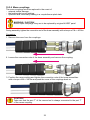
1
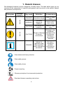
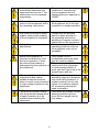
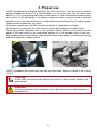
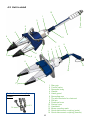
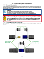
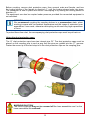
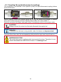
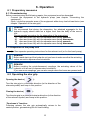
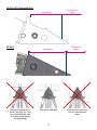
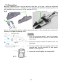
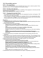
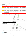
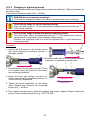
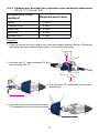
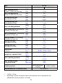
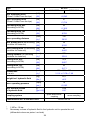
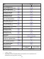
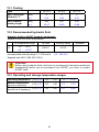
Operating instructions for rescue equipment
Spreaders
271010085 US
Edition 07.2010
replaces 06.2008
(Original operating instructions)
Content
Page
1. Hazard classes
4
2. Product safety
5
3. Proper use
8
4. Description of the functions
9
4.1 Description
9
4.2 Unit in detail
10
4.3 Circuit diagram
11
4.4 Control of the operating movements
11
4.5 Hydraulic supply
11
4.6 Hoses
11
5. Connecting the equipment
12
5.1 General information
12
5.2 Coupling the mono-couplings
12
5.3 Coupling the quick-disconnect-couplings
14
6. Operation
15
6.1 Preparatory measures
15
6.2 Operating the star grip
15
7. Spreading, pulling, peeling and squeezing
16
7.1 Safety notes
16
7.2 Spreading
16
7.3 Pulling
18
7.4 Peeling 18
7.5 Squeezing
19
8. Dismantling the equipment / deactivation following operation
20
8.1 Spreader
20
8.2 Hydraulic unit
20
8.3 Hoses
20
9. Maintenance and service
20
9.1 Spreader, overall
21
9.2 Protective equipment
21
10.Repairs
22
22
10.1 General information
10.2 Preventative service
23
10.3 Repairs
24
11. Troubleshooting
35
2
12. Technical data
37
12.1 Peeling
42
12.2 Recommended hydraulic fluid
42
12.3 Operating and storage temperature ranges
42
13. Notes
43
3
1. Hazard classes
We distinguish between various categories of safety notes. The table below gives you an
overview of the assignment of symbols (pictograms) and key words to the specific hazard
and possible consequences.
Damage /
injury to
device
human
Pictogram
Key word
Definition
Consequences
DANGER!
Immediate danger
Death or major
injury
WARNING!
Potentially
dangerous
situation
Potential death or
major injury
CAUTION!
Less dangerous
situation
Minor or slight
injury
CAUTION!
Danger of damage
to device /
environment
Damage to the
equipment,
damage to the
environment,
damage to
surrounding
materials
REMARK
Advice for
application and
other important /
useful information
and advice
No injury /
damage to
persons /
environment /
equipment
-
Wear helmet with face protection
Wear safety gloves
Wear safety shoes
Proper recycling
Observe principles of environmental protection
Read and observe operating instructions
4
2. Product safety
HURST products are developed and manufactured in order to guarantee the best performance
and quality when used properly.
Operator safety is the most important aspect of the product design.
Moreover, the operating instructions are intended to help the safe use of HURST products.
The generally applicable, legal and other binding regulations pertaining to the prevention of
accidents and protection of the environment apply and are to be implemented in addition to
the operating instructions.
The equipment may only be operated by persons with appropriate training in the safety
aspects of such equipment – otherwise, there is a danger of injury occurring.
We would like to point out to all users that they should read carefully the operating instructions
and the instructions contained therein before they use the equipment, and that they should
carefully follow such.
We further recommend that a qualified trainer train you in the use of the product.
WARNING / CAUTION!
The operating instructions for the hoses, the accessories and the connected
hydraulic equipment must also be observed!
Even if you have already received instructions on how to use the equipment, you should still
read the following safety notes through again.
WARNING / CAUTION!
Ensure that the accessories and connected equipment used are suitable for
the max. operating pressure!
Please ensure that no body
parts or clothing get stuck
between the visibly moving
parts (e.g. spreader arms).
Wear protective clothing, safety
helmet with visor, protective
gloves
It is prohibited to work under
load if this load is lifted
exclusively by hydraulic
equipment. If this work
is absolutely imperative,
additional mechanical supports
must be used.
Inspect the equipment before
and after use for visible defects
or damage
Inspect all cables, hoses
and screwed connections for
leaks and externally visible
damage! If necessary, repair
immediately! Squirting oil can
result in injuries and fires.
The responsible department
is to be informed immediately
of any changes (including to
the operating behaviour)! If
necessary, the equipment is
to be deactivated immediately
and secured!
5
In the event of malfunctions,
immediately deactivate the
equipment and secure it. The
malfunction is to be repaired
immediately.
Do not carry out any changes
(additions or conversions)
to the equipment without
obtaining the prior approval of
HURST.
Observe all safety and danger
notes on the equipment and in
the operating instructions.
All safety and danger notes on
the equipment are to be kept
complete in a legible condition.
Any mode of operation which
impairs safety and/or stability
of the equipment is forbidden!
Comply with all specified
dates or dates specified in
the operating instructions
pertaining to regular controls /
inspections on the equipment.
The maximum permitted
operating pressure noted on
the equipment must not be
exceeded.
Safety devices may never be
deactivated!
Before the equipment is
switched on/started up, and
during its operation, it must
be ensured that nobody is
endangered by the operation of
the equipment.
When working close to live
components and cables,
suitable measures must be
taken to avoid current transfers
or high-voltage transfers to the
equipment.
The build-up of static charge
with the potential consequence
of spark formation is to be
avoided when handling the
equipment.
6
Only original HURST
accessories and spare parts
may be used for repairs.
Please ensure that, when
working with this equipment
or during transportation of
such, you don’t get stuck in the
looped hoses and trip.
Please note that, when
spreading, tearing or breaking
can cause falling material, or
sudden removal of such can
cause it to suddenly catapult
off: necessary precautions
need to be taken.
Only touch any broken-off parts
wearing protective gloves,
since the torn edges can be
very sharp.
The equipment is filled with a
hydraulic fluid. These hydraulic
fluids can be dangerous to
health if swallowed or their
vapours inhaled. Direct contact
with the skin is to be avoided
for the same reason. Please
also note that hydraulic liquids
can also have a negative effect
on biological systems.
When working with or storing
the equipment, ensure that
the function and the safety
of the equipment are not
impaired by the effects of stark
external temperatures or that
the equipment is damaged in
any way. Please note that the
equipment can also heat up
over a long period of use.
Ensure adequate lighting when
you are working.
Before transporting the
equipment, always ensure that
the accessories are positioned
such that they cannot cause an
accident.
Always keep these operating
instructions within reach where
the equipment is used.
Ensure the proper disposal of
all removed parts, left-over oil,
left-over hydraulic fluid and
packaging materials!
The generally applicable, legal and other binding national and international regulations
pertaining to the prevention of accidents and protection of the environment apply and are to
be implemented in addition to the operating instructions.
W A R N I N G
/
C A U T I O N !
The equipment is to be used exclusively for the purpose stated in the operating
instructions (see chapter “Proper Use”). Any other or further use is not considered
proper use. The manufacturer / supplier is not liable for any damages resulting from improper
use. The user bears sole responsibility for such.
Observance of the operating instructions and compliance with the inspection and maintenance
conditions are part of the proper use.
Never work when you are overtired or intoxicated!
7
3. Proper use
HURST spreaders are designed especially for rescue services. They are used to release
persons trapped as a result of a road accident e.g. by forcing open the car doors (see
below Fig. 1) or by squashing other parts of the vehicle. In other catastrophic situations they
are used to lift (by spreading) or to displace objects in order to rescue buried or trapped
persons, e.g. by concrete components in collapsed houses (see below Fig. 2), and to squash
constructional components, e.g. pipes.
In principle, objects can be pulled, spread, squashed or compressed in length.
All objects to be worked on are to be secured using stable supports or substructures.
When lifting loads, additional risks to the operator and/or persons not involved may be
posed if the load moves in an uncontrolled manner or if the spreader slips or tips over.
When applying the tool and lifting, make sure that there is no danger, if necessary by using
additional supports or safety devices.
fig. 1
fig. 2
HURST spreaders and combi tools can also be used under water at a depth of up to 40m
(131 ft).
CAUTION!
In this case, you must strictly observe any leaks in order to avoid threats to the
environment.
CAUTION!
All objects which are to be worked on are to be secured using stable supports or
substructures.
8
WARNING / CAUTION!
The following may not be squeezed:
- live cables
- hardened parts such as springs, spring steels, steering columns and rollers
- explosive bodies such as airbag cartouches
NEVER operate the rescue equipment at a higher operating pressure than that
stated in the chapter “Technical data”. A higher setting can result in material
damage and/or injuries.
HURST rescue equipment may only be used in areas at risk of explosion if an
explosion has been prevented by appropriate measures You must also take into
account that sparks may be created, for example by spreading or squashing an
object.
When working in areas at risk of explosion, all applicable legal,
national and international regulations, standards and safety rules
for avoiding explosions must be observed without limitation!
Spare parts and accessories for the rescue tool can be ordered from your authorisied
HURST-dealer!
4. Description of the functions
4.1 Description
The equipment is designed such that, via a hydraulically activated piston, two equal, opposite
spreader arms are symmetrically opened by mechanical joints, thereby spreading objects.
Closing the spreader arms is also carried out hydraulically and mechanically by reverse
order of the piston.
All spreaders ensure full load-holding function when disconnected from the hydraulic supply
(e. g. when being unintentional decoupled; defective hose, and so on).
(For reasons of safety, equipment SP 510 and SP 512 are internally safeguarded from 63
MPa = 630bar When the safeguarding valve responds a screeching noise can occur. Even
if the screeching noise occurs in unloaded condition, deactivate the equipment immediately
and contact your authorized dealer or HURST directly!)
9
4.2 Unit in detail
10
1
3
5
12
6
9
8
11
2
4
3
6
7
8
2
1
11
9
5
6
12
10
6
7
1
2
3
4
5
6
7
8
9
10
11
12
13
14
Quick-disconnect coupling
system:
14
13
10
Star grip
Control valve
Spreader body
Handle
Hand guard
Spreading arm
Tip with borehole for chain set
Roll pin
Pressure hose
Return hose
Handhold
Mono-coupling male
Quick-disconnect coupling (male)
Quick-disconnect coupling (female)
4.3 Circuit diagram
To enable comprehension of the function, a simplified hydraulic cylinder of the rescue
equipment (A) + hand valve (B) are depicted here.
spreading
A
pulling /
squeezing
B
4.4 Control of the operating movements
The spreading arms movement is controlled via the star grip of the mounted valve.
(see cover, item 1 and, below, figure 3).
fig. 3
star grip
4.5 Hydraulic supply
A HURST motor pump or hand pump only may be used to drive the equipment.
If the pump unit is a different make, you must make sure that it complies with HURST
specifications, otherwise potential dangers may occur which are not the responsibility of
HURST.
Ensure in particular that the authorised operating pressure for HURST equipment is not
exceeded.
REMARK:
Before you use pumps from a different manufacturer, you must contact HURST
or an authorised dealer.
4.6 Hoses
The pump unit and the rescue tool are connected by hoses.
11
5. Connecting the equipment
5.1 General information
There are two short hoses on the side of the equipment: they are connected to the pump unit
via two hoses. All hose assemblies are marked with a colour and have couplings to enable
unmistakable connection.
REMARK:
The devices can be equipped with different coupling systems.
They differ only by the article number and not by the designation.
Of course the coupling systems can also be reequipped at a later time.
WARNING / CAUTION!
Before connecting the equipment you have to pay attention that all
used components are suitable to the max operation pressure of
the pump unit! In the case of doubt you have to inquire HURST
directly!
5.2 Coupling the mono-couplings
The equipment is connected to the hydraulic pump via mono-coupling halves (male and
female).
dust protection caps
mono-coupling
halve (male)
mono-coupling
halve (female)
12
Before coupling, remove dust protection caps, then connect male and female, and turn
the locking sleeve of the female to direction „1“ until the locking sleeve locks into place.
The connection is now in place and secure. Decoupling is by turning the locking sleeve to
direction „0“.
The equipment can also be coupled under pressure provided the connected equipment is
not activated.
REMARK:
We recommend coupling the coupling halves in a pressureless state, when
working in areas with low ambient temperature and the usage of extension hose
assemblies / hose reels, otherwise decoupling could need very high expenditure
of force.
To protect them from dust, the accompanying dust protection caps must be put back on.
Using the dust protection caps:
The “A” dust protection caps have two internal pins “B”. The dust protection caps must be
placed on the coupling pins in such a way that the pins are guided into the “C” grooves.
Fasten the screw up to the limit stop to fix the dust protection caps on the coupling pins.
A
C
B
WARNING/CAUTION!
The mono-couplings may not be screwed off the hose assemblies and / or the
hose assemblies be confused!
13
5.3 Coupling the quick-disconnect-couplings
The equipment is connected to the hydraulic pump via quick-disconnect-coupling halves
(male and female).
X
Y
Before coupling unlock the connect socket by turning the sleeve into position X. Retract
sleeve and connect plug and socket. Release sleeve and turn it into position Y.
Now the connection has been made and locked. Uncoupling is done in the reverse order.
CAUTION!
Always connect the return line first and afterwards the supply line!
REMARK:
Coupling of the devices is only possible, when the hoses are depressurized.
To protect them from dust, the accompanying dust protection caps must be put back on.
WARNING/CAUTION!
The quick-disconnect-couplings partly have special functions. Therefore it is not
allowed to screw them off from the hoses or to exchange them!
14
6. Operation
6.1 Preparatory measures
6.1.1Commissioning
Before commissioning and following repairs, the equipment must be deaerated.
- Connect the equipment to the hydraulic pump (see chapter “Connecting the
equipment”).
- Open / close the spreader arms of the equipment without any load at least twice (see
chapter “Operation of the star grip”).
REMARK:
We recommend that during the deaeration, the attached aggregate for the
hydraulic supply should stand on a higher level than the body of the rescue
tool.
Recommended procedure for the deaeration of the rescue tool:
1.) open and close fully with the spreader arms facing upwards.
2.) open and close fully with the spreader arms facing downwards.
3.) open and close fully with the spreader arms facing upwards.
4.) open and close fully with the spreader arms facing downwards.
6.1.2Inspection of the pump unit
See separate operating instructions for the relevant unit (or for the hand pump).
REMARK:
Before each start-up of the hydraulic unit you have to make sure that the actuating
valves are set to depressurized circulation.
REMARK:
Before coupling the quick-disconnect couplings, the actuating valves of the
hydraulic unit are set to depressurized circulation.
If you use mono-couplings, you can also couple when the hoses are pressurized!
6.2 Operating the star grip
Opening the device (
):
Turn the star grip in a clockwise direction (in the direction of the
relevant symbol) and keep in this position.
Closing the device (
):
Turn the star grip in an counterclockwise direction (in the direction
of the relevant symbol) and keep in this position.
“Dead-man’s” function:
Following release, the star grip automatically returns to the
central position, guaranteeing the full load-holding.
15
7. Spreading, pulling, peeling and squeezing
7.1 Safety notes
Before rescue works can commence, the position of the obstacle must be stabilised. You
must ensure an adequate substructure and / or adequate support of the object. World-wide,
safety guidelines pertaining to the specific country are to be observed and complied with.
In the Federal Republic of Germany, regular safety inspections according to the regulations
of the Gesetzliche Unfallversicherung (GUV; connoted ‘Legal accident insurance’) are
mandatory.
In the event of a potentially explosive situation, it is not permitted to use motor pumps (danger
of the formation of sparks). In such cases, hand pumps are to be used.
The following are to be worn when working with the rescue equipment:
- protective clothing,
- safety helmet with visor or protective goggles,
- protective gloves
- and, if necessary, ear protection
Before activating the rescue equipment, always ensure that there is no danger to persons
either involved / uninvolved in the action by the movement of the rescue equipment or by
flying fragments. Further avoid unnecessary damage to property belonging to others, objects
not involved by the rescue equipment / flying fragments.
Reaching between the spreader arms is strictly forbidden!
WARNING / CAUTION!
The particular effect of the force of the rescue equipment during operation could
cause pieces of the vehicle to break off or fly off, posing a danger to persons.
Those not involved in the rescue operation should therefore keep at a distance
appropriate to the situation.
7.2 Spreading
Use the front area of the tips for increasing the gap only. Full spreading capacity can be
achieved when approximately half of the grooved area of the tips is used. The greatest force
is created in the rear area of the spreading range of the tip.
WARNING / CAUTION!
The arms – made from a light metal alloy – may not be damaged.
16
SP 310, SP 510 and SP 512:
spreading
SP 300:
Working surface is too
small, tips slip off. Only
for increasing the size
of a gap (not suitable
for spreading)
spreading
Tips get a safe grip.
17
Increasing
a gap
Increasing
a gap
Work with the tips only.
Do not damage the
arms.
7.3 Pulling
- HURST chain sets are to be used for pulling purposes.
- Before the pulling process can be performed, ensure that the bolt and hook fit correctly to
prevent the chain from slipping.
- Only chain sets in perfect condition may be used.
- The pull chains are to be inspected at least once per year by an expert.
- See separate operating instructions for the relevant chain set!
Mounting bore for
chain set
SP 310 / SP 510
SP 512
Mounting bore for
chain set
SP 300
7.4 Peeling
With the integrated peeling zone (see figure
below) in the tool tips of spreaders SP 310, SP
510 and SP 512, sheet steels can be peeled
open (for maximum sheet steel thickness t, see
chapter “Technical data”).
Peeling zone
WARNING / CAUTION!
Splinters can fly uncontrollably from particularly hard materials.
Keep a safe distance!
18
7.5 Squeezing
Basically, squeezing may only be carried in the area of the tips, unless an additional
squeezing device is used – see figures 6 and 7 below. (This additional squeezing device is
only available as an accessory for the spreader SP 310).
fig. 6
fig. 7
A
Squeezing plates A
B
C
Use of this squeezing device enables squeezing closer to the spreader arm pivot point,
resulting in a higher squeezing force.
Spreader arm
Assembly:
1. Push the squeezing plate A over the spreader
arm until boreholes B1 and B2 lie flush above
each other.
B1
B2
2. Position the spacer washer C between the two
boreholes..
fig. 8
A
3. Put the screw B from the opposite side of the
spreader arm through borehole B1 and spacer
washer C (see figure 9).
C
B
fig. 9
4. Screw the screw B tightly into borehole B2.
A
19
8. Dismantling the equipment / deactivation following
operation
8.1 Spreader
Once work has been completed, the spreader arms are to be closed so that there is a
tip distance of just a few mm. This relieves the hydraulic and mechanical strain on the
equipment.
8.2 Hydraulic unit
Upon completion of work, the unit must be deactivated.
8.3 Hoses
First of all, decouple the pressure hose then the return hose as described in chapter
“Connecting the equipment”. Ensure that you put the dust protection caps back on to the
couplings.
9. Maintenance and service
The equipment is subject to very high mechanical stresses. A visual inspection is to be
carried out after every use: however, at least one visual inspection is to be carried out
annually. These inspections enable the early detection of wear and tear, which means that
punctual replacement of this wearing parts prevents breakages from occurring. A function
test is also to be carried out every three years or should there be any doubt regarding the
safety or reliability of the equipment.
(Please also observe the relevant valid national and international regulations pertaining to
service intervals of rescue equipment). In the Federal Republic of Germany, regular safety
inspections according to the regulations of the Gesetzlichen Unfallversicherung (GUV;
connoted ‘Legal accident insurance’) are mandatory.
CAUTION!
Clean off any dirt before controlling the equipment!
WARNING / CAUTION!
In order to carry out maintenance and repair works, tools appropriate for the job
and personal protecting equipment are essential.
20
9.1 Spreader, overall
Inspections to be carried out:
Visual inspection
Spreader
• Opening width of the spreader arms on the tips (see chapter “Technical data”),
• General tightness (leaks),
• Operability of the star grip,
• Existence and stability of handle,
• Labels completely existent and legibly,
• Covers in perfect condition,
• Couplings must be easy to couple,
• Dust protection caps must be available.
Spreader arms
• Spreader arms free of tears and without any chipped spots or deformations on the surfaces,
• Bolts and retaining rings of the spreader arms must be present and in correct working order,
• Grooving of the tips must be clean and squared, and not have any tears
• Tips existent and locked (for SP 300)
Hoses (see also operating instructions for hydraulic hoses)
• Visual control for visible damage,
• Control for leaks.
Function test
• Opening and closing function flawlessly upon activation of the star grip,
• no suspicious noises.
• no further movement of the spreader arms upon interruption of the valve activation during
the process (“dead-man’s” function)
9.2 Protective equipment
• Control of the protective equipment on / around the rescue equipment, especially the
hand guard of the moveable parts (they must be free of tears!).
21
10.1 General information
10. Repairs
Servicing may only be carried out by the manufacturer or personnel trained by the
manufacturer and by authorised HURST dealers.
Only HURST spare parts may be used to replace all components (see spare parts list) since
special tools, assembly advice, safety aspects, inspections might have to complied with (see
also chapter “Maintenance and Service”).
During assembly, ensure the complete cleanliness of all components, since dirt can
damage the rescue equipment!
WARNING / CAUTION!
Protective clothes must be worn when repairs are being carried out, since parts
of the units can also be pressurised in an idle state.
REMARK:
Please always return the guarantee registration card to HALE PRODUCTS,
INC. or register your tool on the HURST website. Only then are you entitled to
the extended guarantee.
REMARK:
Before you use couplings from a different company, you must contact HURST
or an authorised dealer.
REMARK when using the quick-disconnect-coupling system:
Overpressure protection of the rescue equipment
(model with yellow coupling nipple on the return hose)
If the equipment’s short hoses are not connected to a unit, temperature
increases can inadvertently cause pressure to build up in the equipment. Hence,
the return hose of the equipment is equipped with a safety coupling (quickdisconnect coupling male, yellow). Unwanted overpressure (approx. 1.5 Mpa) is
automatically released via this nipple: hydraulic fluid leaks.
Should an hydraulic fluid leak on the coupling male be more frequent, please
contact your dealer or HURST itself.
If couplings from a different company are used which do not have this function,
the overpressure protection can react in the valve of the rescue equipment.
Hydraulic fluid leaks in the area of the star grip. Following the reduction in
pressure, the valve is once again tight.
Should the valve leak permanently, please immediately contact your dealer or
HURST itself.
CAUTION!
Because HURST rescue equipments are appropriate for highest achievements,
only components may be exchanged, which are specified in the spare parts list
of the appropriate equipment.
Further components of the equipment may only be exchanged, when:
- you have participated on a appropriate HURST service training.
- you have the explicit permission of the HURST Service department (After
inquiry, an examination for the distribution of permission is being carried out. An
examination in each individual case is necessary!)
22
10.2 Preventative service
10.2.1 Care regulations
The exterior of the equipment is to be cleaned from time to time in order to protect it from
external corrosion. Oil is to be applied to the metallic surfaces.
10.2.2 Function and load test
If there is any doubt regarding the safety or reliability of the equipment, a function and load
test must also be performed.
HURST offers appropriate test equipment to this end.
10.2.3 Changing the hydraulic fluid
- The hydraulic fluid must be changed after the equipment has been used approx. 200
times / after three years at the latest.
- It must always be changed whenever the hydraulic fluid for the accompanying pump
(motor / hand pump) is changed. This is to prevent the fresh hydraulic fluid from becoming
contaminated by the used fluid from the rescue equipment.
Procedure:
1. Close spreader arms (until the tips are almost touching).
2. Change the hydraulic fluid of the pump. Please observe the separate operating instructions
for the pump being used!
3. Screw off the return hose on the pump:
- when the hose connection is directly into the pump:
completely unscrew the connection nut of the connection piece of the blue return hose.
- when the hose connection is via mono-coupling to the pump:
remove the cover from the mono-coupling (male).
completely unscrew the connection nut of the blue returnhose on the mono-coupling (male).
- when the hose connection is via quick-connect-coupling to the pump:
completely unscrew the connection nut on the quick-disconnect-coupling of the blue
return hose.
4. Put the return hose into a separate collecting basin for the hydraulic fluid still in the equipment.
5.Slowly open the tool (the pump must be working during this time). The old hydraulic fluid
from the piston space side runs via the return hose into the separate collecting basin, and
is to be disposed of in the same manner as the old hydraulic fluid of the pump.
6.Switch the pump off (motor pump) / no longer activate it (e.g. hand pump).
7.Reconnect the return hose to the pump:
- when the hose connection is directly into the pump:
screw the connection nut of the connection piece of the blue return hose back on.
(Please observe the necessary torque of MA = 40 Nm!)
- when the hose connection is via mono-coupling to the pump:
screw the connection nut of the blue return hose back onto the mono-coupling (male).
(Please observe the necessary torque of MA = 40 Nm!)
Pull back the cover on the couplings as far as the limit stop.
- when the hose connection is via quick-connect-coupling to the pump:
screw the connection nut back onto the quick-disconnect-coupling of the blue return hose.
(Please observe the necessary torque of MA = 35 Nm!)
8.Deaerate the rescue tool as described in the chapter “Preparatory measures”.
23
10.3 Repairs
10.3.1 Chaging the tip (SP 310, SP 510 and SP 512)
Procedure:
1. Use the pulling pin to remove the roll pin “A”,
2. Replace tip,
CAUTION!
Before assembly, apply HURST special grease to all sliding surfaces after
having thoroughly cleaned them.
3. Hammer in new roll pin.
CAUTION!
Before assembly, apply HURST special grease to all sliding surfaces after
having thoroughly cleaned them.
Also observe the installation position of the adapter sleeve to ensure optimum
force distribution!
Installation position of the roll pin of the SP 310 and SP 510:
The opening of the roll pin should face towards the
A
squeezing surfaces (see figure, right)
Installation position of the spiral pin of the SP 512:
The external start of the spiral pin should
face towards the rear end of the tip
(see figure, right)
A
The roll pin / spiral pin comes with the tip. Pressing onto the tips on the spreader arm enables
the roll pins to be inserted more easily into the boreholes.
REMARK:
Always replace both tips.
24
10.3.2 Replacing the plug-on tips (SP 300)
Procedure:
1. In order to remove the plug-on tips “G”, you need to push the buttons “J” on both sides of
a spreader arm completely and simultaneously and then remove the plug-on tip from the
spreader arm by pulling it forwards.
2. Place the new tips onto the arm until they automatically click in place on the spreader
arm.
J
H
H
J
G
G
NOTE:
Always replace both plug-on tips.
When inserting the new tips, push both buttons “J” until the tip can be slid over
them.
After fitting, make sure that both buttons “J” are locked on each arm (that they
are back in their original position).
25
10.3.3 Changing or tightening hoses
Hoses of the pressure and/or return pipe leaks or hoses are defective. Tighten the hoses on
the safety valve.
(Please note! Observe torque of MA = 40 Nm!)
REMARK when using mono-couplings:
If you want to change the hoses, you have to dismantle the mono-couplings.
CAUTION (by usage of mono-coupling-system)!
Take care that the port ‘T’ of the rescue tool is always connected to the port ‘T’
of the mono-coupling.
CAUTION (by usage of quick-disconnect-coupling-system)!
The return hose, which is screwed onto the port “T” of the rescue tool, must be
equipped with a quick-disconnect-coupling (male) always.
However the supplying hose line must be equipped with a quick-disconnectcoupling (female).
Procedure:
C
B
1. Loosen the 2 B screws in the handle sleeve
with quick-disconnect protective sleeves C
(hexagon socket)
A
2. Remove handle sleeve A and tighten screwed
connection. If necessary, renew seals.
F
E
D
3. Dismantle hose D and sealing ring E. (There
is no need to carry out this point if the hoses
are just being tightened).
4. Screw the hose with sealing ring back on.
Please ensure that the insulating washer F is
on and correctly assembled.
5. Tighten the hose connection on the safety
valve. (Please note! Observe the necessary
torque of MA = 40 Nm!)
dismantle
assemble
6. Then replace handle sleeve, protective sleeves and screws, tighten (Torque: 5Nm) and
secure it with threadlocking fluid (e. g. LOCTITE 243).
26
10.3.4 Spreader arm, spreader tips, protection cover and handle replacement
(SP 310, SP 510 and SP 512)
Components to be
replaced
Required work steps
Handle
1. - 3. and 7.
Protective cover
1. - 4. and 7.
Plug-on tips
1. - 5. and 7.
Lever links
1. - 5. and 7.
Spreader arms
1. - 6. and 7.
Procedure:
1. Close the rescue unit until a gap of only a few mm remains between the tips. Disconnect
the device from the hydraulic power supply unit and clean thoroughly.
C
B
2. Unscrew nuts “A”, remove washers “B” and
remove fixing bolts “C”.
B
B
D
A
3. Pull the handle “D” backwards over the hose
connections.
F
4. In the same way, pull the protective cover
“E” backwards over the hose connections.
27
E
J
H
J
F
5. Drive the pins “F” out with a drift and remove
the plug-on tips “G”. Remove the locking
rings “H” and remove the handlebars “J”.
J
G
H
L
K
L
6. The pins “L” can be removed after removing
the locking rings “K”. You can now remove
the spreader arms “M” and replace them.
M
K
M
7. The work steps must be carried out in reverse order to fit the new parts.
CAUTION!
Don’t forget to apply HURST special grease to all sliding surfaces.
NOTE:
The torque required can be taken from the spare parts list of your particular
unit.
28
10.3.5 Spreader arm, spreader tips, protective cover and handle replacement
on the SP 300 spreader
Components to be
replaced
Required work steps
Handle
1., 2. and 8.
Protective cover
1., 5. and 8.
Plug-on tips
1. - 4. and 8.
Lever links
1. - 4., 6. and 8.
Spreader arms
1. - 6. and 8.
Work steps:
1. Close the rescue unit until a gap of only a few mm remains between the tips. Disconnect
it from the hydraulic power supply unit and clean thoroughly.
A
2. Remove the fixing screws “A” and
remove the handle “B”.
B
29
C
C
3. Remove the screws “C“ and “D”.
D
C
E
C
4. Remove the two two-piece locking
elements “E” on the protective cover “F”
and remove the two-piece protective
cover by pulling it sideways.
F
F
30
5. In order to remove the plug-on tips
“G”, you need to push the buttons
“J” on both sides of a spreader arm
completely and simultaneously and
then remove the plug-on tip from the
spreader arm to the front.
H
J
H
J
G
G
6. You need to remove the locking rings “K” and the lever links “L” to replace the spreader
arms “H”.
K
L
K
L
H
L
K
L
K
K
31
7. Also remove the locking rings “M” and remove the pins “N”. You can then remove the
spreader arms “H”.
H
M
N
H
M
8. The work steps must be carried out in reverse order to fit the new parts.
CAUTION!
Don’t forget to apply HURST special grease to all sliding surfaces.
NOTE:
The torque required can be taken from the spare parts list of your particular
unit.
32
10.3.6 Mono-couplings
The mono-couplings must be replaced in the event of:
- external visible damage,
- the locking device not working,
- hydraulic fluid continually leaking in a coupled/uncoupled state.
WARNING / CAUTION!
Never repair couplings: they are to be replaced by original HURST parts!
During assembly, tighten the connection nut of the hose assembly with a torque of MA = 40 Nm.
Procedure:
1. Remove the cover from the couplings.
2. Loosen the connection nuts of the hose assembly and remove the coupling.
3. Position the new coupling and tighten the connection nuts of the hose assemblies with a torque of MA = 40 Nm and push the cover of the couplings back on.
CAUTION!
Take care that the port ‘T’ of the rescue tool is always connected to the port ‘T’
of the mono-coupling.
33
10.3.7 Quick-disconnect-couplings
The quick-disconnect-couplings must be replaced in the event of:
- external visible damage,
- the locking device not working,
- hydraulic fluid continually leaking in a coupled/uncoupled state.
WARNING / CAUTION!
Never repair couplings: they are to be replaced by original HURST parts!
During assembly, tighten the connection nut of the hose assembly with a torque of MA = 35 Nm.
Procedure:
1. Loosen the connection nut of the hose assembly and remove the coupling.
2. Position the new coupling and tighten the connection nut of the hose assemblies with a torque of MA = 35 Nm.
CAUTION!
The return hose, which is screwed onto the port “T” of the rescue tool, must be
equipped with a quick-disconnect-coupling (male) always.
However the supplying hose line must be equipped with a quick-disconnectcoupling (female).
10.3.78Valve cover
If the cover is deformed to such an extent that the star grip no long works correctly, the valve
must be replaced in its entirety.
Have repairs carried out by an authorised dealer, by personnel specially trained by HURST,
or by HURST customer service only.
10.3.9 Labels
All damaged and/or illegible labels (safety notices, type plate, etc.) must be renewed.
Procedure:
1. Remove damaged and/or illegible labels.
2. Clean the surfaces using industrial alcohol.
3. Attach new labels.
Ensure that you attach the labels in the right position. If you are no longer sure about this,
then please contact your authorised HURST dealer or HURST itself.
34
11. Troubleshooting
Trouble
Control
Spreader arms move Are the hoses
slowly or jerkily when connected
activated
properly?
Does the pump
unit work?
Device doesn’t
Check the
perform at its given
hydraulic fluid level
power
in the supplying
pump
Following release,
Cover damaged
the star grip doesn’t
or star grip hard to
return to the central
move?
position
Cause
Solution
Air in the hydraulic Deaerate pump
system
system
Insufficient
hydraulic fluid in
the pump
Top up hydraulic fluid,
deaerate
Damage to the
torsion spring for
reset
Soiled valve or
star grip
Repair by an
authorised dealer, by
personnel specially
trained by HURST, or
by HURST itself
Defective valve
Other mechanical
damage (e. g. star
grip)
Pressure too high
(e.g. caused by
too-high ambient
temperature)
Coupling defective
with mono-couplingsystem: Hoses
cannot be coupled
with monocoupling-system:
It is frequently not
possible to couple
hose assemblies
Set hydraulic pump
to pressureless
circulation
Coupling needs to be
replaced immediately
Hydraulic fluid
Hydraulic fluid
Control the
must be replaced
degree of viscosity not adapted to
the application
(see chapter
and application
situation
“Recommended
temperature of
Hydraulic fluids”)
the used hydraulic
fluid
Coupling defective Coupling needs to be
replaced immediately
with quickdisconnect-couplingsystem: Hoses
cannot be coupled
Is the pump
working?
Pressurized
Relieve pump
Coupling defective Coupling needs to be
replaced immediately
Hydraulic fluid leak
on the hoses or the
fixing-ins
Are the hoses
defective?
Leak, possible
damage
35
Replace hoses
Trouble
Damages on the
surface of the
hydraulic hoses
Control
Cause
Mechanical
damages or
contact with
aggressive agents
Defective rod seal
Damage to the
piston
Hydraulic fluid leaks
on the piston rod
Solution
Replace hoses
Repair by an
authorised dealer, by
personnel specially
trained by HURST, or
by HURST itself
Secure the loads and
Leak on the handhold Increase load?
Load increase
move them by using
(e.g. something
has fallen onto the other tools
part to be lifted,
Move the load
thereby suddenly somewhere else,
increasing the
where the moving
load)
load is lighter
Use supporting
equipment to move
the load.
Does the pressure Pressure release Following the
in the Rescue tool. reduction in pressure,
set on the pump
no further leak is
comply with
present.
the maximum
permissible
Should, however,
pressure on
there be a further
the rescue
leak on the handhold,
equipment?
immediately
deactivate the rescue
equipment, and
contact an authorised
dealer or HURST
itself.
Hoses in handhold Hoses in handhold Tighten hoses.
loose?
not tightened
Supply and return Reconnect the
Check the
connections of the connection of the hoses of the monocooupling (female) in
mono-coupling
mono-coupling
(female) inverted the right way
(female)
Especially by usage
of quick-disconnectcouplings: Leak on
the handhold
Is the return
hose connected
correctly?
Return hose is not Re-connect the return
coupled correctly hose and secure it.
or not connected.
36
Trouble
Control
Cause
Especially by usage check the
hose connection
of mono-couplings:
connections of the to the couplings
Leak on the handhold hoses
interchanged
Returnline
disabled
Solution
reconnect the hoses
to the coupling in the
right way
disconnect the
returnline from the
coupling, clean it and
reconnect it.
with mono-couplingsystem: Leak in the
couplings
Is the coupling
damaged?
coupling damaged Coupling must be
replaced immediately
with quickdisconnect-couplingsystem: Leak in the
couplings
Is the coupling
damaged?
coupling damaged Coupling must be
replaced immediately
Is the leak only on Safety valve
the coupling male? reacted
After pressure
release there is no
more leakage.
If it isn’t possible to rectify the malfunctions, inform an authorised HURST dealer or the
HURST customer service department immediately!
The address for the HURST customer service department is:
HURST
JAWS OF LIFE
HALE PRODUCTS, INC.
A Unit of IDEX Corporation
711 N. Post Road
Shelby, NC 28150 USA
Phone: (704) 487-6961
Fax:
(704) 487-7271
e-mail: [email protected]
12. Technical data
Since all values are subject to tolerances, minor differences may occur between the data on
your equipment and the data in the following schedules!
NOTE:
The following tables contain only the technical data required for standard
acceptance.
Additional data concerning your unit can be obtained from HURST on request.
37
type
SP 300
ref. no.
211051000
271051000
min. spreading force
(25mm / 0.98in. from the tips)
[kN]
34
[lbf.]
7,644
max. spreading force
(25mm / 0.98in. from the tips)
[kN]
42
[lbf.]
9,442
spreading force HSF
(according to NFPA)
[kN]
40
[lbf.]
8,993
spreading force LSF
(according to NFPA)
[kN]
33
[lbf.]
7,419
[mm]
605
max. spreading distance
[in.]
23.82
min. pulling force (on mounting
borehole for chain set)
[kN]
22,5
[lbf.]
5,058
max. pulling force (on mounting
borehole for chain set)
[kN]
28
[lbf.]
6,294
pulling distance (on mounting
borehole for chain set)
[mm]
495
[in.]
19.49
pulling force HPF
(according to NFPA)
[kN]
23
[lbf.]
5,171
pulling force LPF
(according to NFPA)
[kN]
19
[lbf.]
4,272
dimensions
lxwxh
weight incl. hydraulic fluid
max. operating pressure
min. needed volume
of hydraulic fluid
[mm]
750 x 355 x 255
[in.]
29.53 x 13.98 x 10.04
[kg]
17,1
[lbs.]
37.7
[Mpa] *
70
[psi.]
10,153
[l] **
0,14
[gal.-US]
0.04
quick-disconnect
coupling
coupling system
classification acc. to DIN EN 13204
*
**
mono-coupling
AS 34/605-17
1 MPa = 10 bar
Necessary volume of hydraulic fluid in the hydraulic unit to operate the unit (differential volume on piston / rod side)
38
type
SP 310
ref. no.
min. spreading force
(25mm / 0.98in. from the tips)
211010000
271010000
[kN]
46
[lbf.]
10,342
max. spreading force
(25mm / 0.98in. from the tips)
[kN]
61
[lbf.]
13,714
spreading force HSF
(according to NFPA)
[kN]
53
[lbf.]
11,915
[kN]
39
[lbf.]
8,768
[mm]
720
spreading force LSF
(according to NFPA)
max. spreading distance
[in.]
28.35
min. pulling force (on mounting [kN]
borehole for chain set)
[lbf.]
30
6,745
max. pulling force (on mounting [kN]
borehole for chain set)
[lbf.]
42
9,442
pulling distance (on mounting
borehole for chain set)
[mm]
[in.]
22.64
pulling force HPF
(according to NFPA)
[kN]
30,5
[lbf.]
6,857
pulling force LPF
(according to NFPA)
[kN]
23
[lbf.]
5,171
dimensions
lxwxh
[mm]
weight incl. hydraulic fluid
max. operating pressure
min. needed volume
of hydraulic fluid
575
790 x 350 x 190
[in.]
31.10 x 13.78 x 7.48
[kg]
20,1
[lbs.]
44.3
[Mpa] *
70
[psi.]
10,153
[l] **
0,24
[gal.-US]
0.07
quick-disconnectcoupling
coupling system
classification acc. to DIN EN 13204
*
**
mono-coupling
AS 46/720-20
1 MPa = 10 bar
Necessary volume of hydraulic fluid in the hydraulic unit to operate the unit (differential volume on piston / rod side)
39
type
SP 510
ref. no.
211030000
271030000
min. spreading force
(25mm / 0.98in. from the tips)
[kN]
62
[lbf.]
13,938
max. spreading force
(25mm / 0.98in. from the tips)
[kN]
92
[lbf.]
20,683
spreading force HSF
(according to NFPA)
[kN]
79,9
[lbf.]
17,963
spreading force LSF
(according to NFPA)
[kN]
54,6
[lbf.]
12,275
[mm]
800
max. spreading distance
[in.]
31.50
min. pulling force (on mounting [kN]
borehole for chain set)
[lbf.]
38
8,543
max. pulling force (on mounting [kN]
borehole for chain set)
[lbf.]
55
12,365
pulling distance (on mounting
borehole for chain set)
[mm]
[in.]
26.18
pulling force HPF
(according to NFPA)
[kN]
44,4
[lbf.]
9,982
pulling force LPF
(according to NFPA)
[kN]
31,1
[lbf.]
6,992
dimensions
lxwxh
[mm]
weight incl. hydraulic fluid
max. operating pressure
min. needed volume
of hydraulic fluid
665
900 x 380 x 215
[in.]
35.43 x 14.96 x 8.46
[kg]
25,5
[lbs.]
56.2
[Mpa] *
70
[psi.]
10,153
[l] **
0,43
[gal.-US]
0.12
quick-disconnectcoupling
coupling system
classification acc. to DIN EN 13204
*
**
mono-coupling
BS 62/800-25
1 MPa = 10 bar
Necessary volume of hydraulic fluid in the hydraulic unit to operate the unit (differential volume on piston / rod side)
40
type
SP 512
ref. no.
211040000
271040000
min. spreading force
(25mm / 0.98in. from the tips)
[kN]
84
[lbf.]
18,885
max. spreading force
(25mm / 0.98in. from the tips)
[kN]
120
[lbf.]
26,978
spreading force HSF
(according to NFPA)
[kN]
108
[lbf.]
24,278
spreading force LSF
(according to NFPA)
[kN]
77
[lbf.]
17,311
[mm]
610
max. spreading distance
[in.]
24.02
min. pulling force (on mounting [kN]
borehole for chain set)
[lbf.]
66
14,838
max. pulling force (on mounting [kN]
borehole for chain set)
[lbf.]
99
22,257
pulling distance (on mounting
borehole for chain set)
[mm]
[in.]
17.20
pulling force HPF
(according to NFPA)
[kN]
67
[lbf.]
15,063
pulling force LPF
(according to NFPA)
[kN]
49
[lbf.]
11,017
dimensions
lxwxh
[mm]
weight incl. hydraulic fluid
max. operating pressure
min. needed volume
of hydraulic fluid
437
795 x 380 x 216
[in.]
31.30 x 14.96 x 8.50
[kg]
26,4
[lbs.]
58.2
[Mpa] *
70
[psi.]
10,153
[l] **
0,34
[gal.-US]
0.09
quick-disconnectcoupling
coupling system
classification acc. to DIN EN 13204
*
**
mono-coupling
CS 84/610-26
1 MPa = 10 bar
Necessary volume of hydraulic fluid in the hydraulic unit to operate the unit (differential volume on piston / rod side)
41
12.1 Peeling
Type
SP 310
[mm]
SP 510
SP 512
4
5
5
0.16
0.20
0.20
max. sheet steel
thickness “t”
[in.]
max. possible
peeling length
[mm]
520
650
500
[in..]
20.47
25.59
19.69
12.2 Recommended hydraulic fluid
Hydraulic fluid for HURST hydraulic equipment:
Mineral oil DIN ISO 6743-4 and others
Oil temperature range
A
-20 .... +55°C
-4.0 .... +131°F
Oil code
Viscosity rating
HM 10
VG 10
recommended viscosity range: 10...200 mm²/s
Supplied with HM 10 DIN ISO 6743-4.
Remarks
(10…200 cSt.)
CAUTION!
Before using hydraulic fluids, which do not correspond to the above-mentioned
specifications and/or are not purchased from HURST, you have to contact
HURST itself!
12.3 Operating and storage temperature ranges
Operating temperature
Ambient temperature
(device in operation)
Storage temperature
(device not in operation)
[°C] / [°F]
-20 … +55
-4 …
+131
[°C] / [°F]
-25 … +45
-13 …
+113
[°C] / [°F]
-30 … +60
-22 …
+140
42
13. Notes
43
Please dispose all packaging materials and
dismantled parts properly
HURST
JAWS OF LIFE
HALE PRODUCTS, INC.
A Unit of IDEX Corporation
Phone: (704) 487-6961
Fax:
(704) 487-7271
e-mail: [email protected]
Made in GERMANY
Spreader_BA_US_271010085_0710.indd
© Copyright 2010 HALE PRODUCTS, INC.
subject to revision
711 N. Post Road
Shelby, NC 28150 USA