1
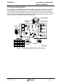
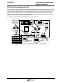
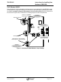
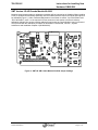
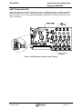
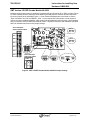
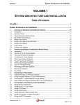
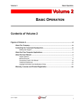
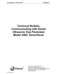
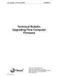
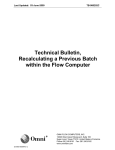
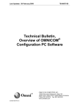
Last Updated: 21-July-2010
TB-070216C
Technical Bulletin,
Instructions for Installing
New Hardware
OMNI 6000
OMNI FLOW COMPUTERS, INC.
12620 West Airport Boulevard, Suite 100
Sugar Land, Texas 77478 United States of America
Phone-281.240.6161 Fax: 281.240.6162
www.omniflow.com
52-0001-0007/Rev C
Page 1 of 13
TB-070216C
Instructions for Installing New
Hardware OMNI 6000
Table of Contents
Scope ............................................................................................................................................3
Abstract .........................................................................................................................................3
I/O A/B Combo Module 68-6006 ...................................................................................................4
I/O E/D and E Combo Module 68-6008.........................................................................................5
SV I/O Module 68-6203.................................................................................................................6
SMT Version I/O A/B Combo Module 68-6206 .............................................................................7
HART I/O Module 68-6207............................................................................................................8
SMT Version I/O E/ED Combo Module 68-6208...........................................................................9
SE Ethernet Module 68-6209 ......................................................................................................10
Digital I/O Module 68-6211..........................................................................................................11
Universal Power Supply Module 68-6218 ...................................................................................12
Figures
Figure 1.
Figure 2.
Figure 3.
Figure 4.
Figure 5.
Figure 6.
Figure 7.
Figure 8.
Figure 9.
I/O A/B Combo Module 68-6006 Jumper Settings ........................................................4
I/O E/D and E Combo Module 68-6008 Jumper Settings .............................................5
SV I/O Module 68-6203 Module Jumper Settings.........................................................6
SMT I/O A/B Combo Module 68-6206 Jumper Settings ...............................................7
HART I/O Module 68-6207 Jumper Settings.................................................................8
SMT I/O E/ED Combo Module 68-6208 Jumper Settings.............................................9
SE Ethernet Module 68-6209 Module Jumper Settings ..............................................10
Digital I/O Module 68-6211 Module Jumper Settings..................................................11
Universal Power Supply Module 68-6218 ...................................................................12
52-0001-0007/Rev C Page 2 of 13
TB-070216C
Instructions for Installing New
Hardware OMNI 6000
Scope
Users are requested to verify the jumper settings on modules before installing into a current system. This
will prevent miss match I/O address and possible computer systems resetting because of address
conflicts. Particular attention is required when installing an SV module into an existing system that does
not contain an SV module per Figure 3 (Applications 23/27 and 21/25 only).
This Technical Bulletin is applicable to all spare part modules. The information is targeted to qualified
professionals only and compliments the OMNI User Manual Volume 1, System Architecture and
Installation (50-0000-0001) for detailed instructions.
NOTE: SMT is Surface Mount Technology which is the manufacturing method on circuit board assembly. Abstract
This Technical Bulletin contains information on the I/O modules and the standard factory jumper settings
on these modules when they are purchased as spare parts to add to existing system or to replace a
damaged module.
WARNING: DANGER ELECTRICAL SHOCK HAZARD
Dangerous AC voltages are present on the power supply module and ribbon cable when the
unit is AC powered. To avoid electrical shock, that could be fatal; it is imperative that you
remove all power before opening and disassembling the flow computer and take all
necessary precautions.
Only qualified Technicians should work on internal circuitry and perform flow computer
upgrades. OMNI Flow Computers, Inc. is not responsible for personal injuries or accidents
that may occur when working on flow computer circuitry.
Static electricity can damage flow computer circuitry. Use approved static device handling
precautions.
When removing the CPU Module, take extreme care not to bend or fold the keypad
membrane ribbon cable, as this could damage the metallic traces.
Before installing your new or repaired module you will need to verify certain jumper settings for the
module you are using. This is due to the fact that these modules have a selectable type address.
Normally this is preset at the factory; however it is up to the user to verify/change the address simply by
selecting the correct type of card and address on the selection jumpers located on the module. Failure
to do so, will cause the unit not to recognize the newly installed module, lose existing data, or in some
cases a system failure. Within this document we have addressed the various jumper settings required to
properly install the module.
52-0001-0007/Rev C Page 3 of 13
TB-070216C
Instructions for Installing New
Hardware OMNI 6000
I/O A/B Combo Module 68-6006
When installing a new or repaired Combo Module (68-6006) note that the modules will also require the
inputs and outputs to be calibrated (Figure 1). Under ‘Password Maintenance’ scroll down to entries,
”Input Cal Default” and “D/A Cali Default”, enter Y or the required I/O Point number on both entries to
reset to the factory calibration defaults. New combo modules added will require that the ‘Check Modules’
entry is executed. Then proceed with the calibration procedure as described in User Manual, Volume 1,
System Architecture and Installation Chapter 8 (50-0000-0001).
JP11
Select ‘P’
(Pulse Type
Input - Channel
3 or 4)
Chan 4 Threshold
JP11 In = 3.5 VDC
4-20mA Jumper Out
(Pulse Type Input)
JP11
Select Module Type
JPB Out = A Type
Address Select
(Address #2 Shown)
Module
A0
A1
A2
#1
Out Out Out
#2
In
Out Out
#3
Out
In
Out
#4
In
In
Out
#5
Out Out
In
#6
In
Out
In
JP12
RTD2
D/A2
JP12 In D/A2
Position
JP13 In DC
Coupled Position
Figure 1. I/O A/B Combo Module 68-6006 Jumper Settings
52-0001-0007/Rev C Page 4 of 13
TB-070216C
Instructions for Installing New
Hardware OMNI 6000
I/O E/D and E Combo Module 68-6008
When installing a new or repaired Combo Module (68-6008) note the modules will also require the inputs
and outputs to be calibrated (Figure 2). Under ‘Password Maintenance’ scroll down to entries, ”Input Cal
Default” and “D/A Cali Default”, enter Y or the required I/O Point number on both entries to reset to the
factory calibration defaults. New combo modules added will require that the ‘Check Modules’ entry is
executed. Then proceed with the calibration procedure as described in User Manual, Volume 1, System
Architecture and Installation Chapter 8 (50-0000-0001).
For I/O E/D and E Combo Modules 68-6008 settings refer to Figure 2.
Input Threshold Select
JP8&JP1 In = +3.5 Volt
DC Out=1.2Volt DC
JP3
JP8 THRES
JP4
JP3
Select Module Type
JPD In = E/D Module
RTD 4-20
INPUT 1
JP4
RTD 4-20
INPUT 1
RTD
Selected
JP5
JP8 THRES
JP1 THRES
JP2
JP7
AC DC AC
INPUT 4
AC DC AC
INPUT 3
Address Select
(Address #2 Shown)
Module
#1
#2
#3
#4
#5
#6
A0
Out
In
Out
In
Out
In
A1
Out
Out
In
In
Out
Out
JP5
A2
Out
Out
Out
Out
In
In
JP2
JP7
AC DC AC
INPUT 4
AC Coupling
Select
AC DC AC
INPUT 3
JP6
RTD 4-20
INPUT 2
JP6
RTD 4-20
INPUT 2
DC Coupling
Select
4-20 mA
Selected
Figure 2. I/O E/D and E Combo Module 68-6008 Jumper Settings
52-0001-0007/Rev C Page 5 of 13
TB-070216C
Instructions for Installing New
Hardware OMNI 6000
SV I/O Module 68-6203
Spare SV 68-6203 modules ordered from the factory are set up as address SV1 with BRD SEL jumper
in, and IRQ set to 2. If you are installing a SV module into a new system where existing serial modules
are installed, you MUST change the IRQ setting on all serial cards to IRQ 3 (Figure 3). Failure to do
this will cause a system failure. Calibration on all analog outputs will need to be performed.
st
Jumper In = 1 SV Module
nd
Jumper Out = 2 SV Module
SV Address
Selection Jumpers
IRQ 2 Always Selected
LED Indicators
PORT 1 (3)
PORT 2 (4)
RTS Always Selected
Transmitting (TX)/Ready-toSend (RTS) LEDs Red
Receiving LEDs Green
Both Jumpers In = Port Terminated
Both Jumpers Out = Port Unterminated
SV RS-485
Termination Jumpers
Figure 3. SV I/O Module 68-6203 Module Jumper Settings
52-0001-0007/Rev C Page 6 of 13
TB-070216C
Instructions for Installing New
Hardware OMNI 6000
SMT Version I/O A/B Combo Module 68-6206
Modules issued as spare parts or replacement modules will be jumpered as A1 Modules When installing
a new or repaired Combo Module (68-6206) note the modules will also require the inputs and outputs to
be calibrated (Figure 1). Under ‘Password Maintenance’ scroll down to entries, ”Input Cal Default” and
“D/A Cali Default”, enter Y or the required I/O Point number on both entries to reset to the factory
calibration defaults. New combo modules added will require that the ‘Check Modules’ entry is executed.
Then proceed with the calibration procedure as described in User Manual, Volume 1, System
Architecture and Installation Chapter 8 (50-0000-0001).
Figure 4. SMT I/O A/B Combo Module 68-6206 Jumper Settings
52-0001-0007/Rev C Page 7 of 13
TB-070216C
Instructions for Installing New
Hardware OMNI 6000
HART I/O Module 68-6207
Spare HART Modules must be specified as either a HT or HM Module (Figure 5). A label marked HT or
HM will be applied to the module. Load resistor jumpers are provided and will be installed in the OUT
position (Figure 4). Refer to Technical Bulletin 090003 (52-0000-0019) for additional information on the
setup of this Module.
MODULE
ADDRESS
AD1
AD2
LOAD RESISTORS
NETWORK 1
Figure 5. HART I/O Module 68-6207 Jumper Settings
52-0001-0007/Rev C Page 8 of 13
TB-070216C
Instructions for Installing New
Hardware OMNI 6000
SMT Version I/O E/ED Combo Module 68-6208
Modules issued as spare parts or replacement modules will be jumpered as E1 or E/D1 modules (Figure
6). When installing a new or repaired Combo Module (68-6208) note the modules will also require the
inputs and outputs to be calibrated (Figure 1). Under ‘Password Maintenance’ scroll down to entries,
”Input Cal Default” and “D/A Cali Default”, enter Y or the required I/O Point number on both entries to
reset to the factory calibration defaults. New combo modules added will require that the ‘Check Modules’
entry is executed. Refer to OMNI User Manual Volume 1 System Architecture and Installation (50-00000001) for detailed instructions on the jumper settings.
SELECT APPROPRATE
MODULE ADDRESS JUMPERS
INPUT2
A0
A1
A2
RTD
4-20
MOD 1
INPUT2
MOD 2
RTD
MOD 3
4-20
MOD 6
SELECT APPROPRATE
MODULE TYPE JUMPER
JUMPER
TYPE
E
JPD
MOD 5
A0
A1
A2
JPD
MOD 4
D
E
Figure 6. SMT I/O E/ED Combo Module 68-6208 Jumper Settings
52-0001-0007/Rev C Page 9 of 13
TB-070216C
Instructions for Installing New
Hardware OMNI 6000
SE Ethernet Module 68-6209
Spare SE Ethernet modules from the factory are set up as address S1 with no jumpers in A1 or A2 (Figure
7). If you are installing this module into an existing Flow Computer with installed serial modules make sure
you set up the correct address for the SE Ethernet module before you install.
NOTE: EPROM/Flash revision for current update of xx.74 and xx.75 will you see the module address SE
in the Status Screen, all other revisions below currently indicate S only. Application 21/25
currently does not support Network Printing and will display the SE module as an S module.
Refer to Technical Bulletin 980503 (52-0001-0003) for detailed instructions for installation of the
Serial module and Technical Bulletin 020101 (52-0001-0006) for the SE Ethernet module.
Figure 7. SE Ethernet Module 68-6209 Module Jumper Settings
IRQ SELECTION NOTE: A jumper is provided for selecting the interrupt request (IRQ) level of the module,
IRQ 2 or 3 can be selected. The Jumper should be configured to use IRQ 2 unless an SV module is
installed. IRQ 3 must be used if an SV module is in the flow computer.
52-0001-0007/Rev C Page 10 of 13
TB-070216C
Instructions for Installing New
Hardware OMNI 6000
Digital I/O Module 68-6211
Spare Digital I/O Modules from the factory are setup as address D1 with JP1 in and JP2 set to channel 1
(Figure 9). If you are installing this module as address D2 set up the address jumper on JP4, IN and JP5,
OUT and remove both jumpers on JP 1 and JP2.
Neither Jumper is Required for D2 Module
Interrupt Request (IRQ)
Select Jumpers for
Pipe Prover Detector
(Non-Double Chronometry)
Assign IRQ to
I/O Point #1
Assign IRQ to
I/O Point #2
JP2
JP2
JP1 In = Rising Edge Trigger
JP1 Out = Falling Edge Trigger
JP1
JP2
JP4
JP5
Figure 8. Digital I/O Module 68-6211 Module Jumper Settings
52-0001-0007/Rev C Page 11 of 13
TB-070216C
Instructions for Installing New
Hardware OMNI 6000
Universal Power Supply Module 68-6218
The Universal Power Supply can automatically accept any AC input from 110 to 250 volts at 50/60 Hz.
This Universal Power Supply (Figure 10) is backwards compatible with 68-6118 PSU. It can be used in
the 3000 and 6000 flow computers with the exception of very early flow computers where the AC was not
connected to the power supply using a separate four conductor ribbon. The AC fuse on units previously
using the older 68-6118 PSU needs to increase in amperage to handle all voltages and surge currents.
Spare fuses are provided when ordering a spare Universal Power Supply.
Figure 9. Universal Power Supply Module 68-6218
52-0001-0007/Rev C Page 12 of 13
TB-070216C
Instructions for Installing New
Hardware OMNI 6000
DOCUMENT REVISION HISTORY
DOCUMENT INITIAL RELEASE DATE ..........................................................N/A-February-2007
REVISION
A
B
DATE
N/A-February-2007
26-March-2009
PURPOSE / CHANGE REQUEST
Maintained on the Web - Initial release
DCR 090072
C
21-July-2010
DCR 100123
52-0001-0007/Rev C Page 13 of 13