1
Gap Logix
User’s Manual
& Electrical Schematics
By
HYTROL CONVEYOR COMPANY, INC.
JONESBORO, ARKANSAS
© COPYRIGHT 2002 HYTROL CONVEYOR CO., INC
GAP Logix
ATTENTION: Only qualified electrical personnel familiar with the
installation and operation of this equipment and the hazards involved
should install, adjust, operate, or service this equipment. Read and
understand this manual and other applicable manuals in their entirety
before proceeding. Failure to observe this precaution could result in severe
bodily injury or loss of life.
The user is responsible for conforming to all applicable local, national, and
international codes. Failure to observe this precaution could result in damage to,
or destruction of, the equipment.
© COPYRIGHT
Reproduction of the contents of this copyrighted publication and associated software, in
whole or in part without written permission of Hytrol Conveyor Company, Inc. is
prohibited.
Table of Contents
• INTRODUCTION. …………………………………………………… I
• FEATURES OF GAP LOGIX ……………...………………………... II
• GAPLOGIX APPLICATION CHART …..……...........………………III
• GAPLOGIX SUPPORT SERVICES ……..……...........………………IV
• HMI SOFTWARE LICENSE AGREEMENT ……………………..….V
• VFD SOFTWARE LICENSE AGREEMENT ……………………..VIII
CHAPTER 1: INSTALLATION. ……………………………………. 1-1
1.1 PARTS CHECKLIST …….………………………………….. 1-1
1.2 MOUNTING THE HARDWARE …………………………… 1-1
1.2.1 CONTROL DEVICE CONSIDERATIONS .………… 1-1
1.2.2 MOUNTING THE PANELS …………………………. 1-3
1.2.3 SAFETY DEVICES ……… ………………………….. 1-3
1.3 WIRING SPECIFICATIONS ………………………………... 1-4
1.3.1 RECOMMENDED WIRE SIZES …………………….. 1-4
1.3.2 COMMUNICATING WITH OTHERS … …………….1-4
1.4 DEVICE SPECIFICATIONS …………… ………………….. 1-4
1.4.1 DEVICE REQUIREMENTS …. ……………………… 1-4
1.4.2 DEVICE MOUNTING LOCATIONS ……………… 1-5
CHAPTER 2: CONFIGURING GAP LOGIX FOR PRODUCT……… 2-1
2.1 ACCESS PROTECTION …………………………………….2-1
2.2 EXPLANATION OF SCREENS .………….………………… 2-1
2.3 SETTING GAP / PITCH …………………………………….. 2-2
2.4 GAP / PITCH OPERATING MODE SELECTION ………… 2-2
2.5 ADJUSTMENT TIME …………………………………….... 2-3
2.6 MINIMUM ACCEL / DECEL TIME ………………………. 2-3
2.7 MAXIMUM OVERSPEED PERCENTAGE ……………….. 2-4
2.8 SETTING SPEED OF OUTFEED CONVEYOR ………….. 2-4
2.9 IS WIDTH MEASURING DEVICE USED? ……………….. 2-4
2.10 DISTANCE BETWEEN WIDTH MEASURING DEVICES 2-5
2.11 SELECT SORTER MODEL ……………………………….. 2-5
2.12 GAP CORRECTION FACTOR ..………………………….. 2-5
2.13 DIRECTION OF ROTATION …………………………….. 2-6
2.14 DISTANCE BETWEEN PHOTO EYES ………………….. 2-6
CHAPTER 3: COMMUNICATING WITH GAP LOGIX ………….... 3-1
3.1 INTERLOCK SIGNALS WITH OTHERS ………………….. 3-1
Table of Contents
CHAPTER 4: OPERATING YOUR GAPPER……..….……………... 4-1
CHAPTER 5: USING MOVIDRIVE’S KEYPAD…………….……… 5-1
5.1 BASIC FUNCTIONS OF MOVIDRIVE’S KEYPAD ..…….. 5-1
5.2 CHANGING THE LANGUAGE ……………………...…….. 5-2
5.3 ACCESSING FULL PARAMETER SET ……………..…….. 5-3
5.4 SAVING PROGRAM FROM VFD TO KEYPAD ………….. 5-4
5.5 LOADING PROGRAM FROM KEYPAD TO VFD ....…….. 5-5
CHAPTER 6: TROUBLESHOOTING GAP LOGIX…………………. 6-1
6.1 ERROR MESSAGES ………………………………………... 6-1
6.1.1 DRIVE FAULT 01 OVERCURRENT…….……..….. 6-1
6.1.4 DRIVE FAULT 04 BRAKE CHOPPER……….…….. 6-1
6.1.8 DRIVE FAULT 08 n-MONITORING(OVERCURNT)6-2
6.1.11 DRIVE FAULT 11 OVER TEMPERATURE……….. 6-3
6.1.14 DRIVE FAULT 14 ENCODER SIGNAL ..………….. 6-3
6.1.43 DRIVE FAULT 43 TIMEOUT RS-485 ……….…….. 6-6
6.2 SYMPTOMS AND SOLUTIONS …………………………… 6-11
6.2.1 GAPS ARE NOT BEING CORRECTED ……………..6-11
6.2.2 GAPPER WILL NOT START ………………………...6-12
6.3 RESETTING ERRORS ……………………………………… 6-12
Introduction
Gap Logix is a standard control package designed to set a specific gap or
pitch on a gapping belt unit (metering belt) independent from product length.
Gap Logix allows you to quickly and easily customize the controls to your product
and be up and running in a short time after installation.
Gap Logix provides stand-alone complete control for an individual gapper
making for flexible integration into any conveyor system. Normally there will be
accumulation prior to the gapper and a belt unit after the gapper to maintain
proper gap/pitch.
After product has gone across the fixed speed change ratio in order to pull
a gap between product, Gap Logix measures the gap or pitch, makes
adjustments, and returns to line speed as the product transfers to the
downstream conveyor.
For safety to personnel and for proper operation of your conveyor, it is
recommended that you read and follow the instructions provided in this manual.
The illustrations, screens, and layout examples shown in this manual are
intended solely for purpose of example.
All of the features and details discussed in this manual may or may not
apply to your specific controls based on the configuration and custom
requirements specified by the customer for this application, which may deviate
from the standard package.
I
Features of Gap Logix
View the Table of Contents to find the appropriate section for more detailed
information on each subject listed below.
Simple On-Site Calibration
Gap Logix provides the ability to quickly and easily customize the controls to
a specific gapper and be up and running. Gap Logix comes with default settings,
but they may be customized to properly control the range of product.
Access Protection
Access to all screens is protected by a password. Only the system
administrator or other authorized personnel may access the screens to make
changes.
Communication Interlocks
Gap Logix accepts a dry contact “Run” signal to start the gapper, and
it provides a dry contact “Ready/OK to feed” signal to start the flow of product
onto the gapper. Gap Logix will drop out the “OK to feed” signal anytime the
gapper stops or is slowing down often enough where product may start pushing
onto the gapper.
Outfeed Speed
The speed of the outfeed conveyor (the conveyor immediately after the
gapper) can be set so Gap Logix can match this speed as it transfers product off
of the gapper.
II
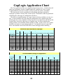
GapLogix Application Chart
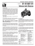
This 'Gap Application Chart' was compiled using all empty boxes. Variables that will
affect box performance include: Length/Height ratio, footprint size of box, weight,
weight distribution, non-convex surface, conveyor speed, box surface, and others.
This chart may be used as a guideline for determining initial gap required for
GapLogix to perform correctly at the various speeds. Performance cannot be guaranteed
considering the wide range of variables that can affect it.
This data was compiled setting a 48" gap to ensure each box would have to come to a
stop. Certain conditions will exist where the combination of all variables along with
specific gaps may cause a rhythmic rocking of product as it ramps down and back up that
wouldn't have occurred if it had came to a complete stop. For these conditions the
settings will have to be modified until the product is stable. Actual "worse case" product
should be tested prior to system design approval. Care should be taken to ensure that
boxes can transition across fixed SGR used to create initial gap without tumbling.
Minimum Gap Required for GapLogix
Discharge
Belt Speed
Length vs. Height Box Ratio
12" 2.25" x
cube
9" 6" lgth by 'x' ht. Boxes: 4 inches length by 'x' ht. (lgth / ht ratio)
1 to 1 4 to 1
100
150
200
250
300
350
400
450
500
2 to 1
1 to 1
3 to 1
2 to 1
1 to 1
1 to 2
2
2
2
2
2
2
4
6
4
6
8
12
18
24
26
4
6
8
10
12
14
18
4
6
8
10
12
18
18
6
10
12
4
6
8
10
12
18
18
4
6
8
10
12
18
24
6
10
12
24
24
* Minimum gap is based on boxes with evenly distributed weight and flat bottom.
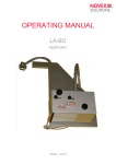
Recommended Settings for Application
Length vs. Height Box Ratio
12" cube 2.25" x 9"
6" lgth by 'x' ht.
Boxes: 4 inches length by 'x' ht. (lgth / ht ratio)
Discharge
1 to 1
4 to 1
2 to 1
1 to 1
3 to 1
2 to 1
1 to 1
1 to 2
Belt
Speed Time Ramp Time Ramp Time Ramp Time Ramp Time Ramp Time Ramp Time Ramp Time Ramp
100
150
200
250
300
350
400
450
500
.150 .500 .150 .500 .150 .500 .150 .500 .150 .500 .150 .750 .150 1.000 .150 2.500
.150
.120
.90
.70
.70
.70
.70
.350 .150 .250 .150 .250 .150 .600 .150 .350 .150 .350 .150 .750 .150 3.500
.200 .120 .200 .120 .200 .120 .400 .120 .200 .120 .200 .120 .350 .120 2.000
.200 .90 .150 .90 .180 .90 .275 .90 .200 .90 .200 .90 .275
.150 .70 .150 .70 .150
.70 .150 .70 .150
.150 .70 .120 .70 .120
.70 .120 .70 .120
.200 .70 .110 .70 .120
.70 .120 .70 .120
.250 .70 .120 .70 .120
.70 .110 .70 .120
III
Gap Logix Support Services
It is Hytrol’s goal to ensure your greatest possible satisfaction with the
operation of our controls. We are dedicated to providing you fast, friendly, and
dependable assistance.
Technical Support
Technical Support for this product extends from the date of shipment to
one year from this date. Support is available Monday through Friday during
normal business hours from 8 a.m. to 5 p.m. central time. Please include
serial number from label on the inside of panel door in all correspondence.
Technical Support Number
(870) 935 – 9444
(Please have serial number from label on the inside of
panel door ready before calling.)
Technical Support Fax
(870) 935 – 9460
(Please include serial number from label on the inside of
panel door in all correspondence.)
Correspondence Address
Attn: Technology Center / Gap Logix Support
Hytrol Conveyor Company, Inc.
2020 Hytrol Drive
Jonesboro, Arkansas 72401
(Please include serial number from label on the inside of panel door in all
correspondence.)
IV
HMI Software License Agreement
HYTROL’S HMI SOFTWARE LICENSE AGREEMENT
U.S.-Canada-Mexico
IMPORTANT, PLEASE READ THIS FIRST. THIS IS A LICENSE AGREEMENT.
Hytrol is willing to license the accompanying HMI software to you only upon the condition that you accept
all of the terms contained in this license agreement and any supplementary or unique license terms included
herewith ("Agreement").
YOUR USE OF THE SOFTWARE ALSO INDICATES YOUR ASSENT TO BE BOUND BY THE
LICENSE TERMS SET FORTH HEREIN. IF YOU DO NOT AGREE WITH THE TERMS AND
CONDITIONS OF THIS AGREEMENT, PROMPTLY CONTACT HYTROL CONVEYOR COMPANY
AT (870) 935-3700 OR BY MAIL AT: 2020 HYTROL DRIVE, JONESBORO, ARKANSAS 72401.
COPYING OF THIS SOFTWARE PROGRAM OR ITS DOCUMENTATION EXCEPT AS
PERMITTED BY THIS LICENSE IS STRICTLY PROHIBITED, CONSTITUTES COPYRIGHT
INFRINGEMENT UNDER THE LAWS OF YOUR COUNTRY, AND MAY SUBJECT YOU TO
LIABILITY FOR DAMAGES OR CRIMINAL PENALTIES.
1. Grant of License
Hytrol Conveyor Company, Inc. ("Hytrol") grants you a nonexclusive, nontransferable license to use the
enclosed program (the "Software") and its printed manual and other accompanying material
("Documentation") with the associated equipment owned by you or under your control, according to the
terms and conditions of this License Agreement. This License Agreement permits a single user to activate
and use one instance of this software on only one conveyor unit at one location at any one time.
Back-Up Copy: Regardless of which version of the Software you have acquired, you may make only one
archival (back-up) copy of the Software. Such archival copy may not be installed on another HMI, unless
express written consent is obtained from Hytrol. The archival copy may not be used or installed as long as
another copy of the Software is installed on any conveyor. If the Documentation is in printed form, it may
not be copied. If the Documentation is in electronic form, you may print out one (1) copy, which may not
be copied.
Upgrades: If this Software is labeled as an upgrade to software previously licensed to you, you must
destroy all copies of the replaced software, including any copies resident on your hard disk drive. Hytrol
reserves the right to require you to show satisfactory proof that previous copies of the Software have been
destroyed. Software patches, if any, provided to you by Hytrol or an authorized third party in connection
with the Software licensed to you hereunder, shall be subject to the terms and conditions of this License
Agreement unless otherwise specified at the time of delivery.
2. RESTRICTIONS:
THIS SOFTWARE MAY NOT BE USED OR TRANSFERRED OUTSIDE OF THE WESTERN
HEMISPHERE (U.S., Canada, Caribbean Islands and Latin America), REGARDLESS OF
WHETHER SUCH TRANSFER IS ACCOMPLISHED BY PHYSICAL OR ELECTRONIC
MEANS
You May Not:
1.
2.
copy the Software or Documentation except as permitted by this license.
distribute, rent, loan, lease, sell, sublicense or otherwise transfer all or part of the
Software, Documentation or any rights granted hereunder to any other person
without the prior written consent of Hytrol.
V
HMI Software License Agreement
3.
4.
5.
6.
remove, alter or obscure any proprietary notices, labels or marks from the
Software or Documentation.
modify, translate, adapt, arrange or create derivative works based on the
Software or Documentation for any purpose.
transmit the Software or Documentation over a network, by telephone or
electronically using any means.
reverse engineer, decompile or disassemble the Software or Documentation
3. Copyright
Title and copyrights to the Software, Documentation and accompanying materials and any copies
made by you remain with Hytrol. Unauthorized copying of the Software or Documentation, or
failure to comply with the above restrictions, will result in automatic termination of this license,
and may subject you to liability for damages or criminal penalties.
4. Limited Warranties
Hytrol warrants that for a 90 day period beginning on the date of delivery of the Software to you, the
Software will provide the facilities and functions generally described in the Documentation and that the
media on which the Software is furnished and the Documentation accompanying the Software will be free
from defects in materials and workmanship under normal use.
EXCEPT FOR THE ABOVE EXPRESS LIMITED WARRANTIES, HYTROL MAKES NO
WARRANTIES, EXPRESS, IMPLIED OR STATUTORY. HYTROL SPECIFICALLY DISCLAIMS
ANY OTHER WARRANTY INCLUDING THE IMPLIED WARRANTY OF MERCHANTABILITY OR
FITNESS FOR A PARTICULAR PURPOSE. HYTROL DOES NOT WARRANT THAT THE
OPERATION OF THE SOFTWARE WILL BE UNINTERRUPTED OR ERROR-FREE.
The above exclusions may not apply to you as some jurisdictions do not allow the exclusion of implied
warranties. In addition to the above warranty rights, you may also have other rights, which vary from
jurisdiction to jurisdiction.
Hytrol's entire liability and your exclusive remedy under this warranty will be, at Hytrol's option, to attempt
to correct or work around errors or to replace the defective media or documentation. This remedy is subject
to you contacting Hytrol within ninety (90) days from the date of delivery of the Software to you.
Following expiration of this ninety (90)-day period, Hytrol will replace any defective or damaged device in
return for payment of the cost of a replacement device plus a fee for handling and shipment.
5. LIMITATION OF LIABILITY
IN NO EVENT WILL HYTROL BE LIABLE FOR ANY LOSS OR DAMAGES OF ANY KIND,
INCLUDING LOSS OF DATA, LOST PROFITS, COST OF COVER OR OTHER SPECIAL,
INCIDENTAL, CONSEQUENTIAL OR INDIRECT DAMAGES ARISING OUT OF THE USE OR
INABILITY TO USE THE SOFTWARE OR DOCUMENTATION, HOWEVER CAUSED AND ON
ANY THEORY OF LIABILITY. THIS LIMITATION WILL APPLY EVEN IF HYTROL OR ANY
HYTROL RESELLER HAS BEEN ADVISED OF THE POSSIBILITY OF SUCH LOSS OR DAMAGE.
YOU ACKNOWLEDGE THAT THE LICENSE FEE REFLECTS THIS ALLOCATION OF RISK.
Hytrol shall have no responsibility or liability whatsoever arising from loss or theft of the Software.
Specifically, Hytrol shall not be obligated to replace any lost or stolen software. You are solely responsible
for safeguarding the Software from loss or theft and protecting your investment through insurance or
otherwise. The above limitation may not apply to you because some jurisdictions do not allow the
limitation or exclusion of liability for incidental or consequential damages.
6. Out of Country Sales
VI
HMI Software License Agreement
A. Canadian Sales
If you purchased this product in Canada, you agree to the following: The parties hereto confirm
that it is their wish that this Agreement, as well as other documents relating hereto, including
Notices, have been and shall be written in the English language only. Les parties aux présentes
confirment leur volonté que cette Convention de même que tous les documents y compris tout avis
qui s'y rattache, soient rédigés en langue anglaise.
B. Mexican Sales
If you purchased this product in Mexico, you agree to the following: The parties hereto confirm
that it is their wish that this Agreement, as well as other documents relating hereto, including
Notices, have been and shall be written in the English language only. Las partes aqui involucradas
confirman el deseo de que este Acuerdo, al igual que otros documentos relacionados al mismo
incluyendo todo tipo de Notas, sea y deba ser escrito únicamente en Inglés.
7. General.
A. You are responsible for configuration, management and operation of the Software.
B. This license shall terminate without further notice or action by Hytrol if you, the licensee, shall become
bankrupt, make an arrangement with your creditors or go into liquidation.
C. This Agreement shall not be governed by the UN Convention on Contracts for the Sale of Goods..
This Agreement is the entire agreement between us and supersedes any other communications or
advertising with respect to the Software and Documentation. If you have any questions, please contact
your Authorized Hytrol Distributor.
D. If any provision of these license conditions is found to be invalid or otherwise unenforceable, the
further conditions of this license will remain fully effective and the parties will be bound by
obligations which approximate, as closely as possible, the effect of the provision found invalid or
unenforceable, without being themselves invalid or unenforceable.
E. If any provision of this Agreement shall be held to be invalid or unenforceable for any reason by a
court of competent jurisdiction, the remaining provisions shall continue to be valid and enforceable. If
said court finds that any provision of this Agreement is invalid or unenforceable, but that by limiting
such provision it would become valid and enforceable, then such provision shall be deemed to be
written, construed, and enforced as so limited.
F. The laws of the State of Arkansas shall govern this agreement. Each party agrees that any dispute
arising hereunder shall be heard and litigated exclusively in the Federal and State courts located in
Jonesboro, Craighead County, Arkansas. Each party hereby consents to the jurisdiction of said courts.
G. If you have any questions please send written inquires to: Hytrol Conveyor Company, Inc.,
Technology Center, 2020 Hytrol Drive, Jonesboro, Arkansas 72401.
VII
VFD Software License Agreement
HYTROL’S VFD SOFTWARE LICENSE AGREEMENT
U.S.-Canada-Mexico
IMPORTANT, PLEASE READ THIS FIRST. THIS IS A LICENSE AGREEMENT.
Hytrol is willing to license the accompanying PLC software to you only upon the condition that you accept
all of the terms contained in this license agreement and any supplementary or unique license terms included
herewith ("Agreement").
YOUR USE OF THE SOFTWARE ALSO INDICATES YOUR ASSENT TO BE BOUND BY THE
LICENSE TERMS SET FORTH HEREIN. IF YOU DO NOT AGREE WITH THE TERMS AND
CONDITIONS OF THIS AGREEMENT, PROMPTLY CONTACT HYTROL CONVEYOR COMPANY
AT (870) 935-3700 OR BY MAIL AT: 2020 HYTROL DRIVE, JONESBORO, ARKANSAS 72401.
COPYING OF THIS SOFTWARE PROGRAM OR ITS DOCUMENTATION EXCEPT AS
PERMITTED BY THIS LICENSE IS STRICTLY PROHIBITED, CONSTITUTES COPYRIGHT
INFRINGEMENT UNDER THE LAWS OF YOUR COUNTRY, AND MAY SUBJECT YOU TO
LIABILITY FOR DAMAGES OR CRIMINAL PENALTIES.
1. Grant of License
Hytrol Conveyor Company, Inc. ("Hytrol") grants you a nonexclusive, nontransferable license to use the
enclosed program (the "Software") and its printed manual and other accompanying material
("Documentation") with the associated equipment owned by you or under your control, according to the
terms and conditions of this License Agreement. This License Agreement permits a single user to activate
and use one instance of this software on only one conveyor unit at one location at any one time.
Back-Up Copy: Regardless of which version of the Software you have acquired, you may make only one
archival (back-up) copy of the Software. Such archival copy may not be installed on another PLC, unless
express written consent is obtained from Hytrol. The archival copy may not be used or installed as long as
another copy of the Software is installed on any conveyor. If the Documentation is in printed form, it may
not be copied. If the Documentation is in electronic form, you may print out one (1) copy, which may not
be copied.
Upgrades: If this Software is labeled as an upgrade to software previously licensed to you, you must
destroy all copies of the replaced software, including any copies resident on your hard disk drive. Hytrol
reserves the right to require you to show satisfactory proof that previous copies of the Software have been
destroyed. Software patches, if any, provided to you by Hytrol or an authorized third party in connection
with the Software licensed to you hereunder, shall be subject to the terms and conditions of this License
Agreement unless otherwise specified at the time of delivery.
2. RESTRICTIONS:
THIS SOFTWARE MAY NOT BE USED OR TRANSFERRED OUTSIDE OF THE WESTERN
HEMISPHERE (U.S., Canada, Caribbean Islands and Latin America), REGARDLESS OF
WHETHER SUCH TRANSFER IS ACCOMPLISHED BY PHYSICAL OR ELECTRONIC
MEANS
You May Not:
1.
2.
3.
copy the Software or Documentation except as permitted by this license.
distribute, rent, loan, lease, sell, sublicense or otherwise transfer all or part of the
Software, Documentation or any rights granted hereunder to any other person
without the prior written consent of Hytrol.
remove, alter or obscure any proprietary notices, labels or marks from the
Software or Documentation.
VIII
VFD Software License Agreement
7.
8.
9.
modify, translate, adapt, arrange or create derivative works based on the
Software or Documentation for any purpose.
transmit the Software or Documentation over a network, by telephone or
electronically using any means.
reverse engineer, decompile or disassemble the Software or Documentation
3. Copyright
Title and copyrights to the Software, Documentation and accompanying materials and any copies
made by you remain with Hytrol. Unauthorized copying of the Software or Documentation, or
failure to comply with the above restrictions, will result in automatic termination of this license,
and may subject you to liability for damages or criminal penalties.
4. Limited Warranties
Hytrol warrants that for a 90 day period beginning on the date of delivery of the Software to you, the
Software will provide the facilities and functions generally described in the Documentation and that the
media on which the Software is furnished and the Documentation accompanying the Software will be free
from defects in materials and workmanship under normal use.
EXCEPT FOR THE ABOVE EXPRESS LIMITED WARRANTIES, HYTROL MAKES NO
WARRANTIES, EXPRESS, IMPLIED OR STATUTORY. HYTROL SPECIFICALLY DISCLAIMS
ANY OTHER WARRANTY INCLUDING THE IMPLIED WARRANTY OF MERCHANTABILITY OR
FITNESS FOR A PARTICULAR PURPOSE. HYTROL DOES NOT WARRANT THAT THE
OPERATION OF THE SOFTWARE WILL BE UNINTERRUPTED OR ERROR-FREE.
The above exclusions may not apply to you as some jurisdictions do not allow the exclusion of implied
warranties. In addition to the above warranty rights, you may also have other rights, which vary from
jurisdiction to jurisdiction.
Hytrol's entire liability and your exclusive remedy under this warranty will be, at Hytrol's option, to attempt
to correct or work around errors or to replace the defective media or documentation. This remedy is subject
to you contacting Hytrol within ninety (90) days from the date of delivery of the Software to you.
Following expiration of this ninety (90)-day period, Hytrol will replace any defective or damaged device in
return for payment of the cost of a replacement device plus a fee for handling and shipment.
5. LIMITATION OF LIABILITY
IN NO EVENT WILL HYTROL BE LIABLE FOR ANY LOSS OR DAMAGES OF ANY KIND,
INCLUDING LOSS OF DATA, LOST PROFITS, COST OF COVER OR OTHER SPECIAL,
INCIDENTAL, CONSEQUENTIAL OR INDIRECT DAMAGES ARISING OUT OF THE USE OR
INABILITY TO USE THE SOFTWARE OR DOCUMENTATION, HOWEVER CAUSED AND ON
ANY THEORY OF LIABILITY. THIS LIMITATION WILL APPLY EVEN IF HYTROL OR ANY
HYTROL RESELLER HAS BEEN ADVISED OF THE POSSIBILITY OF SUCH LOSS OR DAMAGE.
YOU ACKNOWLEDGE THAT THE LICENSE FEE REFLECTS THIS ALLOCATION OF RISK.
Hytrol shall have no responsibility or liability whatsoever arising from loss or theft of the Software.
Specifically, Hytrol shall not be obligated to replace any lost or stolen software. You are solely responsible
for safeguarding the Software from loss or theft and protecting your investment through insurance or
otherwise. The above limitation may not apply to you because some jurisdictions do not allow the
limitation or exclusion of liability for incidental or consequential damages.
6. Out of Country Sales
A. Canadian Sales
IX
VFD Software License Agreement
If you purchased this product in Canada, you agree to the following: The parties hereto confirm
that it is their wish that this Agreement, as well as other documents relating hereto, including
Notices, have been and shall be written in the English language only. Les parties aux présentes
confirment leur volonté que cette Convention de même que tous les documents y compris tout avis
qui s'y rattache, soient rédigés en langue anglaise.
B. Mexican Sales
If you purchased this product in Mexico, you agree to the following: The parties hereto confirm
that it is their wish that this Agreement, as well as other documents relating hereto, including
Notices, have been and shall be written in the English language only. Las partes aqui involucradas
confirman el deseo de que este Acuerdo, al igual que otros documentos relacionados al mismo
incluyendo todo tipo de Notas, sea y deba ser escrito únicamente en Inglés.
7. General.
A. You are responsible for configuration, management and operation of the Software.
B. This license shall terminate without further notice or action by Hytrol if you, the licensee, shall become
bankrupt, make an arrangement with your creditors or go into liquidation.
C. This Agreement shall not be governed by the UN Convention on Contracts for the Sale of Goods..
This Agreement is the entire agreement between us and supersedes any other communications or
advertising with respect to the Software and Documentation. If you have any questions, please contact
your Authorized Hytrol Distributor.
D. If any provision of these license conditions is found to be invalid or otherwise unenforceable, the
further conditions of this license will remain fully effective and the parties will be bound by
obligations which approximate, as closely as possible, the effect of the provision found invalid or
unenforceable, without being themselves invalid or unenforceable.
F.
If any provision of this Agreement shall be held to be invalid or unenforceable for any reason by a
court of competent jurisdiction, the remaining provisions shall continue to be valid and enforceable. If
said court finds that any provision of this Agreement is invalid or unenforceable, but that by limiting
such provision it would become valid and enforceable, then such provision shall be deemed to be
written, construed, and enforced as so limited.
F. The laws of the State of Arkansas shall govern this agreement. Each party agrees that any dispute
arising hereunder shall be heard and litigated exclusively in the Federal and State courts located in
Jonesboro, Craighead County, Arkansas. Each party hereby consents to the jurisdiction of said courts.
G. If you have any questions please send written inquires to: Hytrol Conveyor Company, Inc.,
Technology Center, 2020 Hytrol Drive, Jonesboro, Arkansas 72401.
X
Chapter 1: Installation
1
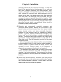
Installation
Inspection and inventory of components should be
conducted upon receiving packages. Check the number of
items received against the parts checklist below. Examine
condition of equipment to determine if any damage has
occurred during shipment.
Electrical Code: All motor controls and wiring shall conform
to the National Electrical Code (Article 670 or other applicable
articles) as published by the National Fire Protection
Association and as approved by the American Standards
Institute, Inc.
1.1
Parts Checklist
1 each
1 each
2 each
1 each
1.2
- Main Control Panel
- Panel Mounting Bracket
- Photo Eye Kit
– Encoder Cable
Mounting The Hardware
1.2.1 CONTROL DEVICE MOUNTING CONSIDERATIONS
A) Control stations should be so arranged and located that the
operation of the equipment is visible from them, and shall be
clearly marked or labeled to indicate the function controlled.
B) A conveyor shall not be started until employees in the area are
alerted by a signal or by a designated person that the
conveyor is about to start. When a conveyor would cause
injury when started and is automatically controlled or must be
controlled from a remote location, an audible device shall be
provided which can be clearly heard at all points along the
conveyor where personnel may be present. The warning
device shall be actuated by the controller device starting the
conveyor and shall continue for a required period of time
before the conveyor starts. A flashing light or similar visual
warning may be used in conjunction with or in place of the
audible device if more effective in particular circumstances.
Where system function would be seriously hindered or
1-1
Chapter 1: Installation
adversely affected by the required time delay or where the
intent of the warning may be misinterpreted (i.e., a work area
with many different conveyors and allied devices), clear,
concise, and legible warning shall be provided. The warning
shall indicate that conveyors and allied equipment may be
started at any time, that danger exists, and that personnel
must keep clear. The warnings shall be provided along the
conveyor at areas not guarded by position or location. If the
supplied warning device is not loud enough to easily be heard
the full length of the conveyor because of length and/or noise,
then either a louder device or an additional device should be
installed to properly warn personnel.
C) Remotely and automatically controlled conveyors, and
conveyors where operator stations are not manned or are
beyond voice and visual contact from drive areas, loading
areas, transfer points, and other potentially hazardous
locations on the conveyor path not guarded by location,
position, or guards, shall be furnished with emergency stop
buttons, pull cords, limit switches, or similar emergency stop
devices. Connection points are provided in the control panel
to put these ‘customer supplied’ devices in series with the EStop safety circuit. See the schematics provided for the proper
connection points.
All such emergency stop devices shall be easily identifiable
in the immediate vicinity of such locations unless guarded by
location, position, or guards. Where the design, function, and
operation of such conveyor clearly is not hazardous to
personnel, an emergency stop device is not required.
The emergency stop device shall act directly on the control
of the conveyor concerned and shall not depend on the
stopping of any other equipment. The emergency stop devices
shall be installed so that they cannot be overridden from other
locations.
D) Inactive and unused actuators, controllers, and wiring should
be removed from control stations and panel boards, together
with obsolete diagrams, indicators, control labels, and other
material that serve to confuse the operator.
1-2
Chapter 1: Installation
1.2.2 MOUNTING THE PANELS
A) The control panels have a NEMA 12 rating, which is a rating for use
in indoor environments that require a degree of protection against
dust, falling dirt, and dripping non-corrosive liquids. This rating
should be considered when determining where to mount the panels.
B) The main control panel should normally be mounted under the
discharge end of the gapper with the mounting brackets provided.
Take into consideration the length of the supplied encoder cable
before mounting the panel elsewhere.
1.2.3 SAFETY DEVICES
A) All safety devices, including wiring of electrical safety devices, shall
be arranged to operate in a “Fail-Safe” manner, that is, if power
failure or failure of the device itself would occur, a hazardous
condition must not result.
B) Emergency Stops and Restarts. Conveyor controls shall be so
arranged that, in case of emergency stop, manual reset or start at the
location where the emergency stop was initiated, shall be required of
the conveyor(s) and associated equipment to resume operation.
C) Before restarting a conveyor, which has been stopped because of an
emergency, an inspection of the conveyor shall be made and the
cause of the stoppage determined. The starting device shall be
locked out before any attempt is made to remove the cause of
stoppage, unless operation is necessary to determine the cause or to
safely remove the stoppage.
Refer to ANSI Z244.1-1982, American National Standard for
Personnel Protection – Lockout/Tagout of Energy Sources –
Minimum Safety Requirements and OSHA Standard Number
29 CFR 1910.147 “The Control of Hazardous Energy
(Lockout/Tagout).”
1-3
Chapter 1: Installation
1.3
Wiring Specifications
Power required to Gap Logix’s control panel is 15 amps at 460 VAC 3
phase with a range of 400 – 490 VAC. Improper voltage / wiring may
damage controls.
1.3.1
RECOMMENDED WIRE SIZES
A) Wiring from VFD to motor should be of suitable size and type to
carry up to 20 amps. Wire phasing is critical for correct
operation. Wires from U,V, and W from the VFD must go to U,
V, and W on the motor along with proper grounding. If phases
are not correct, the VFD will fault on “F-08” (Drive fault 08).
1.3.2
COMMUNICATING WITH OTHERS
A) Conveyor Run Signal The gapper will normally be started by
the central controls of the system, so that it can easily
coordinate the sequence in which all the conveyors in the
system start up. This “Run” signal is sent to Gap Logix on the
input “DI00”. Refer to Chapter 3: Communicating with Gap
Logix for the details on how to use this signal.
B) Ready Signal The “OK to feed” signal is sent after the gapper
is running, up to speed, and ready to be fed product. This
signal is a contact closure where the system’s voltage is
supplied to terminal DO01-C and it is sent back on terminal
DO01-NO when the contact is closed. Refer to Chapter 3:
Communicating with Gap Logix for the details on how to use this
signal.
1.4
Device Specifications
1.4.1
DEVICE REQUIREMENTS
A) The two photo eyes will be of the type and connected for ‘dark
operation’ (input “Off” until eye is blocked). The output signal
will be a sourcing (PNP) output. The amp draw for each photo
eye will not exceed 100 mA.
1-4
Chapter 1: Installation
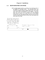
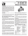
1.4.2
DEVICE MOUNTING LOCATIONS
A) The photo eyes should be mounted on the discharge belt of
the gapper as illustrated below. The discharge photo eye
should be mounted at the point where the tail end of a box will
lose contact with the discharge belt of the gapper. The other
photo eye should be mounted upstream from the discharge
photo eye at a point so no more than four of the smallest
products with the three gaps between them that will be pulled
across the speed gap ratio that can be in the zone between the
photo eyes at one time.
1-5
Chapter 2: Configuring Gap Logix for product
2
Configuring Gap Logix for Product
One of great features of Gap Logix is the ability to use this one
software package to optimize the gapper’s performance to your
unique product through the following parameters.
2.1 Access Protection
All setup screens are protected by a password. The password relocks
10 minutes after the correct password was entered. If you are unable to
change screens or change any values on a screen, access has expired
and you must re-enter the password.
To enter the password, press the F1 key to bring up the password
entry screen. After you have the password entry screen up with the
blinking cursor, you can enter the password. Press the left pointing
arrow key to bring up the first digit of the password, press the up pointing
arrow key to increment the first digit to the first value of the code, press
the left arrow key again to get to the second digit, press the up arrow key
to increment the second digit to the second value in the code, and repeat
the left and up arrow keys for digits three and four. After you have set
the four digits to the access code and they appear as four flashing
blocks, press the blue enter button. The password will time out after 10
minutes and will need to be re-entered.
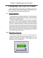
2.2 Explanation of Screens
After access is allowed you will be able to navigate through the
configuration parameters by pressing the right and left arrow keys. The
up and down arrow keys will be used to adjust the values. It is not
necessary to press the enter button.
The changes take affect
dynamically as you are changing them.
2-1
Chapter 2: Configuring Gap Logix for product
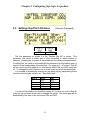
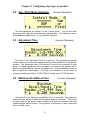
2.3 Settings Gap/Pitch Distance
X10.13
DI04
OFF
(Access: Password)
X10.14
DI05
OFF
The first parameter on screen 2 is the “Desired Gap #0” in inches. This
parameter can relate to either gap or pitch according to which method is
selected. If setting gap, the value is associated with the distance between boxes.
If setting pitch, the value is associated with the distance from the leading edge of
one box to the leading edge of the next box. The range is 0 – 90 inches. Gap #0
will be used to set the gap/pitch for all products while DI04 and DI05 inputs are
off. To change the value, press the up or down arrow key to set the desired gap.
It is possible to dynamically change the gap being set by manipulating these
inputs to select the gap value to use. See chart below.
GAP #
0
1
2
3
DI04
OFF
ON
OFF
ON
DI05
OFF
OFF
ON
ON
You can set the distance for Gap/Pitch values # 1-3 just as you did for Gap #0
using the up and down arrow keys to change the values. The active gap will be
determined by the state of the two inputs DI04 and DI05.
2-2
Chapter 2: Configuring Gap Logix for product
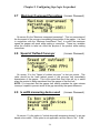
2.4 Gap / Pitch Mode Selection
(Access: Password)
The next parameter on screen 6 is the “Control Mode”. The up and down
arrow keys will toggle the value between gap and pitch. The distance is set in
first parameters gap/pitch (0 – 3) on screens 2 through 5.
2.5 Adjustment Time
(Access: Password)
On screen 7 the “Adjustment Time” is in seconds. This parameter along with
others is used to customize the speed and slope of the adjustment to the specific
product. The adjustment time is the amount of time for the correction to take
place. At higher speeds this value will have to be lower so the product will be
back to line speed before it leaves the gapper belt. At lower speeds you may be
able to adjust this value higher. If the gap is inconsistent or is too small, try
lowering the adjustment time. At 250 FPM it is usually around 0.250 seconds.
2.6 Minimum Accel/Decel Time
(Access: Password)
On screen 8 is the “Minimum Accel/Decel Time” in seconds. This parameter
adjusts the rate (slope) at which the belt speed ramps up and down. This can be
a lower value for low profile, heavy, stable boxes that can withstand the rapid
speed changes without rocking. For top heavy or tall boxes you may need to set
this at a higher value.
2-3
Chapter 2: Configuring Gap Logix for product
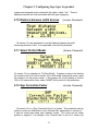
2.7
Maximum Overspeed Percentage (Access: Password)
On screen 9 is the “Maximum overspeed percentage”. This is a percentage of
the line speed of the conveyor immediately downstream of the gapper. It is used
in conjunction with the “Minimum Accel/Decel Time” to control the maximum
speed the gapper will reach while making a correction. These two variables
allow the controls to take into effect the physics of the product while making
corrections.
2.8 Speed of Outfeed Conveyor
(Access: Password)
On screen 10 is the “Speed of outfeed conveyor” in feet per minute. This
value should be the hand tached speed of the conveyor belt immediately
downstream of the gapper. This is the speed that Gap Logix will try to match
when the product is being transferred from the gapper to the next belt.
NOTE: It is important that the gapper belt exactly matches the down stream
conveyor’s speed to prevent errors in the gap caused by the speed difference.
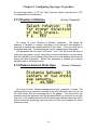
2.9 Is width measuring device used
(Access: Password)
On screen 11 is the option to “Include box width measuring devices” to set gap
based on box width. If this option is not applicable, set this value to “No”. If the
2-4
Chapter 2: Configuring Gap Logix for product
system was designed and provided with this option, select “Yes”. There is
additional devices and cost associated with this type of gapping.
2.10 Distance between width devices
(Access: Password)
On screen 12 is the parameter to set the distance between the width
measuring devices if used. If not applicable, just skip this parameter.
2.11 Select ProSort Model
(Access: Password)
On screen 13 is a selection for “ProSort Model”. If gapper is going to be feeding
the induction belt of a ProSort model 100 or 200 series sliding shoe sorter, make
the selection for the proper model. If this gapper will not be feeding a ProSort
100 or 200 series shoe sorter, select “NONE” as the value for this parameter.
2.12 Gap Correction Factor
(Access: Password)
On screen 14 is a “Gap Correction Factor” in inches. This parameter can be
used to correct any differences in the “Desired Gap” parameters on screens 2 5 and the actual gap being seen between boxes. This value can be either
positive or negative. For example, if the “Desired Gap” is set for 12 inches, but
2-5
Chapter 2: Configuring Gap Logix for product
the actual gap seen is 11.75”, the “Gap Correction Factor” could be set to 0.25”
to compensate for the difference.
2.13 Direction of Rotation
(Access: Password)
On screen 15 is the “Direction of Rotation” parameter. This allows the
selection of ‘forward’ or ‘reverse’ according to how the motor and gearbox is
mounted to achieve the needed direction of belt travel. The motor must be on
the downstream belt. This parameter will only be needed during initial setup.
This parameter will not correct VFD errors. If an “F-08” (Drive fault 08) error is
occurring, the problem may be caused by incorrect motor and/or encoder wiring.
See the installation and troubleshooting sections for more detailed information of
wiring and fault diagnostics. Before this parameter is needed the conveyor
should be able to run without errors.
2.14 Distance between Photo Eyes
(Access: Password)
On screen 16 is the “Distance between photo eyes” parameter in inches. The
discharge photo eye should be mounted at the point where the tail end of a box
will lose contact with the discharge belt of the gapper. The other photo eye
should be mounted upstream from the discharge photo eye at a point so no more
than four of the smallest products with the three gaps between them that will be
pulled across the speed gap ratio that can be in the zone between the photo
eyes at one time.
2-6
Chapter 3: Communicating with Gap Logix
Communicating with Gap Logix
3
Gap Logix provides the ability to interlock signals to allow for
flexible integration into any conveyor system.
3.1 Interlock Signals with Others
There are two signal interlocks provided to allow the system to
coordinate the gapper with the other associated conveyors. The wiring
connections for these signals are explained in Chapter 1: Installation.
•
•
Conveyor Run Signal: The “Conveyor Run Signal” can be sent to
Gap Logix through a dry contact closure. This allows the system to
start and stop the gapper. When the signal is dropped the gapper will
stop. This “Run” signal is sent to Gap Logix on the input “DI00”.
Once the gapper is started, the central control system should wait until
it receives the “Ready, OK to Feed” signal before starting the upstream
conveyors.
Conveyor Ready Signal: The “Conveyor Ready Signal” will be sent to
the system after the gapper is running and up to speed. This signal is a
contact closure where the system’s voltage is supplied to terminal
DO01-C and it is sent back on terminal DO01-NO when the contact is
closed.
3-1
Chapter 4: Operating Your Gapper
4
Operating Your Gapper
Once the gapper has been initially calibrated to optimize the
performance based on the product in this application, there
should be no need to make further changes in the future. The
gapper will be started and stopped remotely by the main system
and Gap Logix will automatically make corrections based on the
values of the parameters set during initial calibration.
Normally a system will set a specific gap 100% of the time.
Occasionally variables such as running different size products at
different times of day, allowing for a different number of printand-apply applicators to be in production at any one time, etc.
could dictate being able to dynamically change the gap. There
can be a maximum of four preset gap settings and can be
selected by a combination of input signals. See chapter 2 in
section 2.3 for details on configuring these parameters.
4-1
Chapter 5: Using the MOVIDRIVE® Keypad
5
Using the MOVIDRIVE® Keypad
The Movidrive keypad can be used for multiple functions. You
can use it for troubleshooting the VFD, saving, and loading the
program and parameters. This section will explain how to use
the keypad to perform these functions.
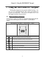
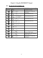
5.1 Basic functions of the keys
This document is a step-by-step example for saving and loading parameter files and
programs with the DBG Keypad for the MOVIDRIVE® and MOVIDRIVE®
compact.
DBG Keypad for MOVIDRIVE® and MOVIDRIVE® compact
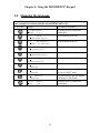
General function of the keys.
Next menu command or increase value in edit mode.
Previous menu command or decrease value in edit mode.
One menu level down or activate edit mode for the menu command.
One menu level up or deactivate edit mode for the menu command.
Cancel and return to main display.
Pressing this key in the event of a fault gives direct access to Parameter
840 [Manual Reset].
5-1
Chapter 5: Using the MOVIDRIVE® Keypad
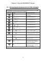
5.2 Changing the language
Should the keypad display come up in a language other in English, do the following
(this example is in German with the default SHORT MENU on).
Press Key
Display
REGLERSPERRE
STROM: 0 A
Description/Comments
Press the Q key to return to the
main display.
840/
NEIN
MANUELLER RESTE
Press the down arrow key.
835/
KEINEREAKT
REAKT. TF-MELDUNG
Press the down arrow key.
820/
EIN
4-Q-BETRIEB1
Press the down arrow key.
803/
AUS
PARAMETWESPERRE
Press the down arrow key.
802/
NEIN
WERSEINSELLUNG
Press the down arrow key.
801/ DEUTSCH
SPRACHE
Press the down arrow key.
801/ DEUTSCH
SPRACHE
Press the right arrow key. This will
put you in “EDIT” mode.
801/ ENGLISH
LANQUAGE
Press the up arrow key; the display
will change to ENGLISH.
CONTR. INHIBT
CURR.: 0 A
Press the Q key to return to the
main display.
5-2
Chapter 5: Using the MOVIDRIVE® Keypad
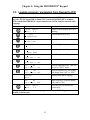
5.3 Accessing full parameter set
To access the full parameter set of the drive the SHORT MENU must be set to OFF
Press Key
Display
CONTR. INHIBT
CURR.: 0 A
Description/Comments
Press the Q key to return to the
main display.
840/
0FF
MANUAL RESET
Press the down arrow key.
835/
NO RESPONSE
RESP. TF-SIGNAL
Press the down arrow key.
820/
ON
4-QUADR-OPER.1
Press the down arrow key.
803/
OFF
PARAMETER LOCK
Press the down arrow key.
802/
NO
FACTORY SETTING
Press the down arrow key.
801/ ENGLISH
LANGUAGE
Press the down arrow key.
800/
ON
SHORT MENU
Press the down arrow key.
800/
ON
SHORT MENU
Press the right arrow key. This will
put you in “EDIT” mode.
800/
OFF
SHORT MENU
Press the up arrow key to turn the
SHORT MENU off.
CONTR. INHIBT
CURR.: 0 A
Press the Q key to return to the
main display.
5-3
Chapter 5: Using the MOVIDRIVE® Keypad
5.4 Saving program & parameters from VFD to Keypad
Following is the procedure to save the inverter program from the drive to the DBG
Keypad. This can be done while the drive is running:
Press Key
-- WAIT--
—
Display
CONTR. INHIBT
CURR.: 0 A
Description/Comments
Press the Q key to return to the
main display.
9.. IPOS
PARAMETERS
Press the down arrow key.
8.. UNIT
FUNCTIONS
Press the down arrow key.
80. SETUP
Press the right arrow key.
800
OFF
SHORT MENU
Press the right arrow key.
807
NO
COPY MDX--> DBG
Press the down arrow key.
807
NO
COPY MDX--> DBG
Press the right arrow key. This will
put you in “EDIT” mode.
807
YES
COPY MDX--> DBG
Press the up arrow key, the display
will change from “NO” to “YES”.
COPYING
DATA
Display while data is copying.
807
NO
COPY MDX--> DBG
When copying is complete display
will return to “NO”.
CONTR. INHIBT
CURR.: 0 A
Press the Q key to return to the
main display (display example if
the drive is not running).
SPEED:
CURR.:
Press the Q key to return to the
main display (display example if
the drive is running).
1500 rpm
1.68 A
The parameter file and any inverter program are now saved on the DBG Keypad.
5-4
Chapter 5: Using the MOVIDRIVE® Keypad
5.5 Loading program / parameters from Keypad to VFD
Following is the procedure to copy the program from the DBG Keypad to the
inverter. NOTE: input DI00 (terminal X13:1 on the MOVIDRIVE® or terminal
X10:9 on the MOVIDRIVE® compact must be low (24VDC must be removed while
copying).
Key
-- WAIT --
—
Display
CONTR. INHIBT
CURR.: 0 A
Description
Returns to main display (drive not
running)
9.. IPOS
PARAMETERS
Press the down arrow key.
8.. UNIT
FUNCTIONS
Press the down arrow key.
80. SETUP
Press the right arrow key.
800
OFF
SHORT MENU
Press the right arrow key.
807
NO
COPY MDX--> DBG
Press the down arrow key.
806
NO
COPY DBG--> MDX
Press the down arrow key.
806
NO
COPY DBG--> MDX
Press the right arrow key. This will
put you in “EDIT” mode.
806
YES
COPY DBG--> MDX
Press the up arrow key, the display
will change from “NO” to “YES”.
COPYING
DATA
Display while data is copying.
806
NO
COPY DBG--> MDX
When copying is complete display
will return to “NO”.
CONTR. INHIBT
CURR.: 0 A
Press the Q key to return to the
main display.
The parameter file and any inverter program saved on the DBG Keypad are now
loaded on the inverter.
5-5
Chapter 6: Troubleshooting with Gap Logix
6
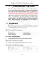
Troubleshooting Gap Logix
Gap Logix will immediately display an error message whenever
one of the conditions below occurs. The gapper will immediately
shut down when one of these conditions occur. Ensure that the
cause of the error condition has been remedied and all
personnel are clear before attempting to restart the sorter. After
repairing the condition that caused the error, go through section
6.3 of this chapter or the steps explained in chapter 5 for
resetting errors. Warning: the gapper is started by the main
control system; it may start at any time. Disconnect and lock out
power before performing any maintenance on the gapper to
ensure the unit will not start unexpectedly.
6.1 Error Messages
Error messages most likely to occur are listed below with a “Possible
Cause”, and a “Corrective Action”, for all other error messages please refer
to the MOVIDRIVE® compact manual for details.
6.1.1 Drive Fault-01: Overcurrent
Possible Cause
Short circuit on output
Defective output stage
Corrective Action
Rectify the short circuit
Contact SEW Service
6.1.2 Drive Fault-02: Unused
Please refer to the MOVIDRIVE® compact manual for details.
6.1.3 Drive Fault-03: Ground Fault
Please refer to the MOVIDRIVE® compact manual for details.
6.1.4 Drive Fault-04: Brake Chopper
Possible Cause
Excessive regenerative power
Brake resistor circuit interrupted
Brake chopper defective
Corrective Action
Extend deceleration ramps
Check brake resistor wiring
®
Replace MOVIDRIVE
6-1
Chapter 6: Troubleshooting with Gap Logix
6.1.5 Drive Fault-05: Unused
Please refer to the MOVIDRIVE® compact manual for details.
6.1.6 Drive Fault-06: Unused
Please refer to the MOVIDRIVE® compact manual for details.
6.1.7 Drive Fault-07: Over Voltage
Please refer to the MOVIDRIVE® Compact manual for details.
6.1.8 Drive Fault-08: n-Monitoring (Over Current)
Possible Cause
Incorrect direction of rotation
NOTE: This situation will only occur during
initial start-up
Problem with encoder connection
Insufficient drive current, the unit is unable to
maintain the speed setpoint
Corrective Action
•
Swap two of the output leads from the
MOVIDRIVE® to the motor. If the conveyor
direction is not correct this can be altered
by setting the Motor Sense of Rotation to
‘ON’ (MOVIDRIVE® parameter 350, this
can also be changed on the EXOR, see
section 2.13)
Check encoder wiring to ensure proper
connection and integrity of cables and
connections
• Reduce load
• Increase Speed Monitoring Delay Time
(MOVIDRIVE® parameter 501)
• Increase Current Limit (MOVIDRIVE®
parameter 303 up to the maximum of
150%)
• Insure that the motor is receiving voltage
from the MOVIDRIVE ® (i.e. no intervening
disconnect is off, motor terminals are
properly connected)
6.1.9 Drive Fault-09: Commissioning
Please refer to the MOVIDRIVE® compact manual for details.
6.1.10 Drive Fault-10: IPOS - ILLOP
Please refer to the MOVIDRIVE® compact manual for details.
6-2
Chapter 6: Troubleshooting with Gap Logix
6.1.11 Drive Fault-11: Over Temperature
Possible Cause
Thermal overload of MOVIDRIVE®
Corrective Action
Insure there is adequate cooling in the
enclosure
6.1.12 Drive Fault-12: Unused
Please refer to the MOVIDRIVE® compact manual for details.
6.1.13 Drive Fault-13: Control Signal
Please refer to the MOVIDRIVE® compact manual for details.
6.1.14 Drive Fault-14: Encoder Signal
Possible Cause
Corrective Action
Encoder cable or shield not connected
correctly
Short circuit or open circuit in encoder cable
Defective encoder
Check encoder cable and shield for correct
connection
Check encoder cable
Replace encoder
6.1.15 Drive Fault-15: Internal 24 VDC
Please refer to the MOVIDRIVE® compact manual for details.
6.1.16 Drive Fault-16: Unused
Please refer to the MOVIDRIVE® compact manual for details.
6.1.17 Drive Fault-17: System Fault
Please refer to the MOVIDRIVE® compact manual for details.
6.1.18 Drive Fault-18: System Fault
Please refer to the MOVIDRIVE® compact manual for details.
6.1.19 Drive Fault-19: System Fault
Please refer to the MOVIDRIVE® compact manual for details.
6.1.20 Drive Fault-20: System Fault
6-3
Chapter 6: Troubleshooting with Gap Logix
Please refer to the MOVIDRIVE® compact manual for details.
6.1.21 Drive Fault-21: System Fault
Please refer to the MOVIDRIVE® compact manual for details.
6.1.22 Drive Fault-22: System Fault
Please refer to the MOVIDRIVE® compact manual for details.
6.1.23 Drive Fault-23: System Fault
Please refer to the MOVIDRIVE® compact manual for details.
6.1.24 Drive Fault-24: System Fault
Please refer to the MOVIDRIVE® compact manual for details.
6.1.25 Drive Fault-25: EEPROM
Please refer to the MOVIDRIVE® compact manual for details.
6.1.26 Drive Fault-26: Ext. Terminal
Please refer to the MOVIDRIVE® compact manual for details.
6.1.27 Drive Fault-27: Limit Switches Missing
Please refer to the MOVIDRIVE® compact manual for details.
6.1.28 Drive Fault-28: Fieldbus Timeout
Please refer to the MOVIDRIVE® compact manual for details.
6.1.29 Drive Fault-29: Limit Switch Reached
Please refer to the MOVIDRIVE® compact manual for details.
6.1.30 Drive Fault-30: Time Out
Please refer to the MOVIDRIVE® compact manual for details.
6-4
Chapter 6: Troubleshooting with Gap Logix
6.1.31 Drive Fault-31: TF Sensor
Please refer to the MOVIDRIVE® compact manual for details.
6.1.32 Drive Fault-32: IPOS Index Overrun
Please refer to the MOVIDRIVE® compact manual for details.
6.1.33 Drive Fault-33: Set Point Source
Please refer to the MOVIDRIVE® compact manual for details.
6.1.34 Drive Fault-34: Unused
Please refer to the MOVIDRIVE® compact manual for details.
6.1.35 Drive Fault-35: Operating Mode
Please refer to the MOVIDRIVE® compact manual for details.
6.1.36 Drive Fault-36: Unused
Please refer to the MOVIDRIVE® compact manual for details.
6.1.37 Drive Fault-37: System Watchdog
Please refer to the MOVIDRIVE® compact manual for details.
6.1.38 Drive Fault-38: System Software
Please refer to the MOVIDRIVE® compact manual for details.
6.1.39 Drive Fault-39: Reference Travel
Please refer to the MOVIDRIVE® compact manual for details.
6.1.40 Drive Fault-40: Unused
Please refer to the MOVIDRIVE® compact manual for details.
6.1.41 Drive Fault-41: Unused
Please refer to the MOVIDRIVE® compact manual for details.
6-5
Chapter 6: Troubleshooting with Gap Logix
6.1.42 Drive Fault-42: Lag Error
Please refer to the MOVIDRIVE® compact manual for details.
6.1.43 Drive Fault-43: Timeout RS-485
Possible Cause
Communication between EXOR and
MOVIDRIVE® interrupted
Corrective Action
Check connection between EXOR and
®
MOVIDRIVE
6.1.44 Drive Fault-44: Unit Utilization
Please refer to the MOVIDRIVE® compact manual for details.
6.1.45 Drive Fault-45: Initialization
Please refer to the MOVIDRIVE® compact manual for details.
6.1.46 Drive Fault-46: Unused
Please refer to the MOVIDRIVE® compact manual for details.
6.1.47 Drive Fault-47: SBUS Timeout
Please refer to the MOVIDRIVE® compact manual for details.
6.1.48 Drive Fault-48: Unused
Please refer to the MOVIDRIVE® compact manual for details.
6.1.49 Drive Fault-49: Unused
Please refer to the MOVIDRIVE® compact manual for details.
6.1.50 Drive Fault-50: Unused
Please refer to the MOVIDRIVE® compact manual for details.
6.1.51 Drive Fault-51: Unused
Please refer to the MOVIDRIVE® compact manual for details.
6-6
Chapter 6: Troubleshooting with Gap Logix
6.1.52 Drive Fault-52: Unused
Please refer to the MOVIDRIVE® compact manual for details.
6.1.53 Drive Fault-53: Unused
Please refer to the MOVIDRIVE® compact manual for details.
6.1.54 Drive Fault-54: Unused
Please refer to the MOVIDRIVE® compact manual for details.
6.1.55 Drive Fault-55: Unused
Please refer to the MOVIDRIVE® compact manual for details.
6.1.56 Drive Fault-56: Unused
Please refer to the MOVIDRIVE® compact manual for details.
6.1.57 Drive Fault-57: Unused
Please refer to the MOVIDRIVE® compact manual for details.
6.1.58 Drive Fault-58: Unused
Please refer to the MOVIDRIVE® compact manual for details.
6.1.59 Drive Fault-59: Unused
Please refer to the MOVIDRIVE® compact manual for details.
6.1.60 Drive Fault-60: Unused
Please refer to the MOVIDRIVE® compact manual for details.
6.1.61 Drive Fault-61: Unused
Please refer to the MOVIDRIVE® compact manual for details.
6.1.62 Drive Fault-62: Unused
Please refer to the MOVIDRIVE® compact manual for details.
6-7
Chapter 6: Troubleshooting with Gap Logix
6.1.63 Drive Fault-63: Unused
Please refer to the MOVIDRIVE® compact manual for details.
6.1.64 Drive Fault-64: Unused
Please refer to the MOVIDRIVE® compact manual for details.
6.1.65 Drive Fault-65: Unused
Please refer to the MOVIDRIVE® compact manual for details.
6.1.66 Drive Fault-66: Unused
Please refer to the MOVIDRIVE® compact manual for details.
6.1.67 Drive Fault-67: Unused
Please refer to the MOVIDRIVE® compact manual for details.
6.1.68 Drive Fault-68: Unused
Please refer to the MOVIDRIVE® compact manual for details.
6.1.69 Drive Fault-69: Unused
Please refer to the MOVIDRIVE® compact manual for details.
6.1.70 Drive Fault-70: Unused
Please refer to the MOVIDRIVE® compact manual for details.
6.1.71 Drive Fault-71: Unused
Please refer to the MOVIDRIVE® compact manual for details.
6.1.72 Drive Fault-72: Unused
Please refer to the MOVIDRIVE® compact manual for details.
6.1.73 Drive Fault-73: Unused
6-8
Chapter 6: Troubleshooting with Gap Logix
Please refer to the MOVIDRIVE® compact manual for details.
6.1.74 Drive Fault-74: Unused
Please refer to the MOVIDRIVE® compact manual for details.
6.1.75 Drive Fault-75: Unused
Please refer to the MOVIDRIVE® compact manual for details.
6.1.76 Drive Fault-76: Unused
Please refer to the MOVIDRIVE® compact manual for details.
6.1.77 Drive Fault-77: IPOS Control Word
Please refer to the MOVIDRIVE® compact manual for details.
6.1.78 Drive Fault-78: IPOS SW Limit Switches
Please refer to the MOVIDRIVE® compact manual for details.
6.1.79 Drive Fault-79: Unused
Please refer to the MOVIDRIVE® compact manual for details.
6.1.80 Drive Fault-80: Unused
Please refer to the MOVIDRIVE® compact manual for details.
6.1.81 Drive Fault-81: Start Condition
Please refer to the MOVIDRIVE® compact manual for details.
6.1.82 Drive Fault-82: Output Open
Please refer to the MOVIDRIVE® compact manual for details.
6.1.83 Drive Fault-83: Unused
Please refer to the MOVIDRIVE® compact manual for details.
6.1.84 Drive Fault-84: Motor Protection
6-9
Chapter 6: Troubleshooting with Gap Logix
Please refer to the MOVIDRIVE® compact manual for details.
6.1.85 Drive Fault-85: Copy
Please refer to the MOVIDRIVE® compact manual for details.
6.1.86 Drive Fault-86: Unused
Please refer to the MOVIDRIVE® compact manual for details.
6.1.87 Drive Fault-87: Unused
Please refer to the MOVIDRIVE® compact manual for details.
6.1.88 Drive Fault-88: Flying Start
Please refer to the MOVIDRIVE® compact manual for details.
6.1.89 Drive Fault-89: Unused
Please refer to the MOVIDRIVE® compact manual for details.
6.1.90 Drive Fault-90: Unused
Please refer to the MOVIDRIVE® compact manual for details.
6.1.91 Drive Fault-91: Unused
Please refer to the MOVIDRIVE® compact manual for details.
6.1.92 Drive Fault-92: Unused
Please refer to the MOVIDRIVE® compact manual for details.
6.1.93 Drive Fault-93: Unused
Please refer to the MOVIDRIVE® compact manual for details.
6.1.94 Drive Fault-94: Check Sum EEPROM
Please refer to the MOVIDRIVE® compact manual for details.
6-10
Chapter 6: Troubleshooting with Gap Logix
6.1.95 Drive Fault-95: Unused
Please refer to the MOVIDRIVE® compact manual for details.
6.1.96 Drive Fault-96: Unused
Please refer to the MOVIDRIVE® compact manual for details.
6.1.97 Drive Fault-97: Unused
Please refer to the MOVIDRIVE® compact manual for details.
6.1.98 Drive Fault-98: Unused
Please refer to the MOVIDRIVE® compact manual for details.
6.1.99 Drive Fault-99: Unused
Please refer to the MOVIDRIVE® compact manual for details.
6.2 Symptoms and Solutions
6.2.1
Gaps are not being corrected
•
•
Check to make sure that both photo eyes are aligned with their
reflectors and are working properly.
Check the distance entered on screen 16, as explained in section 2.14,
to ensure that the entered value is exactly equal to the distance
between the centers of the photo eyes.
6-11
Chapter 6: Troubleshooting with Gap Logix
• Check that the photo eyes are properly wired.
6.2.2
Gapper will not start
•
•
•
Check to ensure the “Run” signal from the system is present on input
DI00.
Check to ensure that the VFD is not faulted. The indicator on the front
of the VFD should not be red. If there is a fault it should be displayed
on the main screen on the display also.
Check to ensure the proper voltage is present on all three legs of the
supply power.
6.3 Resetting Errors
If an error occurs on the Gapper’s VFD the status light on the VFD will be
red instead of green or amber. It this occurs, the VFD has faulted. Note
the error displayed and try cycling power to reset the error. If the error is
still present after powering up, the cause of the error must be corrected
before it can be cleared. Look up the error code in the instruction manual to
determine the cause of the error. Correct the cause of the error.
You may directly view the fault code on the VFD using these steps.
Unplug the communication module on the front of the VFD and put in the
DBG keypad provided. Write down the error code displayed on the DBG
keypad for future reference. Press the “E” push button will take you to the
“Manual Reset” parameter (840). Press the up arrow key to reset the error.
If this clears the error, you can attempt to restart the gapper to checks its
operation. Refer to chapter 5 for a more detailed step-by-step procedure
for resetting an error with the DBG keypad.
You must remove the DGB keypad and replace it with the
communication module before the HMI display will be functional. The
gapper will still function while the display is unplugged. The HMI display is
only necessary to make parameter changes.
6-12
Gap Logix
Notes
Gap Logix