1
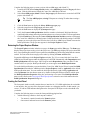
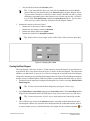
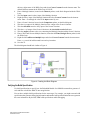
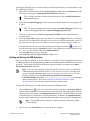
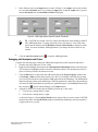
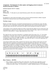
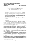
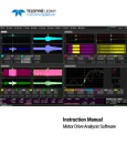
Getting Started with the NI LabVIEW™ Embedded
Module for ARM Microcontrollers
The LabVIEW Embedded Module for ARM Microcontrollers is a comprehensive graphical development
environment for embedded design. This module seamlessly integrates the LabVIEW graphical
development environment and ARM microcontrollers. You can lower development costs and achieve
faster development times by using the Embedded Module for ARM Microcontrollers to program ARM
targets.
This module builds on NI LabVIEW Embedded technology, which facilitates dataflow graphical
programming for embedded systems and includes hundreds of analysis and signal processing functions,
integrated I/O, and an interactive debugging interface. With the Embedded Module for ARM
Microcontrollers, you can view live front panel updates using JTAG, serial, or TCP/IP. The Embedded
Module for ARM Microcontrollers generates C code from the LabVIEW block diagram, builds that
code into an application using Keil µVision, and runs the application on ARM targets.
This manual includes system requirements, installation instructions, new features, and a step-by-step
tutorial that shows you how to build, run, and debug an ARM application.
Contents
System Requirements............................................................................................................................1
Installing the Embedded Module for ARM Microcontrollers..............................................................2
Evaluating the Embedded Module for ARM Microcontrollers............................................................3
Installing the MCB2300 Evaluation Board...........................................................................................3
Installing the LM3S8962 Evaluation Board.........................................................................................5
What's New...........................................................................................................................................7
Tutorial for the Embedded Module for ARM Microcontrollers...........................................................7
Creating the LabVIEW Project.....................................................................................................7
Reviewing the Project Explorer Window.....................................................................................8
Creating the Front Panel...............................................................................................................8
Creating the Block Diagram.........................................................................................................9
Verifying the Build Specification................................................................................................10
Building and Running the ARM Application.............................................................................11
Debugging with Breakpoints and Probes....................................................................................12
Using Elemental I/O...................................................................................................................13
Where to Go from Here......................................................................................................................15
System Requirements
The Embedded Module for ARM Microcontrollers has the following system requirements:
•
One of the following operating systems:
–
Windows 7 (32-bit)
–
Windows Vista (32-bit)
–
Windows XP (32-bit)
–
Windows Server 2003 R2 (32-bit)
Note The Embedded Module for ARM Microcontrollers does not support Windows
NT/Me/98/95/2000, Windows Server non-R2 editions, or the Windows Server 2008 R2
edition.
•
•
•
RealView Microcontroller Development Kit, including Keil μVision4
LabVIEW 2010 Full or Professional Development System
Keil ULINK2 USB-JTAG adaptor
Refer to the LabVIEW Release Notes, available by selecting Start»All Programs»National
Instruments»LabVIEW»LabVIEW Manuals and opening LV_Release_Notes.pdf, for information
about LabVIEW development system requirements.
Installing the Embedded Module for ARM Microcontrollers
Complete the following steps to install the Embedded Module for ARM Microcontrollers.
Note The Embedded Module for ARM Microcontrollers installer automatically installs
LabVIEW if it is not already installed. The Embedded Module for ARM Microcontrollers
also automatically installs the RealView Microcontroller Development Kit, which includes
Keil μVision.
1.
2.
3.
4.
Log in as an administrator or as a user with administrator privileges.
Insert the NI LabVIEW Embedded Module for ARM Microcontrollers DVD. If the installer does
not automatically begin, double-click autorun.exe on the DVD to begin installation.
Select Install LabVIEW Embedded Module for ARM Microcontrollers.
Follow the instructions on the screen for installing the Embedded Module for ARM Microcontrollers.
Note During installation, the installer automatically launches the RealView
Microcontroller Development Kit installer.
5.
Follow the activation instructions for the Embedded Module for ARM Microcontrollers that appear
on the screen. Skip this step if you are evaluating the Embedded Module for ARM Microcontrollers.
Refer to the Evaluating the Embedded Module for ARM Microcontrollers section for more
information about running in evaluation mode.
Tip You also can use the NI License Manager, available by selecting Start»All
Programs»National Instruments»NI License Manager, to activate National Instruments
products. Refer to the National Instruments License Manager Help, available by selecting
Help»Contents in the NI License Manager, for more information about activating
NI products.
6.
7.
Restart the computer when the installer prompts you and log in as an administrator or as a user with
administrator privileges.
Activate the Keil μVision License ID Code (LIC). Complete the following steps to activate the
LIC. Skip this step if you are evaluating the Embedded Module for ARM Microcontrollers. Refer
to the Evaluating the Embedded Module for ARM Microcontrollers section for more information
about running in evaluation mode.
a. Launch Keil μVision by selecting Start»All Programs»Keil uVision.
b. Select File»License Management to display the License Management dialog box.
c. Click the Help button to open the ARM Development Tools help file.
Getting Started with LabVIEW Embedded Module
for ARM Microcontrollers
2
ni.com
d.
e.
f.
Follow the instructions for obtaining a single-user license. You need an internet connection
and a product serial number (PSN) to activate the license. The PSN is an alphanumeric value
located on the Certificate of Ownership or license card included with purchased products.
After you add the LIC to the License Management dialog box, click the Close button to close
the dialog box.
Exit Keil μVision.
Refer to the Keil Web site at www.keil.com/license for more information about activating
Keil μVision.
Evaluating the Embedded Module for ARM Microcontrollers
You can install and evaluate the Embedded Module for ARM Microcontrollers for 60 days. When you
run the Embedded Module for ARM Microcontrollers in evaluation mode, LabVIEW includes the
following limitations:
Note If you are evaluating the Embedded Module for ARM Microcontrollers with an already
licensed and activated LabVIEW development system, these limitations apply only to ARM
targets, VIs, and applications.
•
•
•
A 60-day time limit until the evaluation version expires—While not activated, LabVIEW prompts
you to activate the product each time you launch LabVIEW. You also receive a warning when you
build a VI into an application until you activate the Keil µVision License ID Code (LIC). After the
evaluation period for LabVIEW expires, you are no longer able to launch LabVIEW until you
purchase and activate the Embedded Module for ARM Microcontrollers.
A KB size limit—Any applications you create and build with LabVIEW and Keil μVision are
limited to 128 KB.
An evaluation version watermark during the 60-day time limit—All user VIs and controls
contain an evaluation watermark.
Installing the MCB2300 Evaluation Board
You need the following items to use the MCB2300 evaluation board with JTAG emulation:
•
MCB2300 board
•
A PC with two unused USB ports: one port to supply power to the MCB2300 board and the other
port to perform ULINK2 USB-JTAG downloading and debugging
•
ULINK2 USB-JTAG adaptor
•
Two USB serial cables, each no longer than 10 feet
Refer to the hardware documentation for required accessories such as cables and adaptors.
Caution Be careful when removing the board from the package and handling the board to
avoid the discharge of static electricity, which might damage some components.
Figure 1 shows the location of some of the parts on the MCB2300 evaluation board. Refer to the hardware
documentation for more information about the evaluation board.
© National Instruments Corporation
3
Getting Started with LabVIEW Embedded Module
for ARM Microcontrollers
Figure 1. Locating Parts for the MCB2300 Installation
1 USB Connector
4 Potentiometer (Analog Input AD0) 7 ISP Jumper
2 Power LED
5 Contrast Control for LCD
3 JTAG Connector
6 Ethernet Connector
8 RST Jumper
Complete the following steps to install the board. You do not have to open the computer case to install
the board.
1. Verify that you have Keil μVision installed. μVision is a part of the RealView Microcontroller
Development Kit. You can look for the Keil\uvx directory on the hard disk, where x is the µVision
version, or select Start»All Programs and locate the shortcut to Keil μVision. Do not launch
μVision from the shortcut if you are going to use LabVIEW. Refer to the Installing the Embedded
Module for ARM Microcontrollers section for information about installing the RealView
Microcontroller Development Kit.
2. Connect the ULINK2 USB-JTAG adaptor to a USB port on the host computer. If you are connecting
the ULINK2 USB-JTAG adaptor to the computer for the first time, the connection activates the
Windows Found New Hardware icon on Windows. A Windows message notifies you when the
new device is ready for use and the hardware installation is complete.
3. Connect the ULINK2 USB-JTAG adaptor to the JTAG connector on the board.
4. Connect the USB connector on the board to a USB port on the host computer. This USB connection
provides power to the board. The power LED illuminates on the board.
Note The board remembers the last program that ran because you must program the
flash memory on the board to run an application. Therefore, the board begins running
Getting Started with LabVIEW Embedded Module
for ARM Microcontrollers
4
ni.com
the last application as soon as the board receives power. You must download a new
application to change the start-up behavior of the board.
5.
Verify that the RST and ISP jumpers are off if you plan to use the COM0 port. Refer to Figure 1
to locate the RST and ISP jumpers. Refer to the jumper settings configuration topic in the MCB2300
User's Guide, available by navigating to Keil\ARM\Hlp and opening mcb2300.chm, for information
about configuring jumpers for other programming utilities, such as Flash Magic.
Installing the LM3S8962 Evaluation Board
You need the following items to use the LM3S8962 evaluation board with JTAG emulation:
•
LM3S8962 evaluation board
•
A PC with two unused USB ports: one port to supply power to the board and the other port to
perform ULINK2 USB-JTAG downloading and debugging
•
ULINK2 USB-JTAG adaptor
•
Two USB serial cables, each no longer than 10 feet
Figure 2 shows the location of some of the parts on the LM3S8962 evaluation board. Refer to the
hardware documentation for required accessories such as cables and adaptors.
Caution Be careful when removing the board from the package and handling the board to
avoid the discharge of static electricity, which might damage some components.
Figure 2. Locating Parts on the LM3S8962 Evaluation Board
1 JTAG Connector
4 Speaker
6 Power LED
2 USB Connector
5 Organic LED Display
7 Ethernet Connector
3 Reset Button
© National Instruments Corporation
5
Getting Started with LabVIEW Embedded Module
for ARM Microcontrollers
Complete the following steps to install the board. You do not have to open the computer case to install
the board.
1. Verify that you have Keil µVision installed. µVision is a part of the RealView Microcontroller
Development Kit. You can look for the Keil\uvx directory on the hard disk, where x is the µVision
version, or select Start»All Programs and locate the shortcut to Keil µVision. Do not launch
µVision from the shortcut if you are going to use LabVIEW.
Refer to the Installing the Embedded Module for ARM Microcontrollers section for information
about installing the RealView Microcontroller Development Kit.
2.
3.
4.
Connect the ULINK2 USB-JTAG adaptor to a USB port on the host computer. If you are connecting
the ULINK2 USB-JTAG adaptor to the computer for the first time, the connection activates the
Windows Found New Hardware icon on Windows. A Windows message notifies you when the
new device is ready for use and the hardware installation is complete.
Connect the ULINK2 USB-JTAG adaptor to the JTAG connector on the board.
Connect the USB connector on the board to a USB port on the host computer. This USB connection
provides power to the board. The power LED illuminates on the board.
Note The board remembers the last program that ran because you must program the
flash memory on the board to run an application. Therefore, the board begins running
the last application as soon as the board receives power. You must download a new
application to change the start-up behavior of the board.
5.
Install the three drivers for the LM3S8962 evaluation board when the Found New Hardware Wizard
prompts you.
a. In the Found New Hardware Wizard welcome page, select No, not this time so that Windows
does not connect to Windows Update to search for the software.
b. Click the Next button.
c. Select Install the software automatically (Recommended). If you did not install the Luminary
Micro drivers during the software installation, you must insert the installation DVD before
the wizard begins to scan the hard drive.
d. Click the Next button.
e. Click the Continue Anyway button when the Hardware Installation alert window opens.
f. Click the Finish button when Windows finishes installing the driver.
g. Repeat steps a through f to install the other two drivers.
Note The Luminary Micro drivers create a virtual serial port over the USB
connection. If you unplug the evaluation board and then plug the evaluation board
into another USB port on the host, the Luminary Micro drivers create additional
virtual COM ports.
Refer to the Stellaris LM3S8962 Evaluation Board User's Manual, available on the Luminary Micro
Software and Documentation CD included with the Stellaris LM3S8962 Evaluation Kit, for more
information about the LM3S8962 evaluation board.
Getting Started with LabVIEW Embedded Module
for ARM Microcontrollers
6
ni.com
What's New
The LabVIEW Embedded Module for ARM Microcontrollers includes the following new features and
changes:
•
StellarisWare VIs—The Embedded Module for ARM Microcontrollers now includes the
StellarisWare VIs, which allow you to use the Stellaris Peripheral Driver Library functions on
Luminary Micro EK-LM3S8962 or LM3Sxxxx targets.
•
Expanded Interrupt Support—You now can use the Manage Interrupts page of the ARM Build
Specification Properties dialog box to enable and configure interrupts for Luminary Micro
EK-LM3S8962 and LM3Sxxxx targets. The Embedded Module for ARM Microcontrollers supports
the following types of interrupts: analog-to-digital converter (ADC), analog comparator, brown-out
detection, general-purpose I/O (GPIO), PWM fault, PWM generator, quadrature encoder interface
(QEI), timer, and watchdog.
•
Peripheral Power VIs—The Embedded Module for ARM Microcontrollers now includes the
Peripheral Power VIs, which you can use to enable or disable peripherals on ARM targets.
•
New Build Report—The Application Status window now includes the Build Report page, which
displays the amount of memory the application is using currently and the total unused memory
available on the target.
•
C Generation Error Reporting—The Embedded Module for ARM Microcontrollers includes
improved error reporting when generating C code. The Output page of the Application Status
window displays errors and warnings that occur when generating C code.
•
Heap Size Optimization—The Advanced Compiling Options page of the ARM Build Specification
Properties dialog box now includes the Optimize heap size option, which directs µVision to build
the application an additional time. Building the application an additional time allows LabVIEW to
calculate the remaining unused RAM on the target. LabVIEW then reserves the maximum amount
of remaining RAM that the target can use to allocate memory dynamically. Heap optimization
reduces the possibility that the application will run out of dynamic memory while running.
•
Data Value Reference Support—The Embedded Module for ARM Microcontrollers now supports
the Data Value Reference Read / Write Element border node, which you can use to operate on the
data within the In Place Element structure and replace that data in the original memory space. The
Embedded Module for ARM Microcontrollers also supports the New Data Value Reference and
Delete Data Value Reference functions.
•
Additional Fixed-Point Data Type Support—The Embedded Module for ARM Microcontrollers
now supports the Fixed-Point to Integer Cast and Integer to Fixed-Point Cast functions, which you
can use to interpret the bits to produce a fixed-point or integer output with the same bits. You now
also can use fixed-point data types and 1D and 2D arrays of fixed-point data types for input to and
output from the Inline C Node.
Tutorial for the Embedded Module for ARM Microcontrollers
Use this tutorial to learn how to build, run, and debug an ARM application. In this tutorial, you create
a VI that you build into an application and run on the ARM target. You use the front panel on the host
computer as a debugging interface between the host computer and the target. An LED indicator on the
front panel lights when an input exceeds a threshold you define. Then, you add Elemental I/O to the VI
that lights an LED on the target when the input exceeds the threshold.
Creating the LabVIEW Project
Use LabVIEW projects (.lvproj) to group together LabVIEW files and non-LabVIEW files, create
build specifications for building a VI into an ARM application, and run the application on the target.
You must use a project to build an ARM VI into an ARM application.
© National Instruments Corporation
7
Getting Started with LabVIEW Embedded Module
for ARM Microcontrollers
Complete the following steps to create a project with an ARM target and a blank VI.
1. Launch LabVIEW. In the Getting Started window, select ARM Project from the Targets pull-down
menu. Click the Go button to launch the Create New ARM Project Wizard.
2. Select New ARM project, blank VI in the Project type pull-down menu to create the LabVIEW
project with a blank VI.
Tip The New ARM project, existing VI imports an existing VI rather than creating a
new, blank VI.
3.
4.
5.
6.
7.
Click the Next button to display the Select ARM target type page.
Select the target from the Target type pull-down menu.
Click the Next button to display the System preview page.
Verify the Create a build specification checkbox contains a checkmark. Build specifications
contain the build settings and code generation options to use when you build a VI into an application.
Click the Finish button. Because the Create a build specification checkbox contains a checkmark,
the Create New ARM Project Wizard creates a build specification with default settings. LabVIEW
prompts you to save the project and VI before the Create New ARM Project Wizard can create the
build specification. The project now appears in the Project Explorer window.
Reviewing the Project Explorer Window
The Project Explorer window includes two pages, the Items page and the Files page. The Items page
displays the project items as they exist in the project tree. The Files page displays the project items that
have a corresponding file on disk. Project operations on the Files page both reflect and update the contents
on disk. You can switch from one page to the other by clicking the Items and Files tabs.
Expand the ARM target in the Project Explorer window. The VI you created with the Create New
ARM Project Wizard appears under the ARM target. LabVIEW automatically adds Dependencies and
Build Specifications under the target. SubVIs appear under Dependencies when you add a VI that
contains subVIs to a project. Build specifications you create appear under Build Specifications.
To see the build specification you created with the Create New ARM Project Wizard, expand the Build
Specifications item under the ARM target in the Project Explorer window. Application is the default
build specification name. You can rename the build specification by right-clicking Application and
selecting Rename from the shortcut menu or by double-clicking the build specification, which opens
the Build Specification Properties dialog box, and entering a new name in the Build specification
name text box. Refer to the Verifying the Build Specification section for more information about the
Build Specification Properties dialog box.
Creating the Front Panel
The front panel window usually contains the user interface for a VI. ARM applications do not include
a user interface, but you can use the front panel window as a debugging interface. In this tutorial, you
create a VI with an LED indicator that lights on the front panel if the input exceeds a threshold value
you define.
Complete the following steps to create the front panel debugging interface.
1. Add the following controls to the front panel window:
•
Two numeric controls located on the Numeric palette.
•
One numeric indicator located on the Numeric palette.
Getting Started with LabVIEW Embedded Module
for ARM Microcontrollers
8
ni.com
•
One round LED located on the Boolean palette.
Tip If you cannot find the object you want, click the Search button on the Controls
palette toolbar for front panel objects or the Functions palette for block diagram objects.
Type the name of the object for which you want to search. LabVIEW searches as you type
and displays any matches in the search results text box. You also can press the <Ctrl-Space>
keys or select View»Quick Drop to display the Quick Drop dialog box. Type the name
of the object you want to add to the front panel or block diagram windows.
2.
Rename the controls as shown in Figure 3.
•
Rename one of the numeric controls to input.
•
Rename the other numeric control to threshold.
•
Rename the numeric indicator to output.
•
Rename the round LED to threshold exceeded?.
Tip Double-click to select a single word in a label. Triple-click to select the entire label.
Figure 3. Changing the Labels
Creating the Block Diagram
The block diagram is the source code for a VI and contains a pictorial description or representation of
an application. Wires carry data between the objects, or nodes, on the block diagram. The controls and
indicators you added in the Creating the Front Panel section appear as terminals on the block diagram.
Complete the following steps to build the block diagram shown in Figure 4. The block diagram multiplies
an input value by 2 and then lights an LED if the product is greater than the threshold value you specify.
1. Switch to the block diagram by clicking the block diagram if it is visible or selecting Window»Show
Block Diagram.
Tip You also can switch to the block diagram by pressing the <Ctrl-E> keys.
2.
Select Help»Show Context Help to display the Context Help window. The Context Help window
displays basic information about LabVIEW objects when you move the cursor over each object.
Tip
3.
You also can press the <Ctrl-H> keys to open and close the Context Help window.
Place a While Loop, located on the Structures palette, around the controls and indicator on the
block diagram. While Loops repeat the inner subdiagram until the conditional terminal, which is
an input terminal, receives a particular Boolean value. Right-click the conditional terminal,
© National Instruments Corporation
9
Getting Started with LabVIEW Embedded Module
for ARM Microcontrollers
, in
4.
5.
6.
7.
8.
9.
10.
11.
12.
13.
14.
the lower right corner of the While Loop and select Create Constant from the shortcut menu. The
default Boolean constant in the While Loop is FALSE.
Place a Multiply function, located on the Numeric palette, on the block diagram inside the While
Loop.
Wire the input control to the x input of the Multiply function.
Right-click the y input of the Multiply function and select Create»Constant from the shortcut
menu. Enter 2 to multiply the value of the input control by two.
Place a Greater? function, located on the Comparison palette, on the block diagram.
Wire the x*y output of the Multiply function to the x input of the Greater? function.
Wire the threshold control to the y input of the Greater? function.
Wire the x > y? output of the Greater? function to the threshold exceeded indicator.
Wire the output indicator to the wire connecting the Multiply function and the Greater? function.
Place a Wait Until Next ms Multiple function, located on the Time, Dialog & Error palette, inside
the While Loop.
Right-click the millisecond multiple input and select Create»Constant from the shortcut menu.
Enter 100 to wait 100 milliseconds between loop iterations.
Save the VI.
The block diagram should look similar to Figure 4.
Figure 4. Creating the Block Diagram
Verifying the Build Specification
Use build specifications to specify how the Embedded Module for ARM Microcontrollers generates C
code and how to build the ARM VI into an application.
You can have multiple build specifications for the same target. For example, you might want one build
specification that generates debugging information and another build specification that does not generate
this extra information. By default, ARM build specifications enable debugging.
Getting Started with LabVIEW Embedded Module
for ARM Microcontrollers
10
ni.com
Complete the following steps to verify the settings in the build specification you created with the Create
New ARM Project Wizard.
1. Right-click the build specification in the Project Explorer window and select Properties from the
shortcut menu to display the Build Specification Properties dialog box.
Tip You also can double-click the build specification to open the Build Specification
Properties dialog box.
2.
Verify that the Enable debugging checkbox contains a checkmark and the current debugging mode
is JTAG.
Tip The current debugging mode is shown under the Enable debugging checkbox. You
select the debugging mode on the Advanced Debugging Options page.
3.
4.
5.
6.
Verify the execution location is Run on target using ULINK2 to run the application on the
evaluation board.
Select the Source Files category and verify that the VI is in the Top-level VI text box. When you
use the Create New ARM Project Wizard to create a project, LabVIEW automatically uses the VI
the wizard creates as the top-level VI. When you create a project without using the wizard, you
, to move a VI
must manually select the top-level VI by clicking the blue right arrow button,
from the source files list to the Top-level VI text box. If the ARM project contains other files, such
as .c and .lib files, add these files to the Additional files list.
Click the OK button to close the dialog box.
Select File»Save All in the Project Explorer window or VI.
Building and Running the ARM Application
After you develop the ARM VI on the host computer, you build the VI into an application that runs on
an ARM target. When you build an ARM application, the Embedded Module for ARM Microcontrollers
generates C code from the LabVIEW block diagram using the settings you configure in the Build
Specification Properties dialog box.
Note You must activate the Keil μVision License ID Code (LIC) before you can build an
ARM application with LabVIEW. If the LIC is not activated, you receive a warning when
you try to build the application. Refer to the Activating the Keil μVision License ID Code
Readme, available by selecting Start»All Programs»National Instruments»
LabVIEW»Readme and opening readme_ARM_uVision_Licensing.html, for information
about activating the LIC. Refer to the Installing the Embedded Module for ARM
Microcontrollers section for more information about evaluation mode.
Complete the following steps to build, download, and run an ARM application.
1.
Click the Run button,
, in the VI or right-click the build specification in the Project Explorer
window and select Run from the shortcut menu to build, download, and run the application on the
ARM target using the settings in the Build Specification dialog box. LabVIEW displays the status
of the build process, which includes compiling and linking. In addition, the Application Status
window assists in monitoring the download, connection, and execution progress of the application.
Note Click the OK button if a dialog box appears notifying you about an updated
μVision template.
2.
Enter a value in the threshold numeric control on the host computer.
© National Instruments Corporation
11
Getting Started with LabVIEW Embedded Module
for ARM Microcontrollers
3.
Enter different values in the input numeric control. In Figure 5, the output value on the left does
not exceed the threshold value. If you change the input value so that the output value is greater
than the threshold value, the threshold exceeded? LED lights.
Figure 5. LED Lights when Output Exceeds Threshold
Tip LabVIEW uses default values for controls and indicators when building a ARM VI
into a ARM application. To change the initial values, enter the new values in the front
panel controls and then select Edit»Make Current Values Default to change the initial
values. You must rebuild the ARM application if you change the initial values for any
controls.
4.
Click the Abort Execution button,
, to stop the ARM application.
Debugging with Breakpoints and Probes
Complete the following steps to debug the ARM tutorial application with breakpoints and probes.
1. Switch to the block diagram if it is not visible.
2. Right-click the Multiply function and select Breakpoint»Set Breakpoint from the shortcut menu.
The breakpoint is highlighted with a red border around the function. This breakpoint specifies to
pause execution just before the function executes.
3. Click the Run button or right-click the build specification in the Project Explorer window and
select Debug or Run from the shortcut menu. Save the VI if prompted. LabVIEW also prompts
you if you need to rebuild or redownload the ARM application to the ARM target. The ARM tutorial
application begins running on the ARM target. When the application reaches the breakpoint during
execution, the ARM target halts all operation, the application pauses, and the Pause button on the
4.
host computer,
, appears red and changes to a Continue button.
Add probes on the wires coming into the Multiply function to see the values.
a. Click the wire coming into the x input.
b. Click the wire coming into the y input.
As shown in Figure 6, a floating Probe Watch window appears after you create a probe. LabVIEW
numbers the probes in the Probe Watch window automatically and displays the same number in
a glyph on the wire you click.
Getting Started with LabVIEW Embedded Module
for ARM Microcontrollers
12
ni.com
Figure 6. Creating Probes
5.
6.
7.
8.
9.
Enter a different value in the input numeric control and click the Continue button,
, to see the
value of the first probe in the Probe Watch window change as the ARM application executes
additional iterations of the While Loop. Repeat entering a different value in the input numeric
control and clicking the Continue button a few times.
, to execute the Multiply function and pause at the Greater? function,
Click the Step Over button,
which blinks when it is ready to execute.
Continue clicking the Step Over button to step through the rest of the block diagram.
Click the Abort Execution button to stop the application.
Right-click the Multiply function and select Breakpoint»Clear Breakpoint from the shortcut
menu to remove the breakpoint.
Using Elemental I/O
Elemental I/O resources are fixed elements of ARM targets that you use to transfer data among the
different parts of the target. Each Elemental I/O resource has a specific type, such as digital, analog, or
PWM. For example, you can use digital Elemental I/O resources to manipulate an LED on the ARM
target. Refer to the LabVIEW Help for more information about using Elemental I/O with ARM targets.
The following sections describe how to use Elemental I/O to light an LED on the ARM target when the
threshold is exceeded.
© National Instruments Corporation
13
Getting Started with LabVIEW Embedded Module
for ARM Microcontrollers
Adding Elemental I/O Items to the Project
You must add Elemental I/O items to the project before you can use Elemental I/O in an ARM VI.
Complete the following steps to add Elemental I/O items to the project.
1. Right-click the target in the Project Explorer window and select New»Elemental I/O from the
shortcut menu to display the New Elemental I/O dialog box.
2. Expand Digital Output in the Available Resources list.
3. (Luminary Micro EK-LM3S8962) Select LED0.
(Keil MCB2300) Hold down the <Ctrl> key and select LED1 and LED2.
4.
5.
Click the Add button to add the selected resources to the New Elemental I/O list.
Click the OK button to add the Elemental I/O items to the LabVIEW project.
Many pins on ARM targets can have multiple configurations. For example, LED1 and PWM2 both use
the same pin on the MCB2300 board. Therefore, you cannot use both LED1 and PWM2 in the same
application. If you add LED1 and PWM2 to the project at the same time, LabVIEW indicates a conflict
on the PWM2 item in the Project Explorer window. Similarly, LED0 and PWM1 both use the same
pin on the EK-LM3S8962 board. Therefore, you cannot use both LED0 and PWM1 in the same application
for an EK-LM3S8962 target.
After you add Elemental I/O items to the project, LabVIEW filters the available resources in the New
Elemental I/O dialog box to remove resources with pin conflicts. If you right-click the MCB2300 target
and select New»Elemental I/O the shortcut menu again, notice that PWM2 is no longer available in the
Available Resources list because you already added LED1 to the project. If you right-click the
EK-LM3S8962 target and select New»Elemental I/O the shortcut menu again, notice that PWM1 is no
longer available in the Available Resources list because you already added LED0 to the project.
Using Elemental I/O on the Block Diagram
You can use Elemental I/O on the block diagram after you add Elemental I/O items to the project.
Complete the following steps to use Elemental I/O on the block diagram.
Note Refer to the Using Elemental I/O Nodes topic in the LabVIEW Help for more information
about using Elemental I/O Nodes.
MCB2300 Target
1.
2.
3.
4.
Drag LED1 from the Project Explorer window to the block diagram above the threshold exceeded?
indicator.
Expand the Elemental I/O Node by dragging the bottom handle until you see LED1 and LED2.
Wire the x > y? output of the Greater? function to the LED1 and LED2 items in the Elemental I/O
Node.
Right-click the wire that connects the x > y? output to LED2 and select Insert»Boolean Palette»Not
from the shortcut menu to place a Not function on the wire. Using the Not function specifies that
LED1 and LED2 alternate status such that when LED1 is off, LED2 is on.
EK-LM3S8962 Target
1.
2.
Drag LED0 from the Project Explorer window to the block diagram above the threshold exceeded?
indicator.
Wire the x > y? output of the Greater? function to the LED0 item in the Elemental I/O Node.
Getting Started with LabVIEW Embedded Module
for ARM Microcontrollers
14
ni.com
Building and Running the Application with Elemental I/O
Note Before you run the application, verify that LabVIEW is downloading to the target and
not to the simulator. In the Build Specification Properties dialog box, verify Run on target
using ULINK2 is selected.
Complete the following steps to run the ARM application and use Elemental I/O to light an LED on the
target.
1. Click the Run button. Save the VI if prompted.
2. Click the Yes button when LabVIEW prompts you to rebuild the application.
3. Enter different values in the input numeric control until the threshold exceeded? indicator lights
on the front panel.
(Luminary Micro EK-LM3S8962) When the threshold exceeded? indicator lights on the host
computer, LED0 on the ARM target also lights.
(Keil MCB2300) When the threshold exceeded? indicator lights on the host computer, LED1 on
the ARM target also lights and LED2 turns off.
4.
Click the Abort Execution button to stop the application.
Where to Go from Here
National Instruments provides many resources to help you succeed with your NI products. Use the
following related documentation as you continue exploring LabVIEW and the Embedded Module for
ARM Microcontrollers
•
LabVIEW Help, available by selecting Help»LabVIEW Help in LabVIEW, provides information
about LabVIEW programming, step-by-step instructions for using LabVIEW, and reference
information about LabVIEW VIs, functions, palettes, menus, and tools. Refer to the Embedded
Module for ARM Microcontrollers book on the Contents tab of the LabVIEW Help for information
specific to the Embedded Module for ARM Microcontrollers and applications you create. The
LabVIEW Help uses (ARM) in the index to indicate topics specific to the Embedded Module for
ARM Microcontrollers.
•
Context help provides brief descriptions of VIs and functions with a link to the complete reference
for a VI or function. Select Help»Show Context Help to open the Context Help window.
•
Examples, available from the NI Example Finder and in the labview\examples\lvemb\ARM
directory, can help you get started creating applications.
•
The readme file, available by selecting Start»All Programs»National
Instruments»LabVIEW»Readme and opening readme_ARM.html, contains known issues and
last-minute information.
•
Getting Started with LabVIEW manual, available by selecting Start»All Programs»National
Instruments»LabVIEW»LabVIEW Manuals and opening LV_Getting_Started.pdf, provides
information about the LabVIEW graphical programming environment and the basic LabVIEW
features you use to build data acquisition and instrument control applications.
•
(Keil MCB2300) The MCB2300 User's Guide, available by navigating to the Keil\ARM\Hlp
directory and opening mcb2300.chm, provides information about the MCB2300 evaluation board.
•
(Luminary Micro EK-LM3S8962) Stellaris LM3S8962 Evaluation Board User's Manual, available
on the Luminary Micro Software and Documentation CD included with the Stellaris LM3S8962
Evaluation Kit, provides detailed information about the various parts on the LM3S8962 evaluation
board.
•
(Luminary Micro EK-LM3S8962) If you are considering moving to custom hardware, the
LM3S8962 Microcontroller Data Sheet, available on the Luminary Micro Software and
© National Instruments Corporation
15
Getting Started with LabVIEW Embedded Module
for ARM Microcontrollers
Documentation CD included with the Stellaris LM3S8962 Evaluation Kit, provides reference
information for the LM3S8962 microcontroller.
LabVIEW, National Instruments, NI, ni.com, the National Instruments corporate logo, and the Eagle logo are
trademarks of National Instruments Corporation. Refer to the Trademark Information section at ni.com/trademarks
for other National Instruments trademarks. ARM, Keil, and µVision are trademarks or registered trademarks
of ARM Ltd or its subsidiaries. Other product and company names mentioned herein are trademarks or trade
names of their respective companies. For patents covering National Instruments products/technology, refer to
the appropriate location: Help»Patents in your software, the patents.txt file on your media, or the National
Instruments Patent Notice at ni.com/patents.
©
2006–2010 National Instruments Corporation. All rights reserved.
375177B-01
Jun10