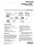
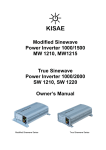
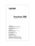
1
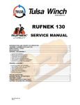
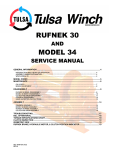
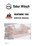
anual
User Ma
Intellig
guard III
This ma
anual MUST be kept with the winch at all times. New winch operators MUST
read and
d understand the co
ontents fully.
INTRODUCTION
The torque induced within the winch drive train is
measured by a torque sensing unit and relayed to the
capacity indicator & the data logger as a ‘percentage of
allowed torque’. The data logger will only record torque
instances that are greater than 80% of the rated torque
capacity of the winch. System events such as power on,
power off, clutch disengage and clutch engage are also
recorded. For more information contact us by mail at
11135 S. James, Jenks, OK 74037. Call (918) 298-8300
or fax us at (918) 298-8367. You may also go to our Web
site at www.team-twg.com.
TABLE OF CONTENTS
INTELLIGUARD II KIT
3 INSTALLATION STEPS
4 CAPACITY INDICATOR REALTIME DISPLAY
6 DOWNLOADING FROM THE DATALOGGER
8 CAPACITY INDICATOR FILE NAMING
10 EVENT RECORDS
11 RAW DATA LOG FILE
13 SUMMARY REPORT FILE
14 ERROR HANDLING AND TROUBLESHOOTING
15 TULSA WINCH LIMITED WARRANTY
16 3
INTELLIGUARD II KIT
Capacity
Indicator
Power supply connects
to vehicle ignition
system
(12v)
Connects to
clutch position
indicator
(Winch)
Connects to
torque sensor
(Winch)
Sel-0119.docx
Rev0
Data Logger
4
INSTALLATION STEPS
1.
Ensure you have the data logger, wiring harness and
capacity indicator that was calibrated from the factory
for the winch you are installing.
2.
Recognize the length of the cable to connect to the
winch from the data logger and mount the data logger
in the cab accordingly.
3.
Mount the capacity indicator inside the cab located as
to be visible by the operator when operating the
winch. Keep in mind the length of the cable when
locating the capacity indicator.
4.
Route and connect the torque sensor wire from the
data logger to the winch being sure not to coil the
wire.
5.
Connect the two ringed terminals to the clutch
position indicator on the winch.
6.
Connect the power leads (red +) (black -) to a power
source such that the intelliguard system is powered
when the PTO is energized or the ignition switch is in
the on position.
Note: the time at which the
Intelliguard unit is powered on and off is logged and
reported on the data log file and the summary report.
Sel-0119.docx
Rev0
5
1.
Ensure that the data logger, wiring harness, &
capacity indicator are kept with winch. The parts are
calibrated from the factory for a particular winch and
cannot be mixed without re-calibration.
2.
Do not use magnets on or around winches with
Intelliguard.
3.
Before any welding is done disconnect the data
logger, capacity indicator and torque sensor.
4.
When installing Intelliguard the power supply must be
the last thing to connect. Otherwise the system will
invoke an error code indicating one of the
components is malfunctioning or is disconnected.
5.
After the system is fully installed and powered up
check to ensure there are no flashing lights on the
capacity indicator or brain box. If there are flashing
lights contact Tulsa Winch service dep’t for guidance.
Sel-0119.docx
Rev0
6
CAPACITY INDICATOR REALTIME DISPLAY
The Capacity Indicator displays the measured torque
value using five LED’s as follows.
Table 1 Capacity Indicator Realtime LED Display
Torque Load (% of rated
capacity)
0 ≤ Torque ≤ 70%
Capacity Indicator LED Display
Power/Status
% Torque (see above)
71% < Torque ≤ 80%
81% < Torque ≤ 90%
91% < Torque ≤ 100%
101% < Torque ≤ 110%
111% < Torque ≤ 125%
The Capacity Indicator displays its status using the Power
LED, which is a dual-color type. The Power LED will
appear as a static color (red, green, orange) for normal
operation, or will flash when an error occurs in
downloading via the USB connection.
Table 2 Capacity Indicator Status Display
Status
LED Display
Power On
System Initialization
Power/Status % Torque (see above)
Power On
No Torque
Recorded
Power On
Torque
Records Available
Power On
System Error
On USB
Power Off
Sel-0119.docx
Rev0
(Flashing)
7
The Capacity Indicator also displays system erro
ors that
might occur. When
W
a system errror occurs, the LE
ED’s on
the Capacity In
ndicator will start flashing (see chart below),
b
and the Datalo
ogger will log the errors that it can detect
with a correspo
onding error event value.
v
Table 3 Capa
acity Indicator Error Display and Error Event
Values
Errror Event
Value
Error
167
Real Time
T
Clock Stoppe
ed
168
Real Time Clock Batteryy
Low
Invalid Real Time Clockk
Value
Intternal Datalogger
Memory Error
Loss of Communicationss
Be
etween Capacity
Indica
ator and Datalogge
er
Cap
pacity Indicator not
Respo
onsive to Datalogge
er
Commands
Flashing LE
ED Display
Power/Status
169
170
172
173
Capacity Ind
dicator
Sel-0119.docx
Rev0
Error Code
8
DOWNLOADING FROM THE DATALOGGER
When a torque record in the range of interest occurs
(>80% rated capacity) and is available for download, the
Power/Status LED on the Capacity Indicator will change
color to indicate that records are available for
downloading. To download the data, the user must insert
a standard USB memory “stick” in the connector on the
side of the Capacity Indicator and wait for the Capacity
Indicator to generate the Raw Data Log and Summary
Report files on the memory stick.
Progress through the process of downloading will occur as
follows:
1.
Power/Status LED will change from green to
orange (amber) indicating that records of interest
are available for download.
2.
Operator removes dust cap to expose the USB
connector.
3.
Operator inserts standard USB memory stick
(FAT16 or FAT32 format) into the mating
connector.
4.
Power/Status LED will flash rapidly with red color
while recording the Raw Data Log file on the
memory stick.
5.
Power/Status LED will pause for approximately 1
second
6.
Power/Status LED will flash rapidly again with red
color while recording the Summary Report file on
the memory stick.
7.
Power/Status LED will change to green to
indicate successful completion of the recording
process.
OR, Power/Status LED will begin
flashing red color at a slow rate (on/off at 1
second rate) to indicate that an error occurred
during the process.
8.
Operator removes the memory stick from the
Capacity Indicator mating connector.
Sel-0119.docx
Rev0
9
Upon completion of the file recording process, if an error
occurred the Power/Status LED will continue to slowly
flash until the ignition power is cycled off and back on to
reset the Capacity Indicator.
If the Operator attempts to download again after such a
system error, the process will begin again and if
successful the Power/Status LED will change to green, per
the steps described above.
Should the recording of files on the memory stick fail for
any reason (hardware problem, or memory stick is full) the
Power/Status LED may immediately begin to slowly flash
red while the memory stick is first inserted in the Capacity
Indicator.
Sel-0119.docx
Rev0
10
CAPACITY INDICATOR FILE NAMING
The Capacity Indicator generates two files on the memory
stick during the download process. The first file is the
Raw Data Log file, which contains a dump of all the
records contained in the Datalogger memory. The second
file generated is the Summary Report file, which contains
a summary of important torque event ranges, error events,
and statistics regarding operation of the winch system.
After a successful download to the memory stick, the
Capacity Indicator returns to normal operation, and
indicates readiness with the Power/Status LED lit green.
At this time, the Operator may inadvertently insert the
memory stick again, even though the Capacity Indicator is
not indicating the presence of records of interest. This is
allowed because the Capacity Indicator employs a file
naming scheme to avoid losing important data.
The file names are constructed as follows:
“<Serial Number>SUMnnn.txt”
OR
“<Serial Number>LOGnnn.txt”
Where:
“1234567890123456” is the serial number of the
Winch/Intelliguard that was established during
manufacture (or by approved maintenance
personnel at a later date),
“SUM” indicates the Summary Report file
“LOG” indicates the Raw Data Log file
“nnn” is a number beginning at “001”, ranging
through “999”
“.txt” is the file extension indicating that it is a
conventional text file
Sel-0119.docx
Rev0
11
EVENT RECORDS
Event records are presented in the Raw Data Log file in
the following format:
*MM/DD/YY hh.mm.ss nnn t
Where:
“MM/DD/YY” is the event date (month, day and year)
“hh.mm.ss” is the event time (hour, minute and seconds)
“nnn” is the event or torque value, in the maximum range
of 0..255
“t” is the event type, either “S” for System Event or “T” for
Torque Event
System Events are those recorded events that indicate a
change in system status, or the change of an input (i.e.,
clutch switch), or a system error that has occurred since
the last download. The system events are recorded with
the “S” flag at the end of the record, and are defined in the
chart below:
Table 4 System Event Values and Descriptions
Event Value
Description
0
Memory Cleared by Administrator
1
Power Up
2
Power Down
3
Technician Logging on
4
Technician Logged off
5
Administrator Logging on
6
Administrator Logged off
7
Clutch Engaged
8
Clutch Disengaged
9
Serial Number Entered
10
Last Download Date/Time
11
Accumulated Winch Hours
12-166
(undefined – not applicable)
167
Real Time Clock Stopped
168
Real Time Clock Battery Low
169
Invalid Clock Value
170
Datalogger Memory Internal Error
171
(undefined – not applicable)
172
Communications
Lost
Between
Datalogger and Capacity Indicator
173
Bargraph not responsive to Datalogger
Commands
174-255
(undefined – not applicable)
Sel-0119.docx
Rev0
12
Torque Events are those recorded torque values that
either indicate operation of the winch above/below the
minimum torque level (>5%), or near full rated capacity
(>80%).
The beginning of winch usage is defined to be an increase
in measured torque above the minimum level (>5%). But
only the increase above the minimum for the first time will
be recorded in any one winch usage session. When
measured torque subsequently drops below the minimum,
another record will be made to indicate the end of the
winch usage for that session.
Whenever torque is measured above the 80% of rated
capacity level, a record is made. These records are made
consecutively every second or so as long as the measured
torque remains above the 80% level, until measured
torque drops below that level.
Depending on the calibration of the Datalogger’s torque
sensor circuit, the maximum measurable torque is limited
to the performance of the Torque Sensor itself. The
Datalogger cannot differentiate high torque values above
125% of rated capacity. All torque measurements in
excess of 125% will be recorded at the 125% value
Table 5 – Torque Event Values and Descriptions
Torque Value
Description
0-5
First Torque Measured Below
Minimum Usage Level (≤5%)
First Torque Measured Above
Minimum Usage Level (>5%)
Torque Measured in Near-RatedCapacity Range
(Undefined – not applicable)
6-79
80-125
126-255
Sel-0119.docx
Rev0
13
RAW DATA LOG FILE
An example of the Raw Data Log file is shown below:
RUFNEK Intelliguard Detail Report: 02/07/09
SERIAL NUMBER: 009987643
*01/02/09, 06:10:29, 0 S Memory Cleared
Up to five Memory Clear
*01/02/09, 06:10:00, 0 S Memory Cleared
events will be shown.
*01/02/09, 06:10:00, 0 S Memory Cleared
These are never erased.
*01/02/09, 06:10:29, 0 S Memory Cleared
*01/02/09, 06:10:00, 0 S Memory Cleared
*01/02/09, 06:10:00, 11 S Accumulated Hours
Other
*01/02/09, 06:10:00, 10 S Downloaded from Datalogger
special
*01/03/09, 06:10:00, 9 S Serial Number changed
events that
*01/13/09, 12:02:29, 168 S Error: Realtime Clock battery is low
appear in
*01/03/09, 06:11:00, 1 S Power On
the “fixed
*01/03/09, 08:32:01, 51 T
location”
*01/03/09, 09:42:09, 7 S Clutch Engaged
record area
*01/03/09, 09:04:31, 81 T
*01/03/09, 09:05:32, 82 T
*01/03/09, 09:06:33, 83 T
*01/03/09, 09:10:37, 87 T
Beginning of new records
*01/03/09, 09:16:43, 93 T
*01/03/09, 09:17:44, 94 T
*01/03/09, 09:18:45, 95 T
*01/03/09, 09:24:51, 101 T
Torque above minimum,
*01/03/09, 09:25:52, 102 T
start of winch usage
*01/03/09, 09:35:02, 112 T
*01/03/09, 09:40:07, 117 T
*01/03/09, 09:41:08, 118 T
*01/03/09, 09:43:10, 120 T
*01/03/09, 09:44:11, 121 T
*01/04/09, 09:48:15, 125 T
*01/04/09, 09:57:24, 116 T
*01/04/09, 09:59:26, 114 T
Torque near full rated
*01/04/09, 10:03:30, 110 T
capacity, and exceeding
*01/04/09, 10:04:31, 109 T
rated capacity
*01/04/09, 10:05:32, 108 T
*01/04/09, 10:11:38, 102 T
*01/04/09, 10:15:42, 98 T
*01/04/09, 10:16:43, 97 T
*01/04/09, 10:22:49, 91 T
*01/04/09, 10:23:50, 90 T
Torque above minimum,
*01/04/09, 10:27:54, 86 T
start of winch usage
*01/04/09, 10:28:55, 85 T
*01/04/09, 10:29:56, 84 T
*01/04/09, 11:02:29, 0 T
*01/09/09, 12:02:29, 172 S Error: Bargraph disconnected
*02/07/09, 16:44:00, 2 S Power Off
*02/07/09, 16:44:07, 1 S Power On
*02/07/09, 16:44:07, 8 S Clutch Disengaged
A system error occurred
Sel-0119.docx
Rev0
14
SUMMARY REPORT FILE
An example of the summary report file is shown below
RUFNEK Intelliguard Summary Report: 02/07/09
Accumulated Winch Hours: 874.6
Hours Since Last Download: 874.6
Winch Serial Number: 009987643
Accumulated Winch Usage
determined by Datalogger
for torque events >5%
Company:_________________
Vehicle:_________________
Winch #:_________________
Measurements
Date Range
Total Time (Hours)
______________
____________
____________________
Power On Events:
01/03/09-02/07/09
414.9
Winch Usage (>5%): 01/03/09-01/20/09
412.5
Torque Events(>80%): 01/03/09-01/04/09
25.5
Breakdown of winch usage:
Time period that system
was powered since last
download
Time period that winch was
in use at torque > minimum
Time period that torque
exceeded 80% of rated
capacity
Capacity Range Time (Hours) % of Torque Events % of Total Winch Usage
Below 80:
387.0
93.8
93.3
80-89%:
0.3
0.1
0.1
90-99%:
0.3
0.1
0.1
100-109%:
0.3
0.1
0.1
110-119%:
0.3
0.1
0.1
120-125%:
24.2
5.9
5.8
____________________________________________________________________
Totals:
412.5
100.0
99.4
For Clutch Engagement / Disengagement See Detail Report
Error Codes:
01/09/09 172 - Bargraph Heartbeat timed out
PGM: G640300-XX REV: 3.11
Sel-0119.docx
Rev0
Total hours within each torque
range as a percentage of total
winch usage (>5% of rated
capacity)
Total hours within each torque
range as a percentage of total
torque events (>80% of rated
capacity)
Up to 13 errors will be listed
here. “...(more)” means there
were more than 13 system
errors recorded.
15
ERROR HANDLING AND TROUBLESHOOTING
Some errors are transient and may be the result of the
installation process (i.e., Loss of Communications), while
others indicate a system hardware problem that demands
factory servicing.
Table 6 Errors and Their Disposition
Error
167
Disposition
Hardware must be serviced, please call Tulsa Winch Inc.
168
1.
2.
3.
4.
5.
6.
7.
169
1.
2.
3.
4.
5.
6.
7.
8.
Make sure that the cables are securely connected
Connect USB-CAN adapter and run the DataloggerGUI program
Using DataloggerGUI, select the Technician mode and enter PIN
“9707”
Select the Administrator mode as well, and enter PIN “1234”
Click on ‘Clear Errors’ button to clear the error states.
Click on ‘Clear Flash’ to clear the Datalogger memory
Turn off the power supply and retest
If the error persists, please call Tulsa Winch Inc.
Connect USB-CAN adapter and run the DataloggerGUI program
Using DataloggerGUI, select the Technician mode and enter PIN
“9707”
Select the Administrator mode as well, and enter PIN “1234”
Click on ‘Display Time’ to show the current Datalogger time.
If the displayed time is correct, click on ‘Clear Errors’ to clear the
error state and then click on ‘Erase Flash’ to clear the memory.
If the displayed time is not correct, click on ‘Set Clock’ to update the
Datalogger to the current time on the PC
After setting the time, click on ‘Display Time’ to verify that the time
was correctly saved.
Turn off the power supply and retest
If the error persists, please call Tulsa Winch Inc.
170
Hardware must be serviced, please call Tulsa Winch Inc.
172
1.
2.
3.
4.
5.
6.
7.
173
1.
2.
3.
4.
5.
6.
7.
Make sure that the cables are securely connected
Connect USB-CAN adapter and run the DataloggerGUI program
Using DataloggerGUI, select the Technician mode and enter PIN
“9707”
Select the Administrator mode as well, and enter PIN “1234”
Click on ‘Clear Errors’ button to clear the error states.
Click on ‘Clear Flash’ to clear the Datalogger memory
Turn off the power supply and retest
If the error persists, please call Tulsa Winch Inc.
Make sure that the cables are securely connected
Connect USB-CAN adapter and run the DataloggerGUI program
Using DataloggerGUI, select the Technician mode and enter PIN
“9707”
Select the Administrator mode as well, and enter PIN “1234”
Click on ‘Clear Errors’ button to clear the error states.
Click on ‘Clear Flash’ to clear the Datalogger memory
Turn off the power supply and retest If the error persists, please call
Tulsa Winch Inc.
If the error persists, please call Tulsa Winch Inc.
Sel-0119.docx
Rev0
16
TULSA WINCH LIMITED WARRANTY
Effective 1/1/2005
Supersedes All Prior Warranties
Seller warrants that each article sold under this order shall at the time of shipment
(i) conform to applicable specifications, and (ii) be free from defects in material and
workmanship during normal and ordinary use and service (the "Warranty").
Buyer's exclusive remedy and Seller's sole obligation under this Warranty shall be, at
Seller's option, to repair or replace any article or part thereof which has proven to be
defective, or to refund the purchase price of such article or part thereof.
This Warranty shall expire one (1) year from the date the article is first shipped by
Seller. Notice of claimed breach of this Warranty must be given by Buyer to Seller
within the applicable period. Such notice shall include an explanation of the claimed
warranty defect and proof of date of purchase of the article or part thereof for which
warranty coverage is sought. No allowances shall be made by Seller for any
transportation, labor charges, parts, "in and out" costs, adjustments or repairs, or any
other work, unless such items are authorized in writing and in advance by Seller. Nor
shall Seller have any obligation to repair or replace items which by their nature are
expendable.
If an article is claimed to be defective in material or workmanship, or not to conform to
the applicable specifications, Seller will either examine the article at Buyer's site or issue
shipping instructions for return to Seller. This Warranty shall not extend to any articles
or parts thereof which have been installed, used, or serviced otherwise than in
conformity with Seller's applicable specifications, manuals, bulletins, or instructions, or
which shall have been subjected to improper installation, operation, or usage,
misapplication, neglect, overloading, or employment for other than normal and ordinary
use and service.
This Warranty shall not apply to any articles or parts thereof furnished by Seller to
Buyer's specifications and/or furnished by Buyer or acquired from others at Buyer's
request.
SELLER MAKES NO EXPRESS WARRANTIES AND NO IMPLIED WARRANTIES OF
ANY KIND, OTHER THAN THE WARRANTY EXPRESSLY SET FORTH ABOVE.
SUCH WARRANTY IS EXCLUSIVE AND IS MADE AND ACCEPTED IN LIEU OF ANY
AND ALL OTHER WARRANTIES, EXPRESS OR IMPLIED, INCLUDING WITHOUT
LIMITATION THE IMPLIED WARRANTIES OF MERCHANTABILITY AND FITNESS
FOR A PARTICULAR PURPOSE.
The remedies for this Warranty shall be only those expressly set forth above, to the
exclusion of any and all other remedies of whatsoever kind. The limited remedies set
forth above shall be deemed exclusive, even though they may fail their essential
purpose. No agreement varying or extending the foregoing Warranty, remedies,
exclusions, or limitations shall be effective unless in a writing signed by an executive
officer of Seller and Buyer. This Warranty is non transferable.
Under no circumstances shall Seller be liable (i) for any damage or loss to any property
other than the warranted article or part thereof, or (ii) for any special, indirect, incidental,
or consequential damage or loss, even though such expenses, damages, or losses may
be foreseeable.
The foregoing limitations on Seller's liability in the event of breach of warranty shall also
be the absolute limit of Seller's liability in the event of Seller's negligence in
manufacture, installation, or otherwise, with regard to the articles covered by this
Warranty, and at the expiration of the Warranty period as above stated, all such
liabilities shall terminate.
Tulsa Winch, Inc.
P.O. Box 1130
Jenks, OK 74037
Voice: 918-298-8300
Fax: 918-298-8367
Web: www.tulsawinch.com
Email: [email protected]
Sel-0119.docx
Rev0