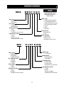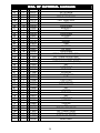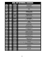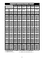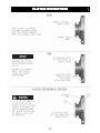
1
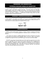
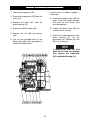
DESIGN SERIES 001
RUFNEK 30
AND
MODEL 34
SERVICE MANUAL
GENERAL INFORMATION .......................................................................................................................... 4
INTRODUCTION AND THEORY OF OPERATION .............................................................................................................4
ASSEMBLY NUMBER EXPLANATION ...............................................................................................................................4
WINCH BREAK-IN ..............................................................................................................................................................4
MODEL CODES ........................................................................................................................................... 5
MAINTENANCE............................................................................................................................................ 6
OIL LEVELS........................................................................................................................................................................7
BRAKE ADJUSTMENT .......................................................................................................................................................8
DISASSEMBLY ............................................................................................................................................ 9
RUFNEK 30 BRAKE DISASSEMBLY..................................................................................................................................9
MODEL 34 BRAKE DISASSEMBLY....................................................................................................................................10
CLUTCH AND DRUM DISASSEMBLY................................................................................................................................11
GEARBOX DISASSEMBLY.................................................................................................................................................12
GEAR INSPECTION INSTRUCTIONS ................................................................................................................................13
ASSEMBLY ................................................................................................................................................ 14
GEARBOX ASSEMBLY ......................................................................................................................................................14
MODEL 34 BRAKE ASSEMBLY..........................................................................................................................................15
RUFNEK 30 BRAKE ASSEMBLY........................................................................................................................................15
CLUTCH AND DRUM ASSEMBLY......................................................................................................................................16
TROUBLESHOOTING................................................................................................................................ 17
BILL OF MATERIAL................................................................................................................................... 18
TORQUE SPECIFICATIONS CHART ........................................................................................................ 19
CLUTCH INSPECTION .............................................................................................................................. 19
ISOMETRIC VIEW ...................................................................................................................................... 19
RUFNEK BRAKE, HYDRAULIC MOTOR, & CLUTCH POSITION INDICATOR...................................... 19
SEL-0046-001.DOC
REV-0
FAILURE TO HEED THE FOLLOWING WARNINGS
MAY RESULT IN SERIOUS INJURY OR DEATH.
The safety of the winch operator and ground personnel should always be of great
concern, and all necessary precautions to insure their safety must be taken. The
primary mover and the winch must be operated with care and concern for the
equipment and the environment and with a thorough knowledge of the equipment and
its performance capabilities must be understood. These general safety guidelines are
offered, however local rules and regulations or national standards may also apply.
Recommended references are, but not limited to, ANSI B30, OSHA 1910, AWS D 14.3,
and SAE J706.
Additional information can be found at http://www.team-twg.com/TulsaWinch/
Indicates an imminently hazardous situation
which, if not avoided, will result in death or serious
injury.
Indicates a potentially hazardous situation which,
if not avoided, could result in death or serious
injury.
Indicates a potentially hazardous situation which,
if not avoided, may result in minor or moderate
injury or property damage.
Indicates information or a company policy that
relates directly or indirectly to the safety of
personnel or protection of property.
Mounting:
Winch mounting must be secure and able to withstand the applied loads.
•
•
•
•
The stability of the mounting system must be approved by a qualified person.
All welding should also be done by a qualified person.
Winch mount must be flat so as not to induce binding.
The flatness must not exceed 1/16 inch across the mounting surface of the winch
itself.
Guards must be placed on all open drives in the case of mechanical winches. Insure
that all hydraulic hoses, valves and fittings are rated to winch manufacturer’s operating
pressures.
Relief valves should be set to winch manufacturer’s specifications. Insure that all PTO’s
and drivelines are sized appropriately for the winch manufactures speed and torque
specifications.
2
Operator:
Must read and understand the operating and service manual.
Both the SERVICE MANUAL and OPERATING AND MAINTENANCE MANUAL
are available online at http://www.team-twg.com/TulsaWinch/
Must never lift or move people with this winch.
This winch is not designed or intended for any use that involves moving people.
Must stay clear of the load at all times.
Ground personnel should remain a safe distance from the load and winch cable
at least 1 ½ times the length of cable measured from the winch to the load.
Must stay clear of the cable at all times.
A broken cable can cause serious injury or death.
Must avoid shock loads.
Shock loads can impose a strain on the winch that can be many times the design
rating.
Must be aware of the fleet angle of the winch.
All loads should only be pulled with the load line perpendicular to the drum shaft,
this is to avoid excessive stresses on the winch and will help prevent the cable
from building on one side of the drum flange.
Must wear personnel protective equipment (PPE) if required.
Check the local, state and federal regulations for compliance.
Must insure that the drum clutch is fully engaged before hoisting.
A visual inspection of the drum clutch engagement is required before each
winching operation.
Must rig all loads secure before winching.
Pull the load line taut and inspect the condition of load for stability.
Must inspect the drum brake if equipped.
The drum brake is not a load holding device it is design to prevent over spooling
of the drum and causing bird nesting of the cable on the drum. Inspect the brake
for wear of the lining and the actuation method.
Must inspect the load control brake.
These winches can be equipped with two (2) forms of dynamic braking. The
worm brake is one method and is adjustable for pay-out load control. Before a
load is handled the load should be pulled tight and stopped to check this brake.
The second method is a hydraulic lowering control that is not field adjustable.
The same method should be used to check this brake.
Operation:
•
•
•
•
•
•
All winch controls must be well marked for function to avoid confusion.
Insure that the PTO is disengaged when the winch is not in use.
All winch controls must be located to provide the operator with a clear view of the
load.
The clutch must be inspected daily for proper operation.
The winch cable should be inspected daily for serviceability.
A minimum of five wraps of tightly wound cable must remain on the drum.
3
GENERAL INFORMATION
INTRODUCTION AND THEORY OF OPERATION
The Tulsa worm gear winch is operated by turning the input of the worm using a
hydraulic motor or PTO driven sprocket and chain. The winch utilizes the adjustable,
spring applied, multiple disc oil brake that activates only during pay-out to provide
maximum efficiency during pay-in. The torque is transferred from the gearbox through
the drum shaft which is keyed to a mechanically actuated sliding clutch that when
engaged transfers the torque to the drum.
ASSEMBLY NUMBER EXPLANATION
This manual is for design series 001. In the case of a major design change
implementation, a new design series designation number will be issued for the winch. A
new manual will also be created for that specific design series.
ASSEMBLY #
DESIGN
SERIES
69216 001
WINCH BREAKBREAK-IN
Winches, like any other kind of machinery, require a “break-in” to perform well and to
maximize their life. The following guidelines should be used in the break-in of Tulsa
Winches.
Use extreme care when first spooling cable onto the winch. DO NOT run the winch
at high speeds when performing this operation. Make sure that the cable is payed-out in
a straight line (to prevent kinks) and SLOWLY pay-in the winch to install the cable.
DO NOT exceed one half rated load or one half rated line speed for the first thirty
minutes of operation. This will insure that the worm and gear have an opportunity to
wear in properly. Periodically, check the gearbox for temperature rises and allow the
winch to cool down between pulls. Worm gear winches are designed and intended for
intermittent duty application only; using them in extremely long pulls may generate
excessive heat and shorten the life of the winch.
4
MODEL CODES
RN30
WM R F O M X
Motor Type
1. Single Speed Gear Motor
2. Two Speed Gear Motor
3. Single Speed Geroler Motor
4. Two Speed Geroler Motor
5. Piston
6. Vane
X. No Motor
Gear Type
W=Worm
P=Planetary
Drive Type
H=Hydraulic
M=Mechanical
Gearbox Position
L=Left
R=Right
(viewed from rear of truck)
Input Shaft Location
F=Front
R=Rear
X=Does not apply
(viewed from rear of truck)
M34
THE RUFNEK 30 SERIES
WINCHES ARE ONLY
AVAILABLE WITH LEFT
HAND GEARS.
Clutch Device
M=Mechanical
A=Air
Cable Spooling
O=Over Drum
U=Under Drum
(viewed from rear of truck)
S L R F O D CL
Motor Type
CL-CharLynn
Winch Type
M=Mechanical
H=Hydraulic
G=Speed Reducer
No. of Worm Starts
S=Single
D=Double
T=Triple
Worm Angle
L=Left
R=Right
Gearbox Location
L=Left
R=Right
(viewed from rear of truck)
Motor Mount
D=Direct Mount
X=No Motor
Cable Spooling
O=Over Drum
U=Under Drum
(viewed from rear of truck)
Input Shaft Location
F=Front
R=Rear
X=Does not apply
(viewed from rear of truck)
5
MAINTENANCE
Tulsa Winch worm gear winches require regular maintenance to ensure safe and
reliable operation. Regular oil changes with the correct oil for the ambient temperature
conditions and an annual inspection of the wear components are strongly
recommended.
Maintenance Scheduling
The owner is to ensure proper inspection intervals, in compliance with the API RP
2D Section 4, ANSI B30.5, 5-2.3, or ANSI B30.7, 7-2.1, and will review winch usage
categories on a periodic basis. A qualified inspector should perform all maintenance
and inspections.
USE
(HRS PER
MONTH)
0-10
11-50
51+
API RP 2D RECOMMENDED
INSPECTION SCHEDULE
PRE-USE, ANNUAL
PRE-USE, QUARTERLY
PRE-USE, MONTHLY
Oil Maintenance
The oil in the gear and brake section should be changed every 1000 hrs or 6 months of
normal usage.
•
Tulsa Winch recommends that the oil level in the gearbox be checked and
adjusted as part of the pre-use inspection. If the oil level drops frequently or oil
leakage is detected during an inspection, maintenance should be performed to
correct any problems.
GEARBOX OIL CAPACITY = 3 QTS
•
Gearbox oil level inspection is achieved by removing the oil level inspection plug
and visually inspecting the oil level. Minimum oil level is to the bottom of the
threads of the inspection hole. Refer to the chart below for the recommended oil
type and grade for your application.
SAE 140W AGMA 7 EP
MOBIL SHC 626
MOBILUBE HD80W140
All oils must meet MIL-PRF2105E standards. Substitution from a reputable
manufacturer is allowed as long as type and grade are maintained.
6
OIL LEVELS
GEARBOX
FILL/VENT
GEARBOX
OIL LEVEL
GEARBOX
OIL DRAIN
BRAKE
FILL/VENT
BRAKE
OIL DRAIN
BRAKE
OIL LEVEL
7
BRAKE ADJUSTMENT
In general, worm brakes on Tulsa winches should be set to hold the load you are
currently working with. Excessive brake torque will result in excessive heat generation
and brake wear. The best way to insure proper brake adjustment is to pull the cable
tight against the load and stop to ensure the brake holds. If it doesn’t, tighten the brake
slightly and try it again. If the brake doesn’t respond to adjustment the brake must be
serviced.
If the input to the winch is accessible and a torque wrench can be adapted to it, the
brake can be set with a torque wrench. The Model 34 brake is shipped from the factory
pre-set at 70 Ft.-Lbs.
ADJUSTABLE SHOE BRAKE
To tighten the brake, loosen the two capscrews in the slotted holes and rotate the brake
in the direction shown. If the brake needs to be reversed, remove those same two
capscrews, rotate the cam 60 degrees and reinstall the capscrews in the other set of
holes which have just been revealed. After adjustment, be sure to re-tighten the cam
capscrews securely.
ADJUSTABLE MULTIPLE DISC OIL BRAKE
RN30W
This style of brake can be adjusted by turning the hex adjuster counter-clockwise to
increase brake and clockwise to decrease brake. The direction of braking for all multiple
disc brakes can be changed by removing the cam clutch, turning it over, and reinstalling it. For detailed service instructions, contact your Tulsa Winch distributor or the
factory.
If the input to the winch is accessible and a torque wrench can be adapted to it, the
brake can be set with a torque wrench. The RN30W brake is shipped from the factory
pre-set at 70 Ft.-Lbs.
8
DISASSEMBLY
RUFNEK 30 BRAKE DISASSEMBLY
1. Remove the bottom drain plug
(100) to drain oil from brake.
5. Inspect parts as follows, replace if
necessary:
2. Loosen the spring tension inside
the brake by rotating the adjusting
nut (97) clockwise until it stops.
A. Inspect the friction discs (104) for
uneven or excessive wear.
Friction discs should measure no
less than .055-in thick.
B. Inspect the stator plates (103) for
warpage or excessive damage.
Extreme care should be taken
when removing the brake cover.
The cover is spring loaded
against the cover screws.
C. Inspect the spring (105)
damage or discoloration.
3. Evenly remove the capscrews (94)
from the brake cover (96).
for
D. Cam clutch (107) should be free
of debris and have all cams intact.
4. Remove the spring (105). Remove
the brake driver (101) along with
the brake components (93, 103,
104, 106, and 107).
If replacing the cam clutch
(107), take note of the direction
it locks up for reassembly.
E. Check coupler (108) for signs of
pitting, spalling, or excessive
wear.
9
MODEL 34 BRAKE DISASSEMBLY
1. Loosen the capscrews (26).
7. Inspect parts as follows, replace if
necessary:
2. Remove the capscrews (30) from the
cover (87).
A. Inspect the brake shoes (86) for
wear. If the shoe linings are worn
flush with the rivet heads, they
must be replaced.
3. Remove the cover (87) from the
brake housing (31).
4. Remove the brake shoes (86).
B. Inspect the brake drum (83) for
severe wear or scoring.
5. Remove the nut (85) and washer
(84).
C. Check the inside lower part of the
brake housing (31) for the
presence of oil. Replace the seal
(55) if oil is present.
6. Use the two threaded holes in the
brake drum (83) and a gear puller to
remove the brake drum.
If replacing the seal (55), first
drain the oil from the gearbox
then remove the capscrews
(56) and brake housing (31).
10
CLUTCH AND DRUM DISASSEMBLY
1. Remove the rod (44) by removing
the cotter keys (43).
and nuts (24) attaching the brake
band to the frame.
2. Remove the arms (34) by removing
the capscrews (46), nuts (24), and
washers (23) holding the arm in
place.
9. Slide the drum (14) off of the output
shaft (68) using an overhead hoist.
10. Inspect parts as follows, replace if
necessary:
3. Remove the line shafts (35) by
loosening the set screws in the
collars (38) and the setscrews (42) in
the arms (45) & (27).
A. Inspect the bushing (2) in the end
bracket (6) for excessive wear.
B. Inspect the keys (67), sliding
clutch (11), and collar (10) for
damage. See page 22 for clutch
inspection.
4. Remove the capscrews (59), nuts
(63), and washers (62) attaching the
end bracket (6) to the frames (65 &
66).
C. Inspect the brake band (8) and
verify the band and lining is at
least .225-in thick.
5. Remove the end cap (5) by removing
the four capscrews (3), nuts (20),
and washers (19).
D. Inspect the drum bushings (60)
for wear or damage.
6. Remove the end bracket (57), yoke
assembly (items 7, 16, 19, 20, 39,
40, 41) or clutch position indicator
assembly (109), and sliding clutch
(55).
E. Inspect the line shafts & linkage
for excessive damage or wear.
7. Remove the keys (67) and collar (10)
from the shaft (68) by loosening set
screw (9).
8. Remove the brake band assembly
(8) by loosening the nuts on the rod
(21) to remove tension on the spring
(22). Then, remove the cotter key
(32) & pin (33) attaching clevis (28)
to control arm (27). Finally, remove
the capscrews (16), washers (23),
11
GEARBOX
GEARBOX DISASSEMBLY
1. Supporting the end of the shaft (68),
remove the cover (76) by removing
capscrews (46 and 78), nuts (20 and
24), and washers (19 and 23).
5. From the brake end, push the worm
(57) out of the housing (61). If the
brake has not been removed, see
brake disassembly on page 9 or 10.
2. Lift the shaft (68), bushings (69),
keys (70), and gear (assembled
items 71, 72, 73, 74, 75, 80, and 81)
out of the housing (61). Remove the
bushings (69) from the shaft (68).
6. Inspect parts as follows, replace if
necessary::
3. Remove the gear (75) from the
carriers (72) by removing the twelve
capscrews (71), nuts (81), and
washers (80), then pull the carrier
(72) off of the shaft (68). Finally,
remove the spacer (73), carrier (72)
and keys (70).
B. Inspect the gear (75) for
excessive wear or damage. See
page 13 for detailed instructions.
A. Inspect the
damage.
carriers
(72)
C. Inspect the keys (70)
bushings (69) for damage.
for
and
D. Inspect the worm (57) for
excessive wear or signs of heat
checking or cracks.
4. Remove the worm (57) from the
housing (61) by removing either the
motor (116) and motor adapter (112),
or just the end cap (51), depending
on the type of drive.
E. Inspect the bearings (54) and
seals (55) for excessive wear or
damage.
12
GEAR INSPECTION INSTRUCTIONS
LAND
Check gear wear by removing the cover and visually inspecting the bronze gear. If the
gear is worn such that there is no visible land on the throat of the gear between the gear
flanks as shown in picture above the gear should be replaced.
13
ASSEMBLY
GEARBOX
GEARBOX ASSEMBLY
1. Press the bearings (54) onto the
worm (57) then install the worm and
bearings into the housing (61).
4. Slide the carrier (72) over the keys
(70). Install the spacer (73) using
the two pins (74). Slide the gear (75)
and the other carrier (72) onto the
shaft and secure with eighteen
capscrews (71), nuts (81), and
washers (80).
2. For winches driven by a hydraulic
motor:
Press a new oil seal (55) into the
motor adapter (112).
Install the
gasket (52).
Attach the motor
adapter (112) to the housing (61)
with six capscrews (89) using gasket
(52). Install the motor (116) with two
capscrews (114) and washers (115),
using gasket (113).
5. Install the assembled gear onto the
shaft (68). Slide the bushings (69)
on to both ends of the shaft (68).
6. Install the output shaft assembly into
the housing (76).
For winches driven by a PTO
sprocket and chain:
Press a new oil seal (55) into the end
cap (51). Attach the end cap (51) to
the housing (61) with six capscrews
(56) using gasket (52).
7. Install both gaskets (79) onto the
housing. Attach the cover (76) to the
housing (61), using capscrews (46 &
78), nuts (19 & 20), washers (19 &
23), using gaskets (79).
8. Fill the gearbox and brake with the
proper oil. Refer to the maintenance
section of this manual for correct oil
type and amount.
3. Install the keys (58) into the output
shaft (68).
14
MODEL 34 BRAKE ASSEMBLY
1. Press the oil seal (55) into the brake
housing (31).
Attach the brake
housing (31) to the gearbox with six
capscrews (56) using gasket (52).
2. Install the brake drum (83) and key
(82) onto the worm shaft (57).
Secure the brake drum with the nut
(85) using the lock washer (84).
Bend two tabs of the washer (84)
over the flats of the nut (85).
4. Install the brake cover (87), cam
(53), and brake shoes (86) into the
brake housing (31).
3. If removed, reattach the cam (53) to
the brake cover (87) in the
orientation
needed
for
your
application using two capscrews (26)
and washers (29).
5. Secure the brake cover (31) using
four capscrews (30).
6. Adjust the brake using the procedure
on page 8 of this manual.
RUFNEK 30 BRAKE ASSEMBLY
1. Press the oil seal (90) into the brake
housing (91).
Attach the brake
housing to the gearbox with eight
capscrews (89) using gasket (110).
4. Install the spring (105).
5. Install the adjusting nut assembly
(assembled items 97, 98, and 99)
into the brake cover (96) and attach
the brake cover to the housing (91)
with eight evenly installed capscrews
(94).
2. Install the key (92) and coupler (108)
onto the worm. Next, install the
clutch/driver assembly (Items 93,
101, 106, and 107), onto the coupler
(108).
6. Install the drain plug (100) into the
bottom of the brake cover (96).
3. With the retaining ring (93) on the
clutch driver (101). Install the stator
plates (104) and friction discs (103),
as shown below.
7. Fill gearbox and brake with proper
oil. Refer to winch maintenance
section of this manual for oil type and
amounts.
8. Adjust the brake using the procedure
on page 8 of this manual.
15
CLUTCH AND DRUM ASSEMBLY
1. Install bushings (60) into drum (14).
Install the drum (14) onto the output
shaft (68).
3. Install the sliding clutch (11) and end
bracket assembly onto the shaft (68),
lining up the yoke with the grooves in
the sliding clutch (11). Attach the
end bracket to the frame using four
capscrews (59), washers (62), and
nuts (63).
2. Install the collar (10). Tap the keys
(67) into the output shaft.
CLUTCH POSITION INDICATOR ADJUSTMENT
(FOR RUFNEK WINCHES ONLY)
Make sure that the sliding clutch (11) is fully engaged and that the yoke assembly (111)
is not binding on the drum clutch. The lugs of the yoke MUST be centered in the groove
with the clutch fully engaged in order for the clutch position indicator to be properly
adjusted (See FIG-1).
The switch is a normally-open electrical switch that is actuated by disengaging the
clutch which closes the circuit.
With the clutch fully engaged, adjust the switch in until the warning device is activated,
then back-out 1/4 turn to deactivate the warning device.
Tighten the jam nut against the clutch bracket to secure the adjustment.
Test the switch by fully engaging, then disengaging, the clutch. The warning device
should activate while disengaging the clutch pivoting no more than 3°.
FIG.-2
FIG.-1
11
111
NUT
SWITCH
16
TROUBLESHOOTING
FAILURE
Clutch handle won’t latch
Oil leaks from housing
PROBABLE CAUSE
a) Clutch jaws aren’t aligned. Align the
jaws by rotating drum.
b) Damaged yoke or linkage. Replace the
yoke or clutch
a) Seal damaged or worn. Replace the
seal(s).
b) Too much gearbox oil.
oil.
Load drifts
Winch runs too slow
Cable drum won’t free spool
Drain excess
c) Gasket is worn. Replace gasket.
a) The brake is out of adjustment or worn.
Adjust brake until load doesn’t drift.
Replace the parts as required.
a) Low flow rate. Check the flow rate and
increase if necessary.
b) Hydraulic motor worn out. Replace the
motor.
a) Winch not mounted squarely. Check
mounting and confirm that the winch is
mounted on a level surface.
b) Clutch not disengaged. Disengage the
clutch.
Hydraulic fluid leaks from the vent in a) Damaged motor shaft seal. Replace
the gearbox
the seal.
Winch won’t pick up heavy loads.
a) Too much cable on the drum. Use the
snatch block or remove some cable
from the drum.
b) System pressure too low. Increase the
hydraulic system pressure.
c) Winch not broke-in. Run winch at half
of rated load for several pulls.
17
BILL OF MATERIAL
BOM DATED SEPTEMBER 2005
SEQ
QTY
P/N
DESCRIPTION
1
2
3
4
5
6
7
8
9
10
11
12
13
14
15
16
17
18
19
20
21
22
23
24
25
26
27
28
29
30
31
32
33
34
35
36
37
38
39
40
41
3
1
4
5
1
1
1
1
2
2
1
1
6
1
1
5
--8
9
5
1
16
15
1
2
1
1
4
4
1
1
1
2
2
-4
4
1
2
1
20517
32842
20266
21128
20053
20256
20129
1741
20515
20096
20262
23598
20407
23595
21154
20270
--20518
20267
20521
20958
20526
20271
20112
20522
20094
20054
20617
28578
21365
20514
939243
20070
20282
-20193
20230
20264
24724
20116
PIN
BUSHING
CAPSCREW
GREASE ZERK
END CAP
BRACKET
BRACKET
BRAKE BAND ASSEMBLY
SET SCREW
WASHER
SLIDING CLUTCH
DRUM CLUTCH
CAPSCREW
DRUM
U BOLT
CAPSCREW
OMIT
OMIT
LOCKWASHER
NUT
NUT
SPRING
LOCKWASHER
NUT
ROD
CAPSCREW
ARM
CLEVIS
WASHER
CAPSCREW
HOUSING
COTTER PIN
CLEVIS PIN
ARM
SHAFT
OMIT
SET SCREW
COLLAR
YOKE
SNAP RING
PIN
18
BILL OF MATERIAL CONTINUED
SEQ
42
43
44a
44b
45
46
47
48
49
50
51
52
53
54
55
56
57a
57b
57c
57d
58
59
60
61
62
63
64
65
66
67
68
69
70
71
72
73
74
75a
75b
76a
76b
77
QTY
2
2
1
1
1
10
1
4
1
1
1
2
1
2
2
16
1
1
1
1
1
8
2
1
8
8
3
1
1
2
1
2
2
10
2
1
2
1
1
1
1
1
P/N
20737
20474
20111
20113
20072
20276
20284
20105
20278
20092
21542
20118
23875
20303
20281
30205
21641
21640
44068
44070
25393
939262
32840
21556
20520
20274
20286
939269
20293
20098
22443
32839
20574
21157
22438
20569
164056
21643
21642
20127
44030
26799
DESCRIPTION
SET SCREW
COTTER PIN
RIGHT HAND ROD
LEFT HAND ROD
ARM
CAPSCREW
BRACKET
KEY
CAPSCREW
WASHER
CAP
GASKET
CAM
BEARING
OIL SEAL
CAPSCREW
RIGHT HAND WORM (M34)
LEFT HAND WORM (M34)
MECHANICAL WORM (RN30)
HYDRAULIC WORM (RN30)
KEY
CAPSCREW
BUSHING
HOUSING
LOCKWASHER
NUT
PIPE PLUG
LEFT FRAME
RIGHT FRAME
KEY
SHAFT
BUSHING
KEY
CAPSCREW
CARRIER
SPACER
PIN
RIGHT HAND GEAR
LEFT HAND GEAR
MODEL 34 COVER
RUFNEK 30 COVER
BREATHER
19
BILL OF MATERIAL CONTINUED
SEQ
78
79
80
81
82
83
84
85
86
87
88
89
90
91
92
93
94
95
96
97
98
99
100
101
102
103
104
105
106
107
108
109
110
111
112
113
114
115
116
117
QTY
4
2
10
10
1
1
1
1
2
1
1
16
1
1
1
1
8
1
1
1
1
1
2
1
1
6
11
1
1
1
1
1
1
1
1
1
2
2
1
1
P/N
20268
20326
20519
20273
20279
29503
20115
20114
1733
3568
43962
40546
44050
43964
25519
44151
20522
13050
43966
41406
43960
41411
21684
44150
44145
33564
44141
33559
29084
33565
44142
12208
20118
4362
40432
40147
13529
41000
40275
996547
DESCRIPTION
CAPSCREW
GASKET
LOCKWASHER
NUT
KEY
BRAKE DRUM
LOCKWASHER
LOCK NUT
BRAKE SHOE
CAM PLATE
BRAKE HOUSING
CAPSCREW
OIL SEAL
BRAKE HOUSING
KEY
O-RING
CAPSCREW
BREATHER
BRAKE COVER
ADJUSTING NUT
SPRING PLATE
O-RING
PLUG
BRAKE DRIVER
RETAINING RING
FRICTION DISC
STATOR PLATE
SPRING
RETAINING RING
CAM CLUTCH
COUPLER
BUSHING
GASKET
YOKE ASSEMBLY W/ POSITION INDICATOR
MOTOR ADAPTER
GASKET
CAPSCREW
WASHER
MOTOR
OIL SEAL
20
TORQUE SPECIFICATIONS
SPECIFICATIONS CHART
Dry
SAE
Grade 5
Torque
*(FtLbs)
Plated
SAE
Grade 5
Lubricated
SAE
Grade 5
Torque
*(Ft-Lbs)
Torque
*(Ft-Lbs)
Dry
SAE
Grade 8
Torque
*(FtLbs)
Plated Lubricated
SAE
SAE
Grade 8
Grade 8
Torque
Torque
*(Ft*(Ft-Lbs)
Lbs)
Nominal
Size
1/4
20
8
6
5
12
9
7
1/4
28
10
7
6
14
10
8
5/16
18
17
13
10
25
18
15
5/16
24
19
14
11
27
20
16
3/8
16
31
23
19
44
33
26
3/8
24
35
26
21
49
37
30
7/16
14
49
37
30
70
53
42
7/16
20
55
41
33
78
58
47
1/2
13
76
57
45
106
80
64
1/2
20
85
64
51
120
90
72
9/16
12
109
82
65
153
115
92
9/16
18
122
91
73
172
129
103
5/8
11
150
113
90
212
159
127
5/8
18
170
128
102
240
180
144
3/4
10
266
200
160
376
282
226
3/4
16
297
223
178
420
315
252
7/8
9
430
322
258
606
454
364
7/8
14
474
355
284
668
501
401
1
1
8
644
483
386
909
682
545
14
721
541
433
1019
764
611
1-1/8
7
794
596
475
1288
966
772
1-1/8
12
890
668
534
1444
1083
866
1-1/4
1-1/4
7
12
1120
1241
840
930
672
745
1817
2012
1363
1509
1090
1207
T = BOLT TORQUE (LB. FT.)
T = (KWD) / 12
K = TORQUE COEFFICIENT (K = 0.20 DRY
K = 0.15 PLATED
K = 0.12 LUBRICATED)
W = PRELOAD TENSION
D = NOMINAL BOLT SIZE (IN.)
* ALL TORQUE VALUE TOLERANCES ARE ± 5%
21
CLUTCH INSPECTION
22
ISOMETRIC VIEW
FOR RUFNEK BRAKE
AND HYDRAULIC
MOTOR, SEE PAGE 24
23
RUFNEK BRAKE, HYDRAULIC MOTOR, & CLUTCH POSITION INDICATOR
RUFNEK
OIL BRAKE
CLUTCH POSITION
INDICATOR KIT
HYDRAULIC
MOTOR VIEW
24