1
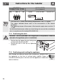
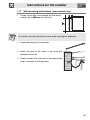
Contents
1.
2.
3.
4.
5.
6.
7.
8.
9.
10.
11.
12.
INSTRUCTIONS FOR USE .............................................................. 54
SAFETY PRECAUTIONS ................................................................. 56
ENVIRONMENTAL CARE................................................................. 58
GET TO KNOW YOUR APPLIANCE ................................................ 59
AVAILABLE ACCESSORIES ............................................................ 62
USING THE COOKING HOB............................................................ 66
USING THE OVEN ........................................................................... 69
OVEN FUNCTIONS .......................................................................... 76
CLEANING AND MAINTENANCE.................................................... 84
EXTRAORDINARY MAINTENANCE ................................................ 90
INSTALLING THE APPLIANCE ........................................................ 92
ADAPTATION TO DIFFERENT TYPES OF GAS........................... 100
INSTRUCTIONS FOR THE USER: these contain user advice, the
description of the controls and the correct procedures for cleaning and
maintenance of the appliance.
INSTRUCTIONS FOR THE INSTALLER: these are intended for the qualified
technician who must install the appliance, set it functioning and carry out
an inspection test.
@
Further information about the products can be found at www.smeg.com
53
General instructions
1. INSTRUCTIONS FOR USE
This manual is an integral part of the appliance. It must be kept in its entirety and in an
accessible place for the whole working life of the appliance. We recommend reading this
manual and all information it contains carefully before using the appliance. Installation
must be carried out by qualified personnel in accordance with the standards in force. This
appliance is intended for domestic use and conforms to the EC directives currently in
force. The appliance has been built to carry out the following functions: cooking and
heating up food; all other uses are considered unsuitable.
These instructions are valid only for the destination countries whose identifying symbols
are included on the cover of this manual.
Never obstruct the openings and slots provided for ventilation and heat dispersal; this may
cause malfunctions.
Do not use this appliance for heating rooms.
This appliance is marked according to European directive 2002/96/EC on Waste Electrical
and Electronic Equipment (WEEE).
This directive defines the standards for the collection and recycling of waste electrical and
electronic equipment applicable throughout the European union.
The identification plate with technical data, serial number and brand name is located in an
exposed position either in the drawer (where present) or on the back of the appliance. A
copy of the identification plate is included in the booklet. It should be applied to the
appropriate space on the back of the cover. Do not remove this plate for any reason.
Before the appliance is put into operation, all labels and protective films applied on
external surfaces must be removed.
Do not use metallic sponges or sharp scrapers as they will damage the surface. Use
normal non-abrasive products and a wooden or plastic tool if necessary. Rinse thoroughly
and dry using a soft cloth. Do not allow residues of sugary foods (such as jam) to set
inside the oven. If left to set for too long, they might damage the enamel lining of the oven.
Do not use plastic kitchenware or containers. The high temperatures inside the oven could
melt the plastic, damaging the appliance.
Always check that the control knobs are in the “zero” (off) position when you finish using
the appliance.
54
General instructions
Do not use sealed tins or containers in the appliance. Overpressure may occur inside the
containers during cooking, creating a danger of explosion.
Do not cover the bottom of the oven with aluminium or tin foil sheets during cooking and
do not place pans or trays on it to avoid damage to the enamelled surface.
Never place saucepans with bases which are not perfectly flat and smooth on the hob.
Unstable cookware can lead to scalding.
Do not rest any weight or sit on the open door of the appliance. Excessive weight may
jeopardise its stability.
The appliance becomes very hot during use. Suitable heat-proof gloves should be worn
for all operations.
Do not use the hob if pyrolysis (where present) is taking place inside the oven.
If you intend to go away for a prolonged period of time, close the mains gas tap or the gas
cylinder tap.
Take care that no objects are stuck in the door of the oven.
Do not open the storage compartment (where present) when the oven is on and still hot.
The temperatures inside it may be very high.
If the surfaces are still very hot during cooking, do not pour water directly onto the trays.
The steam could cause severe burns and damage enamelled surfaces.
All cooking operations must take place with the door closed. The dissipation of heat may
cause hazards.
The manufacturer declines all responsibility for damage to persons or things
caused by non-observance of the above prescriptions or by interference with any
part of the appliance or by the use of non-original spare parts.
55
General instructions
2. SAFETY PRECAUTIONS
Consult the installation instructions for safety standards on electrical or gas appliances
and for ventilation functions. In your interests and for your safety the law requires that the
installation and servicing of all electrical and gas appliances be carried out by qualified
personnel in accordance with the standards in force. Our approved installers guarantee a
satisfactory job.
Gas or electrical appliances must always be uninstalled by suitably skilled people.
Before connecting the appliance to the power grid, check the data on the plate against the
data for the grid itself.
If the appliance is installed on a raised platform, secure it using suitable fastening
systems.
Before carrying out installation/maintenance work, make sure that the appliance is
disconnected from the power grid.
If cooking appliances are installed in motor vehicles (for example, camper vans, caravans
etc.), they must only be used when the vehicle is stationary.
Install the appliance so that when opening the drawers or doors of units positioned at the
level of the hob there is no possibility of making contact with pans positioned on top of it.
The plug to be connected to the power supply cable and its socket must be of the same
type and conform to the standards in force. The socket must be accessible after the
appliance has been installed.
Never disconnect the plug by pulling on the cable.
If the power supply cable is damaged, contact the technical assistance centre immediately
and they will replace it.
The appliance must be connected to earth in compliance with electrical system safety
standards.
During use the appliance and its accessible parts become very hot. Take care never to
touch the heating elements. Keep children younger than 8 away from the appliance,
unless under continuous supervision.
Never put inflammable objects in the oven: they could be accidentally ignited and cause
fires.
56
General instructions
The appliance is intended for use by adults. Do not allow children to go near it or play with it.
This appliance may be used by children from the age of 8 and by people of reduced
physical and mental ability or lacking in experience and knowledge, provided they are
supervised or instructed on the safe use of the appliance and if they understand the
associated risks. Do not allow children to play with the appliance. Do not allow
unsupervised children to perform cleaning or maintenance operations.
Never attempt to repair the appliance. All repairs must be carried out by an authorised
technician or at an authorised service centre. The improper use of tools can cause
hazards.
This appliance must not be controlled using an external timer or remote control system.
Be aware of how rapidly the cooking zones heat up. Do not place empty saucepans on the
heat. Danger of overheating.
Fats and oils can catch fire if they overheat. You are therefore recommended not to leave
the appliance unattended while preparing foods containing oils or fats. If fats or oils catch
fire, never put water on them. Place the lid on the saucepan and turn off the cooking zone.
Take care when using additional electrical appliances in the kitchen (e.g. blender, toaster
etc.). Connection cables must not come into contact with hot cooking zones.
Do not use steam jets for cleaning the appliance.
The steam could reach the electronics, damaging them and causing short-circuits.
Do not spray any spray products near the household appliance while it is in operation. Do
not use spray products while the appliance is still hot. The gases contained in spray cans
may catch fire.
The manufacturer declines all responsibility for damage to persons or things
caused by non-observance of the above prescriptions or by interference with any
part of the appliance or by the use of non-original spare parts.
57
Instructions for disposal
3. ENVIRONMENTAL CARE
3.1
Our environmental care
Pursuant to Directives 2002/95/EC, 2002/96/EC and 2003/108/EC relating to
the reduction of the use of hazardous substances in electrical and electronic
appliances, as well as to the disposal of refuse, the crossed out bin symbol on
the appliance indicates that the product, at the end of its working life, must be
collected separately from other refuse. Therefore, the user must consign the
product that has reached the end of its working life to the appropriate selective
collection centres for electrical and electronic refuse, or deliver it back to the
retailer when purchasing an equivalent product, on a one for one basis.
Adequate selective collection for the subsequent forwarding of the
decommissioned product to recycling, treatment and ecologically compatible
disposal contributes to avoiding possible negative effects on the environment
and on health and promotes the recycling of the materials of which the
appliance consists. Illicit disposal of the product by the user will lead to the
application of administrative sanctions.
The product does not contain substances in quantities sufficient to be
considered hazardous to health and the environment, in accordance with
current European directives.
3.2
Your environmental care
Our product's packaging is made of non-polluting materials, therefore
compatible with the environment and recyclable. Please help by disposing of the
packaging correctly. You can obtain the addresses of collection, recycling and
disposal centres from your retailer or from the competent local organisations.
Do not discard the packaging or any part of it, or leave it unattended. It
can constitute a suffocation hazard for children, especially the plastic
bags.
Your old appliance also needs to be disposed of correctly.
Important: hand over your appliance to the local agency authorised for the
collection of electrical appliances no longer in use. Correct disposal enables
intelligent recovery of valuable materials.
Before disposing of your appliance it is important to remove doors and leave
shelves in the same position as for use, to ensure that children cannot
accidentally become trapped inside during play. It is also necessary to cut the
connecting cable to the power grid, removing it along with the plug.
58
Instructions for the user
4. GET TO KNOW YOUR APPLIANCE
Multifunction models
Pyrolytic Model
1 Cooking hob
5 Fan
2 Control panel
6 Oven light
3 Oven seal
7 Storage compartment
4 Door
Frame shelf
59
Instructions for the user
4.1
Description of the controls on the front panel
Multifunction models
Pyrolytic Model
1 Programming clock
The programming clock makes it possible to display the current time or to set a
timer or a programmed cooking operation.
2 Temperature selection knob
The cooking temperature is selected by turning the knob clockwise to the
required setting, between the maximum and the minimum settings.
60
Instructions for the user
3 Thermostat indicator light
(On multifunction models only)
The indicator light comes on to indicate that the oven is heating up. When this
light goes out, the preset heating temperature has been reached. When the light
flashes regularly, it means that the temperature inside the oven is kept steady
on the set level.
(On pyrolytic models only)
When the indicator light is flashing, it indicates that the oven is heating up to the
temperature set using the thermostat knob. Once the oven has reached the
selected temperature, the light stops flashing and remains lit steadily until the
oven is switched off. Moreover, the light switches on when the automatic
cleaning cycle (pyrolysis) starts and remains lit until the cycle is complete.
4 Function selection knob
The oven's various functions are suitable for different cooking modes. After
selecting the required function, set the cooking temperature using the
thermostat knob. For more information on cooking functions, see: “8. OVEN
FUNCTIONS”.
5 Hob burners control knob
To light the flame, press the knob and turn it anti-clockwise to the maximum
flame symbol (
maximum (
knob to the
). To adjust the flame, turn the knob to the zone between the
) and the minimum (
) settings. To turn off the burner, return the
position.
6 Door lock indicator light (on pyrolytic models only)
It switches on when the automatic cleaning cycle (pyrolysis) is activated.
61
Instructions for the user
5. AVAILABLE ACCESSORIES
NOTE: Some models are not provided with all accessories.
WOK reduction: useful when using a wok.
Wide rack: useful for holding cooking
containers. It can be placed on top of a tray for
cooking foods which may drip.
Narrow rack: useful for cooking small sized
food, such as meat. It can be placed on top of a
tray for cooking foods which may drip.
Tray: useful for collecting fat from foods placed
on the rack above. Necessary when using the
rotisserie.
Rotisserie supports:
rotisserie rod.
They
support
the
Rotisserie rod: for cooking chicken and all
foods which require uniform cooking over their
entire surface.
62
Instructions for the user
•
The oven accessories intended to come into contact with food are made of
materials that comply with the provisions of Directive 89/109/EEC, dated 21/
12/88, and of Legislative Decree 108, dated 25/01/92.
•
Accessories available on request: Original supplied and optional
accessories may be ordered from any Authorised Assistance Centre.
Use only original accessories supplied by the manufacturer.
•
5.1
Using the WOK reduction pan stand
The WOK pan stand should be placed on
top of the hob pan stands as shown in the
adjacent figure. Make sure they are stable.
The WOK pan stand should only be used
when cooking with a wok.
5.2
Using the oven racks and trays
The racks and trays are equipped with a
mechanical safety lock which prevents them
from being taken out accidentally. To insert
the rack or tray correctly, check that the lock
is facing downwards (as shown in the figure
at the side).
To remove the rack or tray, lift the front
slightly.
The mechanical lock (or the extension piece
where present) must always face the back
of the oven.
Gently insert racks and trays into the oven until they come to a stop.
63
Instructions for the user
5.3
Using the rotisserie rod
Keep the oven door closed during cooking.
Use the clip forks provided to prepare the rotisserie rod with the food. The clip
forks can be tightened using the fastening screws.
Place the rotisserie supports into the
inserts at the corners of the tray.
The supports should be placed as shown
in the adjacent figure.
Place the rotisserie rod on the supports. Make sure the pins are correctly
positioned on the shaped part of the supports.
64
Instructions for the user
After having prepared the rotisserie rod, place the tray on the first runner (see 4.
GET TO KNOW YOUR APPLIANCE).
Rocking the rotisserie supports, insert the tip of the rotisserie rod into the hole of
the rotisserie motor on the side of the oven.
At the end of cooking, screw on the handle provided so that you can move the
rod with the food on it readily.
Pour a little water in the drip tray to prevent smoke from forming.
Regular flashing of the thermostat indicator light during cooking is normal and
indicates that the temperature inside the oven is being maintained constant.
65
Instructions for the user
6. USING THE COOKING HOB
6.1
General warnings and advice
Before lighting the hob burners, check that the flame-spreader crowns are
correctly in place with their respective burner caps, making sure that the holes 1
in the flame-spreaders are aligned with the plugs 3 and thermocouples 2.
6.2
Lighting the hob burners
All the appliance's control and monitoring devices are located together on the
front panel. The burner controlled by each knob is shown next to the knob. The
appliance is equipped with an electronic lighter. Simply press the knob and turn
it anti-clockwise to the maximum flame symbol until the burner lights. If the
burner does not light in the first 15 seconds, turn the knob to “0” and wait 60
seconds before trying again. After lighting, keep the knob pressed down for a
few seconds to allow the thermocouple to heat up. The burner may go out when
the knob is released: in this case, the thermocouple has not heated up
sufficiently.
Wait a few moments and repeat the operation, keeping the knob pressed for
longer.
If the burners should go out accidentally, a safety device will be tripped, cutting
off the gas supply, even if the gas tap is open. In this case, turn the knob to the
OFF position and wait at least 60 seconds before trying to light the burner again.
66
Instructions for the user
6.3
Practical hints for using the hob burners
For better burner efficiency and to minimise gas consumption:
use pans with lids and of a suitable size for the burner, so that
the flames do not reach up the sides of the pan (see
paragraph “6.4 Cookware diameters”). Once the contents
come to the boil, turn down the flame far enough to ensure
that the liquid does not boil over.
If any liquid does boil over or spill, remove the excess from the hob. To prevent
burns or damage to the hob during cooking, all pans or griddles must be placed
inside the perimeter of the hob. All pans must have smooth, flat bottoms.
If the flame accidentally goes out, turn off the control knob and wait at least 1
minute before trying to re-light the burner.
Take the greatest care when using fats or oils since they may catch fire if
overheated.
67
Instructions for the user
6.4
Cookware diameters
Burner
68
Ø min. (cm)
Ø max. (cm)
1
Auxiliary
12
14
2
Semi-rapid
16
24
3
Rapid
18
26
4
Ultra-rapid
20
26
5
Fish kettle burner
Suitable oval containers
Instructions for the user
7. USING THE OVEN
7.1
Before using the appliance
•
Remove any labels (apart from the technical data plate) from trays, dripping
pans and the cooking compartment.
• Remove any protective film from the outside or inside of the appliance,
including accessories such as trays, dripping pans, the pizza plate or the
base cover.
• Before using the appliance for the first time, remove all accessories from the
oven compartment and wash them as indicated in “9. CLEANING AND
MAINTENANCE”.
Heat the empty appliance to the maximum temperature in order to remove
any manufacturing residues which could affect the food with unpleasant odours.
7.2
Cooling system
The appliance is equipped with a cooling system which comes into operation as
soon as a cooking function starts. The fan causes a steady outflow of air that
exits from the rear of the appliance and which may continue for a brief period of
time even after the appliance has been turned off.
7.3
Storage compartment
The storage compartment is in the bottom of the cooker, underneath the ovens.
To open it, pull on the bottom of the door.
It provides storage space for the appliance’s metal accessories and must not be
used to store flammable materials, cloths, paper etc.
Do not open the storage compartment when the oven is on and still hot. The
temperatures inside it may be very high.
7.4
Internal oven lights
The oven lights switch on by selecting any function.
69
Instructions for the user
7.5
General warnings and advice for use
All cooking operations must be carried out with the door closed. The
dissipation of heat may cause hazards.
During cooking, do not cover the bottom of the oven with aluminium or tin foil
and do not place pans or oven trays on it as this may damage the enamel
coating. If you wish to use greaseproof paper, place it so that it will not interfere
with the hot air circulation inside the oven.
For the best cooking results, we recommend
placing cookware in the centre of the rack.
To prevent any steam in the oven from causing
problems, open the door in two stages: keep it
half open (5 cm approx.) for 4-5 seconds and
then open it fully. If you need to access the
food, always leave the door open for as short a
time as possible to prevent the temperature in
the oven from falling and ruining the food.
To prevent excessive amounts of condensation from forming on the internal
glass, hot food should not be left inside the oven for too long after cooking.
While cooking desserts or vegetables, excessive condensation may form
on the glass. In order to avoid this, open the door very carefully a couple
of times while cooking.
Heat the empty appliance to the maximum temperature in order to remove
any manufacturing residues which could affect the food with unpleasant odours.
70
Instructions for the user
7.6
Analogue programmer (on some models only)
A
Setting knob
B
Cooking symbol window
C
Manual or timed cooking pointer
7.6.1 Setting the time
To set the correct time, press inward and turn knob A clockwise.
Before each programmer setting, activate the required function and
temperature.
7.6.2 Timed cooking
Enable the required function and cooking temperature before setting the
cooking time. Now, pull out knob A and, turning it clockwise, align pointer C with
the hours pointer. Then, to set the cooking time, visible in window B, turn knob
A clockwise.
7.6.3 Cooking start delay
Turn knob A clockwise until 0 appears in window B. Now, pull out knob A and,
turning it clockwise, align pointer C with the time set for cooking start (the
cooking start time cannot exceed 12 hours in relation to the current time). Now,
turn knob A to symbol
for manual cooking, or to the required cooking time
(at the end of the preset time all the oven heating elements will be switched off).
7.6.4 Manual cooking
Turn knob A clockwise until 0 appears in window B. Now, pull out knob A and,
turning it clockwise, align pointer C with the hours pointer.
Then, turn again knob A clockwise until symbol
is displayed on window B.
71
Instructions for the user
7.7
Programming clock
Timer
End of cooking
Time setting and reset
Value decrease
Value increase
The buzzer that sounds at the end of each programming will be made up of 10
buzzes repeated 3 times at intervals of about 1 minute. It can be stopped at any
time by pressing any key.
7.8
Analogue clock operation
7.8.1 Setting the time
When the oven is used for the first time, or after a power supply failure, the
display flashes at regular intervals.
Press the key
to stop the display flashing. Press key
again for 2
seconds; the current time can now be set. Press the value modification keys
or
to increase or decrease the setting by one minute for each pressure.
Press either of the value modification keys to display the current time. Five
seconds after last pressing the key, the clock will start from the set time.
72
Instructions for the user
7.8.2 Timer
This function only activates the buzzer, without
stopping cooking.
•
Press
figure 1;
and the display will light up as shown in
•
Within
5
•
•
or
1)
to set the timer. Each time a key is
pressed, an outer segment representing 1
minute of cooking is lit or switched off (figure
2 shows 1 hour and 10 minutes).
Five seconds after last pressing the key the
countdown begins, at the end of which the buzzer
activates.
The current time can be viewed during the
2)
seconds
press
key
countdown by pressing key
once, press the
key again to return to the timer display.
At the end of the countdown the oven must be stopped manually by
turning the thermostat knob and the function selector knob to 0.
it is not possible to set a cooking time of more than 4 hours.
73
Instructions for the user
7.8.3 Programming
Cooking time: the 2nd key
can be pressed to set the cooking time. Before it
can be set, the thermostat knob must be turned to the required cooking
temperature and the function selector knob to any setting. To set the cooking
time, proceed as follows:
•
Press key
; the pointer will go to position 12
and the adjacent symbol
•
•
Within 5 seconds press key
will flash (Fig. 1).
or
to set the
cooking time: each pressure on
adds 1
minute to the cooking time, and every 12 minutes
a new inside segment will light up (figure 2 shows
a cooking duration of 1 hour);
Once the required time is obtained, cooking will
start about 5 seconds after the last pressure on
or
•
•
•
.
The display will show the current time,
represented by the constantly illuminated
segments, and the minutes left to the end of the
cooking time, represented by the flashing
segments (each flashing segment means 12
minutes of cooking time left).
At the end of the cooking time the timer will switch
the oven heating elements off, the beeps will start
to sound and the numbers on the dial will flash.
The time can also be reset by deleting the
1)
2)
program selected: Press the central key
for 2
seconds to cancel the set time and the oven will
have to be manually switched off if the cooking
operation is in progress.
it is not possible to set a cooking time of more than 12 hours.
74
Instructions for the user
Cooking start: as well as setting a cooking time, the cooking start time can also
be set (with a maximum delay of 12 hours in relation to the current time). To set
the cooking start/end time, proceed as follows:
• Set the cooking time as described in the previous point.
•
Within 5 seconds of last pressing key
or
, press key
again to set
the cooking end time. Symbol
will flash on the display together with the
current time, with the internal segments illuminated to show the end of
•
•
•
•
•
cooking time. Use keys
and
to set the cooking end time.
5 seconds after the last key is pressed, the display will show the current time
and the cooking start and end times, which will be represented by the
illuminated inside segments. The display segments will be constantly
illuminated as long as the current time is not the same as the cooking start
time; as soon as the current time reaches the set starting time, all the inside
segments will start to flash, indicating that the oven has started cooking.
At the end of the cooking time the timer will switch the oven heating
elements off, the buzzer will start to sound and the numbers on the dial will
flash.
To delete the entire set program, hold down the central key
for 2 seconds; if
cooking has already started, the oven will have to be switched off manually.
Here we can see a programming example: the
current time is 7.06 and cooking is programmed
to start at 8.00 and end at 9.00.
At 8 o'clock the inside segments between 8 and 9
will start to flash, while the hours hand will remain
still.
Warning: for the oven to start cooking after the programming procedures
just described, the thermostat and functions switch knob must be
correctly set on the required temperature and function.
7.8.4 Display brightness reduction
To reduce energy consumption in stand-by, briefly press key
display brightness. To restore the normal brightness, press
to reduce the
again.
75
Instructions for the user
8. OVEN FUNCTIONS
STATIC: As the heat comes from above and below at the same
time, this system is particularly suitable for certain types of food.
Traditional cooking, also known as static or thermal radiation
cooking, is suitable for cooking just one dish at a time. Perfect for
all types of roasts, bread and cakes and in any case particularly
suitable for fatty meats such as goose and duck.
FAN-ASSISTED STATIC: The operation of the fan, combined
with traditional cooking, ensures uniform cooking even with
complex recipes. Perfect for biscuits and cakes, even when
simultaneously cooked on several levels.
GRILL: Using only the heat released from the central element,
this function allows to grill small portions of meat and fish for
making kebabs, toasted sandwiches and any type of grilled
vegetable side dishes.
FAN-ASSISTED GRILL: The air produced by the fan softens the
strong heatwave generated by the grill, giving perfect grilling
results even with very thick foods. Perfect for large cuts of meat
(e.g. shin of pork).
FAN-ASSISTED BOTTOM: The combination of the fan with just
the bottom heating element allows cooking to be completed more
rapidly. This system is recommended for finishing off the cooking
of foods which are already well-cooked on the surface, but not
inside, which therefore need a little more heat. Perfect for any type of food.
BOTTOM + FAN-ASSISTED CIRCULAR: Fan-assisted cooking
is combined with the heat coming from the bottom and allows at
the same time to slightly brown food. Perfect for any type of food.
CIRCULAR: The combination of the fan and the circular element
(incorporated in the rear of the oven) enables different foods to
be cooked on several levels, as long as they need the same
temperature and same type of cooking operation. Hot air
circulation ensures instant and uniform distribution of heat. It will
be possible, for instance, to cook fish, vegetables and biscuits
simultaneously (on different levels) without mixing odours and
flavours.
76
Instructions for the user
DEFROSTING: Rapid defrosting is helped by switching on the
fan to ensure uniform distribution of room temperature air inside
the oven.
ECO: indicates which function gives the least energy
consumption. Using the grill and the bottom heating element plus
the fan is particularly suitable for heating up food, as it provides
low energy consumption.
WIDE GRILL: The heat coming from the grill element gives
perfect grilling results, especially for thin and medium thickness
meat and, in combination with the rotisserie (when present), it
allows the food to be browned evenly at the end of cooking.
Perfect for sausages, ribs and bacon. This function enables large
quantities of food, particularly meat, to be grilled evenly.
ROTISSERIE GRILL: The rotisserie works in combination with
the grill element allowing to perfectly brown food.
TURBO: The combination of fan-assisted cooking and traditional
cooking enables different foods to be cooked on several levels
extremely quickly and efficiently, without any transfer of odours
and flavours. Perfect for large volumes that call for intense
cooking.
PYROLYSIS: When this function is set, the oven reaches temperatures of up to
500°C, destroying all the grease which forms on the internal walls.
77
Instructions for the user
8.1
Cooking advice and instructions
8.1.1 General advice
We recommend preheating the oven before putting food in.
•
•
•
For cooking on several levels, we recommend using a fan-assisted function
to achieve uniform cooking at all heights.
In general, it is not possible to shorten cooking times by increasing the
temperature (the food could be well-cooked on the outside and undercooked
on the inside).
While cooking desserts or vegetables, excessive condensation may form on
the glass. In order to avoid this, open the door very carefully a couple of
times while cooking.
8.1.2 Advice for cooking meat
•
•
Cooking times, especially for meat, vary according to the thickness and
quality of the food and to consumer taste.
We recommend using a meat thermometer for meat when roasting it.
Alternatively, simply press on the roast with a spoon: if it is hard, it is ready;
if not, it needs another few minutes cooking.
8.1.3 Advice for cooking desserts and biscuits
•
•
•
•
Use dark metal moulds for desserts: they help to absorb the heat better.
The temperature and the cooking duration depend on the quality and
consistency of the dough.
Check whether the dessert is cooked right through: at the end of the cooking
time, put a toothpick into the highest point of the dessert. If the dough does
not stick to the toothpick, the dessert is cooked.
If the dessert collapses when it comes out of the oven, on the next occasion
reduce the set temperature by about 10°C, selecting a longer cooking time if
necessary.
8.1.4 Advice for defrosting and proving
•
•
•
•
•
•
78
We recommend positioning frozen foods in a lidless container on the first
shelf of the oven.
The food must be defrosted without its wrapping.
Lay out the foodstuffs to be defrosted evenly, not overlapping.
When defrosting meat, we recommend using a rack positioned on the
second runner with the food on it and a tray positioned on the first runner. In
this way, the liquid from the defrosting food drains away from the food.
The most delicate parts can be covered with aluminium foil.
For successful proving, a container of water should be placed in the bottom
of the oven.
Instructions for the user
8.1.5 Advice for cooking with the Grill and the Fan-assisted grill
• Using the Grill function (where present), meat can be grilled even when it is
put into the cold oven; preheating is recommended if you wish to change the
effect of the cooking.
• With the Fan-assisted grill function (where present), however, we
recommend that you preheat the oven before grilling.
• We recommend placing the food at the centre of the rack.
8.2
To save energy
To save energy while using the appliance, the following instructions may be
followed:
• Stop cooking a few minutes before the time normally used. Cooking will
continue for the remaining minutes with the heat which has accumulated
inside the oven.
• Reduce any opening of the door to a minimum to avoid heat dispersal.
• Use the ECO function (where present) for cooking on a single runner.
• Keep the inside of the appliance clean at all times.
79
Instructions for the user
8.3 Cooking tables
TYPES OF FOOD
WEIGHT FUNCTION
FIRST COURSES
LASAGNE
OVEN-BAKED PASTA
3-4 kg
Static
2 kg
Static
MEAT
ROAST VEAL
1.2 kg
Fan-assisted static
PORK LOIN
1.2 kg
Fan-assisted static
PORK SHOULDER
1.2 kg
Turbo
ROAST RABBIT
1.2 kg
Circular
TURKEY BREAST
1.5 kg
Fan-assisted static
ROAST PORK NECK
2 kg
Turbo
1.2 kg
Turbo
PORK SAUSAGES
1.2 kg
Fan-assisted grill
PORK CHOPS
1.2 kg
Grill
HAMBURGERS
0.8 kg
Grill
BACON
0.8 kg
Fan-assisted grill
ROAST CHICKEN
GRILLED MEATS
ROTISSERIE CHICKEN
1-1.2 kg
Rotisserie grill
FISH
SALMON TROUT
80
1.2 Kg
Fan-assisted bottom
Instructions for the user
RUNNER POSITION
FROM BOTTOM
TEMPERATURE
°C
TIME IN MINUTES
1
220 - 230
50 - 60
1
220 - 230
40
2
180 - 190
70 - 80
2
180 - 190
70 - 80
2
180 - 190
90 - 100
2
180 - 190
70 - 80
2
180 - 190
80 - 90
2
180 - 190
190 - 210
2
180 - 190
60 - 70
1ST SURFACE 2ND SURFACE
3
250 - 280
7-9
5-6
4
250 - 280
15
5
4
250 - 280
9
5
3
250 - 280
13
3
2
250 - 280
70 - 80
150 - 160
35 - 40
81
Instructions for the user
TYPES OF FOOD
WEIGHT FUNCTION
PIZZA
1 kg
Pizza
BREAD
1 kg
Circular
FOCACCIA
1 kg
Turbo
RING CAKE
1 kg
Fan-assisted static
FRUIT TART
1 kg
Fan-assisted static
DESSERTS
SHORT PASTRY
0.5 kg
Fan-assisted bottom
JAM TARTS
1.2 kg
Turbo
PARADISE CAKE
1.2 kg
Fan-assisted static
CREAM PUFFS
0.8 kg
Turbo
LIGHT SPONGE CAKE
0.8 kg
Circular
RICE PUDDING
BRIOCHES
1 kg
0.6 kg
Turbo
Circular
BRIOCHES (on multiple runners)
SHORT PASTRY BISCUITS (on multiple
runners)
The times indicated in the following tables do not include the preheating times
and are provided as a guide only.
82
Instructions for the user
RUNNER POSITION
FROM BOTTOM
TEMPERATURE
°C
TIME IN MINUTES
1
250 - 280
6 -10
2
190 - 200
25 -30
2
180 - 190
15 -20
2
160
50 - 60
2
160
30 - 35
2
160 - 170
20 - 25
2
160
20 - 25
2
160
55 - 60
2
150 - 160
40 - 50
2
150 - 160
45 - 50
2
160
40 - 50
2
160
25 - 30
1 and 3
160 - 170
16 - 20
1 and 3
160 - 170
16 - 20
For cooking on multiple runners, we recommend that you use functions
,
and
only, and the 1st and 3rd runners.
83
Instructions for the user
9. CLEANING AND MAINTENANCE
Do not use steam jets to clean the appliance. The steam could reach the
electronics, damaging them and causing short-circuits.
WARNING: For your safety, you are advised to wear protective gloves
while performing any cleaning or extraordinary maintenance.
Do not use cleaning products containing chlorine, ammonia or bleach on steel
parts or parts with metallic finishes on the surface (e.g. anodizing, nickel- or
chromium-plating).
We recommend the use of cleaning products distributed by the manufacturer.
9.1
Cleaning the surfaces
To keep the oven surfaces in good condition, they should be cleaned regularly
after use. Let the appliance cool first.
9.2
Ordinary daily cleaning
To clean and preserve stainless steel surfaces, always use only specific
products that do not contain abrasives or chlorine-based acids.
How to use: pour the product onto a damp cloth and wipe the surface, rinse
thoroughly and dry with a soft cloth or a microfibre cloth.
9.3
Food stains or residues
Do not use metallic sponges or sharp scrapers as they will damage
the surfaces.
Use normal non-abrasive products and a wooden or plastic tool if
necessary. Rinse thoroughly and dry with a soft cloth or a microfibre
cloth.
Do not allow residues of sugary foods (such as jam) to set inside the
oven. If left to set for too long, they might damage the enamel lining of
the oven.
84
Instructions for the user
9.4
Cleaning the cooking hob parts
9.4.1 Pan stands
Remove the pan stands and clean them with lukewarm water and non-abrasive
detergent, making sure to remove any encrustations. Dry them thoroughly and
return them to the hob.
Continuous contact between the pan stands and the flame can cause
modifications to the enamel over time in those parts exposed to heat. This is a
completely natural phenomenon which has no effect on the operation of this
component.
Do no wash these parts in a dishwasher.
9.4.2 Burner caps and flame-spreader crowns
The burner caps and flame-spreader crowns can be
removed for easier cleaning. Wash them in warm water and
non-abrasive detergent making sure to remove any
encrustation, then wait until they are perfectly dry.
Replace the flame-spreader crowns, making sure that they
are correctly in place with their respective burner caps and
ensuring that the holes A in the flame-spreaders are aligned
with the igniters and thermocouples.
Do no wash these parts in a dishwasher.
9.4.3 Igniters and thermocouples
For correct operation, the igniters and thermocouples must
always be perfectly clean. Check them frequently and clean
them with a damp cloth if necessary. Remove any dry
residues with a wooden toothpick or a needle.
Do not use cleaning products containing chlorine, ammonia or bleach on steel
parts or parts with metallic finishes on the surface (e.g. anodizing, nickel- or
chromium-plating).
85
Instructions for the user
9.5
Cleaning the oven
For the best oven upkeep, clean it regularly after having allowed it to cool. Take
out all removable parts.
•
•
Clean the oven racks with warm water and non-abrasive detergent. Rinse
and dry.
For easier cleaning, the door can be removed (see “10.2 Removing the
door”).
The oven should be operated at the maximum heat setting for 15/20 minutes
after use of specific products, to burn off the residues left inside the oven.
When the operation is complete, damp parts should be dried thoroughly.
9.5.1 Removing guide frames
Removing the guide frames enables the sides to be cleaned more easily.
To remove the guide frames:
1 Pull the frame towards the top of the oven
to unhook it from its housing A, then slide
it out of the seats B at the back.
2 When cleaning is complete, repeat the
above procedures to put the guide frames
back in.
9.6
Cleaning the door glazing
The glass in the door should always be kept thoroughly clean. Use absorbent
kitchen roll; remove stubborn dirt with a damp sponge and an ordinary
detergent.
Do not use abrasive or corrosive detergents to clean the oven door glass panels
(e.g. powder products, spot-removers and wire sponges).
Do not use rough or abrasive materials or sharp metal scrapers to clean the
oven's glass doors since they may scratch the surface.
86
Instructions for the user
9.7
Removing the door seal (not on pyrolitic models)
To permit thorough cleaning of the oven, the
door seal may be removed.
There are fasteners on all four sides to attach it
to the edge of the oven. Pull the edges of the
seal outwards to detach the fasteners. The seal
must be replaced when it loses elasticity and
hardens.
9.8
Cleaning the door seal
To keep the seal clean, use a non-abrasive sponge and lukewarm water. The
seal should be soft and flexible (with the exception of pyrolitic models).
In pyrolitic models, the seal may flatten over time and lose its original shape. To
restore it, pinch the seal all the way along its perimeter. This also helps remove
any dirt on the seal.
9.9
Cleaning self-cleaning panels (catalysis cycle)
If the self-cleaning panels are dirty, primarily with small amounts of grease, a
heating cycle can be executed to regenerate them.
Clean the base and the roof liner first with a microfibre cloth soaked in water and
neutral washing up liquid, then rinse thoroughly.
Set a regeneration cycle by selecting a fan-assisted function at the maximum
temperature for one hour.
If the panels are particularly dirty, after the regeneration cycle, remove them
and wash them with neutral washing up liquid. Then rinse and dry them.
Put the panels back in the oven and set a fan-assisted function at a temperature
of 180°C for one hour, in order to ensure that they are thoroughly dry.
We recommend carrying out the self-cleaning panel regeneration cycle every 15
days.
The panel regeneration cycle is a cleaning method suitable for grease residues,
not sugar-based ones.
87
Instructions for the user
9.10 Pyrolysis: automatic oven cleaning
Pyrolysis may be carried out at any time of the day or night (if you wish to
benefit from the lower cost of electricity overnight).
During the first automatic cleaning cycle, unpleasant odours may occur due to
the normal evaporation of oily manufacturing substances. This is an absolutely
normal phenomenon which disappears after the first cleaning cycle.
Before starting the automatic cleaning cycle, make sure that the oven does not
contain any foods or large spills from previous cooking operations.
During the pyrolysis cycle, a door locking device makes it impossible to open
the door.
9.10.1 Before starting the automatic cleaning cycle
Pyrolysis may be carried out at any time of the day or night (if you wish to
benefit from the lower cost of electricity overnight).
•
•
Completely remove all accessories from inside the oven, including the upper
guard.
Remove the guide frames, see “9.5.1 Removing guide frames”.
In order not to damage the internal glass panel, it should be cleaned in
accordance with the usual procedure (see 9.6 Cleaning the door glazing) before
starting the automatic cleaning cycle.
For very stubborn encrustations, lock the door using the pins provided and
remove the glass panel. Spray an oven cleaning product onto the glass (read
the warnings on the product); leave for 60 minutes, then rinse and dry the glass
using kitchen roll or a microfiber cloth. After carrying out these operations,
position the glass panel on the door again and remove the pins locking it.
88
•
Remove the guide frames, see “9.5.1 Removing guide frames”.
•
At the end of the cleaning cycle, when the oven has cooled down, reinsert
the frames by repeating the previously used procedure in reverse order.
•
Make sure that the oven door is firmly closed.
Instructions for the user
Refer to the following diagram for setting the cleaning cycle duration:
CLEANING
DURATION
LIGHT DIRT
MEDIUM DIRT
HEAVY DIRT
120 MIN.
165 MIN.
210 MIN.
During the automatic cleaning cycle, the fans produce a more intense level of
noise due to a greater rotation speed; this is entirely normal and intended to
facilitate heat dissipation.
At the end of pyrolysis, the fans will continue to operate for long enough to avoid
overheating the walls of adjacent units and the front of the oven.
If the pyrolysis gives unsatisfactory results at minimum duration, it is
recommended to set a longer time for successive cleaning cycles.
9.10.2 Setting the cleaning cycle
Turn the function selection knob to
Press and hold down key
to select the cleaning cycle.
; press keys
or
to set the cycle duration.
The setting varies between a minimum of 2 hours and a maximum of 3 hours
and 30 minutes.
Press
to confirm the start of the pyrolysis.
Two minutes after the cleaning cycle (Pyrolysis) starts, a door
locking device will be tripped, preventing the door from being
opened. The appropriate light will switch on to indicate that the
locking device has been activated.
At the end of the cleaning cycle the door locking device will remain active until
the temperature inside the oven has reached a safety threshold. When the oven
has cooled down, collect the residues from automatic cleaning with a damp
microfibre cloth.
To select a cleaning cycle with a delayed start, after setting the duration press
. The time when the cleaning cycle will terminate will appear on the display.
Press and hold down key
, and press keys
or
to set the time at
which you wish to terminate the cleaning cycle.
It is not possible to select any functions once the door locking device has been
activated. Wait for
to go out.
89
Instructions for the user
10.EXTRAORDINARY MAINTENANCE
The oven requires periodic minor maintenance or replacement of parts subject
to wear, such as gaskets, light bulbs, etc. Specific instructions for each
operation of this kind are given below.
Before any intervention that requires access to live parts, disconnect the
appliance from the power supply.
If a problem cannot be resolved through ordinary maintenance or in case of
other types of fault, contact your local technical support centre.
10.1 Replacing the light bulbs
Remove the bulb protector A by turning it
anticlockwise and replace bulb B with a similar
one. Re-fit bulb protector A.
Use only oven bulbs (T 300°C).
90
Instructions for the user
10.2 Removing the door
Open the door completely.
Insert two pins into the holes on the hinges
towards the back of them until they engage.
Grasp the door on both sides with both hands,
lift it forming an angle of around 30° and
remove it.
To reassemble the door, put the hinges in the
relevant slots in the oven, making sure that
grooved sections C are resting completely in
the slots. Lower the door and once it is in place
remove the pins from the holes in the hinges.
91
Instructions for the installer
11.INSTALLING THE APPLIANCE
11.1 Installing in kitchen units
Veneers, adhesives or plastic coatings on adjacent furniture should be
temperature-resistant (no less than 90°C). If they are not sufficiently
temperature-resistant, they may warp over time.
The appliance must be installed by a qualified technician and according to the
regulations in force.
Depending on the type of installation, this appliance belongs to class 2,
subclass 1 (Fig. A - Fig. B) or to class 1 (Fig. C).
It may be installed next to walls, one of which must be higher than the worktop,
at a minimum distance of 50 mm from the side of the appliance, as shown in
figures A and C relative to the installation classes.
Make sure that there is a minimum distance of 750 mm between the stoves of
the hob and any shelf that may be installed directly above it. If a hood is installed
above the hob, refer to the hood instruction manual to ensure the correct
clearance is left.
Built-in appliance (Class 2 subclass 1)
Built-in appliance (Class 2 subclass 1)
Free-standing appliance (Class 1)
92
Instructions for the installer
11.2 Room ventilation and combustion extraction
The room containing the appliance should have a permanent air supply in
accordance with the standards in force. The room where the appliance is
installed must have enough air flow for the regular combustion of gas and for the
air exchange needed in the room itself. The air vents, protected by grills, must
be suitably dimensioned in compliance with current standards and positioned so
that no part of them is obstructed.
The appliance must be kept adequately ventilated in order to eliminate the heat
and humidity produced by cooking: in particular, after prolonged use, you are
recommended to open a window or to increase the speed of any fans.
Combustion products can be extracted by means of hoods connected to a
natural draught chimney whose efficiency is assured or via forced extraction. An
efficient extraction system requires precision planning by a specialist qualified in
this area and must comply with the positions and distances indicated by the
applicable standards. When the job is complete, the installer must issue a
certificate of conformity.
Extraction using a hood.
Extraction without a hood.
Single natural draught chimney.
Single chimney with extractor fan.
Directly outdoors with wall- or
window-mounted extractor fan.
Directly outdoors through wall.
Air
Combustion products
Extractor fan
93
Instructions for the installer
11.3 Gas connection
At the end of the installation, check for any leaks with a soapy solution,
never with a flame.
The tightening torque between connections that incorporate a gasket must be
between 10 and 15 Nm.
After carrying out any operation on the appliance, check that the gas
connections are properly tightened.
If the appliance is fuelled by LPG, use a standards-compliant
pressure regulator and connect to the gas cylinder in accordance with
the standards in force.
Make sure that the feed pressure complies with the values indicated
in table “12.2 Burner and nozzle characteristics table”.
94
Instructions for the installer
11.3.1 Connection with a rubber hose
WARNING: The following instructions are valid solely for Class 1
installations. See fig. C in chapter “11.1 Installing in kitchen units”.
Connection using a rubber hose complying with current standards is only
permitted if the hose can be inspected along its entire length.
The inside diameter of the hose must be 8 mm for LPG GAS and 13 mm for
NATURAL GAS and CITY GAS.
Installation with a standards-compliant rubber hose must be
carried out so that the length of the piping does not exceed 1.5
metres; make sure that the hose does not come into contact with
moving parts and that it is not crushed in any way.
Verify that all following conditions are met:
• the hose is fixed to the hose connection with safety clamps;
• no part of the hose is in contact with hot walls (max. 50°C);
• the hose is not under traction or tension and has no kinks or
twists;
• the hose is not in contact with sharp objects or sharp corners;
• if the hose is not perfectly airtight and leaks gas, do not try to
repair it: verify that the hose is not past its expiry date
(serigraphed on the hose itself).
Make the connection to the gas mains using a rubber
hose whose specifications comply with current
standards (verify that the reference standard is 1
3
2
stamped on the hose).
3
Carefully screw the hose connector 3 to the 5
4
appliance’s gas connector 1 (1/2” thread ISO 228-1), 6
placing the seal 2 between them. The hose connector
4 can also be screwed to the hose connector 3,
depending on the diameter of the gas hose used. After having tightened the
hose connector(s), push the gas hose 6 onto the hose connector and secure it
with the clamp 5 that is compliant with the applicable standard.
95
Instructions for the installer
11.3.2 Connection with a flexible steel hose
WARNING: The following instructions are valid for all types of installation,
see fig. A, B, C in chapter “11.1 Installing in kitchen units”.
Only use standards-compliant continuous wall steel hoses no longer than 2
metres.
This type of installation can be used for both built-in and freestanding appliances.
Make the connection to the gas mains using a continuous wall 1
flexible steel hose whose specifications comply with the
2
applicable standard.
Carefully screw the connector 3 to the appliance’s gas connector
3
1 (1/2” thread ISO 228-1), placing the seal 2 between them.
11.3.3 Connection with a flexible steel hose with conical fitting (where
present)
WARNING: The following instructions are valid for all types of installation,
see fig. A, B, C in chapter “11.1 Installing in kitchen units”.
Only use standards-compliant continuous wall steel hoses no longer than 2
metres.
This type of installation can be used for both built-in and freestanding appliances.
Make the connection to the gas mains using a continuous wall
flexible steel hose whose specifications comply with the
applicable standard.
Carefully screw the connector 3 to the appliance’s gas
connector 1 (½” thread ISO 228-1), placing the seal 2 between
them. Apply insulating material to the thread of the connector 3,
and then tighten the flexible steel hose 4 to the connector 3.
96
1
2
3
4
Instructions for the installer
11.4 Electrical connection
Make sure the voltage and the cross-section of the power supply line match the
specifications indicated on the identification plate positioned on the appliance.
Do not remove this plate for any reason. A copy of the plate is attached to the
instructions.
The appliance must be connected to the power supply by a qualified technician.
Before performing any operations, switch off the power supply to the appliance.
The appliance must be connected to earth in compliance with electrical system
safety standards.
Where the appliance is connected to the power grid via plug and socket, both of
these must be of the same type and connected to the power cable in
accordance with current standards. The socket must be accessible after the
appliance has been built in.
NEVER UNPLUG BY PULLING ON THE CABLE.
Should the earthing wire need replacing it must be longer than the conducting
wires so that, if the plug is torn off the power cable, it is the last to be detached.
Avoid use of adapters and shunts as these could cause overheating and a risk
of burns.
If a fixed connection is being used, fit the power line with an omnipolar circuit
breaker with a contact opening gap equal to or greater than 3 mm, in an easily
accessible position close to the appliance.
The manufacturer declines all responsibility for damage to persons or things
caused by non-observance of the above prescriptions or by interference with
any part of the appliance.
97
Instructions for the installer
POSSIBLE
CONNECTION TYPES
220
-
240 V
1N~
CABLE TYPE
(if not present)
3-pole
3 x 1.5 mm²
H05V2V2-F
•
•
Use H05V2V2-F cables withstanding temperatures of 90°C or higher.
The values indicated above refer to the cross-section of the internal
conductor.
• The tightening torque of the screws of the terminal supply wires must be 1.5
- 2 Nm.
The aforementioned power cables are sized taking into account the coincidence
factor (in compliance with standard EN 60335-2-6).
11.5 Positioning the skirt
WARNING: The skirt provided is an integral part of the product; it must be
fastened to the appliance prior to installation.
•
•
Position the skirt above the top, taking care
to align holes A with holes B.
Secure the skirt to the top by tightening
screws C.
11.6 Positioning and levelling the appliance
After making the electrical and/or gas connections, properly level
the appliance on the floor to ensure better stability. Screw or
unscrew the bottom part of the foot until the appliance is stable and
level on the floor.
98
Instructions for the installer
11.7 Wall mounting instructions (some markets only)
1
Fasten a hook bolt (not supplied) into the wall at
a height (h) of 800 mm from the floor.
The installer must provide the hook bolt when installing the appliance.
2
Attach the snap hook to the chain.
3
Attach the end of the chain to the hook bolt
fastened in the wall.
4
Finally, connect the snap hook to the appropriate
hole on the back of the appliance.
99
Instructions for the installer
12. ADAPTATION TO DIFFERENT TYPES OF GAS
BEFORE PERFORMING ANY OPERATIONS, SWITCH OFF THE POWER
SUPPLY TO THE APPLIANCE.
Appliance set for gas:
NATURAL GAS G20 (2H) 20 mbar pressure
(see label on product)
In case of operation with other types of gas, the burner nozzles must be
changed and the minimum flame adjusted on the gas taps.
To change the nozzles, proceed as described in the following paragraphs.
12.1 Replacing the hob nozzles
1
2
3
4
100
Remove the pan stands, and
remove all burner caps and
flame-spreader
crowns
to
access the burner casings.
Unscrew the nozzles using a 7
mm socket wrench.
Replace the burner nozzles
according to the type of gas to
be used (see 12.2 Burner and
nozzle characteristics table).
Replace the burners in the correct position.
Instructions for the installer
12.2 Burner and nozzle characteristics table
For burner arrangement, see “Instructions for the user - 6.4 Cookware
diameters”.
Burner
1
2
3
4
5
Natural gas – G20 20 mbar
Nozzle diameter
1/100 mm
Reduced capacity
(W)
72
400
500
Auxiliary
1.05
Semi-rapid
1.8
97
Rapid
3.0
115
800
Ultra-rapid
4.2
135 + 75
1900
Fish kettle burner
1.9
94
800
Burner
1
2
3
4
5
Rated
heating
capacity
(kW)
Rated
heating
capacity
(kW)
LPG – G30/G31 28/37 mbar
Nozzle
diameter
1/100 mm
Reduced
capacity
(W)
Capacity
g/h G30
Capacity
g/h G31
Auxiliary
1.05
50
400
76
75
Semi-rapid
1.8
65
500
131
129
Rapid
3.0
85
800
218
215
Ultra-rapid
4.2
91 + 46
1900
305
300
Fish kettle burner
1.9
68
800
138
136
101
Instructions for the installer
12.3 Final operations
After replacing the nozzles, reposition the flame-spreader crowns, the burner
caps and the pan stands.
Following adjustment to a gas other than the one originally set in the factory,
replace the gas setting label fixed to the appliance with the one corresponding
to the new gas. The label is inserted inside the nozzle pack (where present).
12.3.1 Adjusting the minimum setting for natural and city gas
Light the burner and turn it to the minimum position. Extract
the gas tap knob and turn the adjustment screw next to the
tap rod (depending on the model) until the correct minimum
flame is achieved.
Refit the knob and verify that the burner flame is stable (when
turning the knob rapidly from the maximum to the minimum
position the flame must not go out). Repeat the operation on
all the gas taps.
12.3.2 Adjusting the minimum setting for LPG
In order to adjust the minimum setting with LPG, the screw at the side of the tap
rod must be tightened clockwise all the way.
102