1
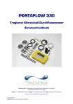
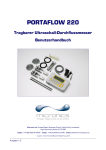
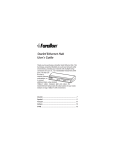
GF Piping Systems User Manual U1000 Ultrasonic Flowmeter Intended use Instruction manual Original instruction manual Follow the instruction manual The instruction manual is part of the product and is an important element of the safety concept. Read and follow the instruction manual. Always keep the instruction manual available at the product. Pass on the instruction manual to all subsequent users of the product. 2 Instruction manual Intended use Contents Original instruction manual ............................................................................................................ 2 Contents ........................................................................................................................................... 3 1 Intended use ..................................................................................................................... 5 2 About this document ........................................................................................................ 5 2.1 Warnings ........................................................................................................................... 5 2.2 Other related documents ................................................................................................. 6 2.3 Abbreviations .................................................................................................................... 6 3 Safety and responsibility .................................................................................................. 6 4 Transport and storage ...................................................................................................... 6 5 Design and function .......................................................................................................... 7 5.1 Design................................................................................................................................ 7 5.2 Principle of operation ....................................................................................................... 7 5.3 Control elements .............................................................................................................. 8 6 Technical specifications ................................................................................................... 9 6.1 Default values ..................................................................................................................11 7 Scope of delivery ..............................................................................................................11 8 Installation .......................................................................................................................12 8.1 Positioning the transducers ............................................................................................12 8.2 Preparation ......................................................................................................................13 8.3 Removing the electronics module from the guide rail ..................................................13 8.4 Adjusting the sensor distance.........................................................................................14 8.5 Mounting the U1000 on the pipe .....................................................................................15 8.5.1 Apply sound-conductive paste ........................................................................................15 8.5.2 Selecting the pipe adapter ..............................................................................................16 8.5.3 Mounting the guide rail ...................................................................................................17 8.5.4 Install the electronics module ........................................................................................17 8.6 Moving the guide rail .......................................................................................................18 8.7 Electrical connection of the U1000 .................................................................................19 9 Startup..............................................................................................................................20 9.1 Preparation ......................................................................................................................20 10 Operation ..........................................................................................................................21 10.1 Entering the pipe inside diameter ..................................................................................21 10.2 Setting the pulse output ..................................................................................................22 10.3 Current output 4 - 20 mA ................................................................................................23 10.4 Switching off and on again ..............................................................................................23 3 Intended use Instruction manual 11 Password-protected menus ...........................................................................................24 11.1 Overview ...........................................................................................................................24 11.2 Opening a password-protected menu ............................................................................24 11.3 Changing the selection menus .......................................................................................25 11.4 Changing the numerical values in data menus .............................................................26 11.5 Password-protected menu structure .............................................................................27 11.5.1 Overview ...........................................................................................................................27 11.5.2 Setup (Einstellungen) ......................................................................................................28 11.5.3 Pulse output (Impulsausgabe) ........................................................................................30 11.5.4 Current output (Stromausgang) .....................................................................................31 11.5.5 Calibration (Kalibrierung)................................................................................................31 11.5.6 Total (Zählwerk) ...............................................................................................................32 11.5.7 Overview of displayed texts in English and German ......................................................33 12 Diagnosis ..........................................................................................................................34 13 Maintenance.....................................................................................................................35 13.1 Maintenance plan ............................................................................................................35 14 Troubleshooting ...............................................................................................................36 15 Removal............................................................................................................................37 16 Disposal ............................................................................................................................37 4 Instruction manual 1 Intended use Intended use The U1000 ultrasound flowmeter is used to obtain an optimal measurement of the volume flow and flow rate in steel and plastic pipes with inside diameter from 20 mm (0.8”) to 115 mm (4.3”). Typical applications Hot water metering and flow measurement Flow measurement and heat measurement Cold water metering and flow measurement Tap water metering and flow measurement Service water metering and flow measurement High-purity water metering and flow measurement 2 About this document This document contains all the information necessary for installation, operation and maintenance of the product. 2.1 Warnings This instruction manual contains warning notices that alert you to the possibility of injuries or damage to property. Always read and pay attention to these warnings! CAUTION WARNING Risk of fatal or serious injury! There is a risk of fatal or serious physical injury if warnings are ignored! CAUTION Danger of minor physical injury! Failure to pay attention to these warnings will lead to a risk of physical injury! NOTICE Risk of damage to property! Failure to comply leads to a risk of damage to property (loss of time, loss of data, device fault etc.)! Other symbols Symbol Meaning 1. Actions required in a numbered sequence. Actions required 5 Safety and responsibility Symbol Meaning Listing of items on various levels Instruction manual • 2.2 Other related documents Georg Fischer industrial planning fundamentals These documents are available through agents of GF Piping Systems or at www.gfps.com. 2.3 Abbreviations Abbreviation Description ABS Acrylonitrile-butadiene-styrene DA Double acting function EMC Electromagnetic Compatibility FC Fail safe to close function FO Fail safe to open function LCD Liquid crystal display LED Light-emitting diode MOSFET Metal oxide semiconductor field effect transistor PB-INSTAFLEX Polybutene plastic piping system PE-ELGEF Polyethylene plastic piping system PP-PROGEF Polypropylene plastic piping system PVDF-SGEF PVDF (polyvinylidene fluoride) plastic piping system SPNO MOSFET Single-pole normally open metal oxide semiconductor field effect transistor VC-U-PVC Polyvinyl chloride 3 Safety and responsibility Only use the product for the intended purpose, see Intended Use. Do not use any damaged or faulty product. Sort out any damaged product immediately. Make sure that the piping system has been installed professionally and that it is inspected regularly. Have the product and accessories installed only by persons who have the required training, knowledge or experience. Regularly train personnel on all questions regarding the locally regulations applying to occupational safety and environmental protection, especially for pressurised pipelines. 4 Transport and storage Protect the product against external forces during transport (impacts, knocks, vibrations etc.). 6 Instruction manual Design and function Transport and / or store the product unopened in its original packaging. Protect the product from dust, dirt, moisture as well as heat and ultraviolet radiation. Ensure that the product is not damaged either by mechanical or thermal influences. Before assembling, check the product for damage during transport. 5 Design and function 5.1 Design 1 Power supply (AC/DC) 4 Guide rail 2 Pipe clamp 5 User interface 3 Electronics module 6 Pipe The U1000 consists of an electronics module (3) and a guide rail (4), which together form a single unit which is fixed to the pipe (6) by pipe clamps (2). The U1000 is supplied with power through an external 12 – 24 V power adapter (1). 5.2 Principle of operation The U1000 takes accurate flow measurements by determining the difference between the transmission times of two ultrasound signals. Principle of operation 7 Design and function Instruction manual A periodic voltage pulse acts on the transducer crystals and produces an ultrasound beam at a certain frequency. The beam is first transmitted by the downstream transducer (blue) to the upstream transducer (red). The beam is then sent in the opposite direction, i.e. from the upstream transducer (red) to the downstream transducer (blue). The time taken for the ultrasound to pass through the liquid in this direction is slightly shortened by the speed at which the liquid flows through the pipe. The resulting time difference T1 – T2 is directly proportional to the speed at which the liquid flows through the pipe. 5.3 Control elements 1 LED 4 - 20 mA is lit when the current output is active 2 LED Pulse is lit when the pulse output is active 3 Button (selection button) switches backwards and forwards through the displayed options 4 Button (reduce value) reduces the value incrementally in the digital input fields 5 Button (increase value) increases the value incrementally in the digital input fields 6 Button (confirm input) confirms the value displayed, ends data input, changes to another menu or the flow values screen 7 LCD display with backlighting (2 rows x 16 characters) 8 Instruction manual 6 Technical specifications Technical specifications Data Kv value Measurement technology Transmission time Measurement channels 1 Resolution of time calculation ± 50 ps Dynamics (turn-down ratio) 200:1 Flow rate 0.1 – 10 m/s Usable liquid types High purity water, clean water with < 3 percent by volume of particle content Accuracy ± 3 % of flow value with a flow rate of > 0.3 m/s Repeatability ± 0.5 % of measured value Selectable units of measurement Flow rate m/s, ft/s Volume flow l/s, l/min, m3/min, m3/hr gal/s, gal/min, USgal/s, USgal/min Volume l, m3, gals, USgals Languages supported English Power input 12 – 24 V (AC or DC) Power consumption 7 VA max. Cable 5 m shielded (6-wire) Pulse output Output Optically insulated MOSFET, volt-free normally open contact Insulation 2,500 V Pulse width Default value 25 ms Programmable range 3 – 99 ms Pulse repeat rate Up to 166 pulses/s (depending on pulse width) Frequency based mode 200 Hz max. Max. voltage/current load 48 V AC / 500 mA Current output Output 4 – 20 mA Resolution 0.1 % of total scale Maximum load 620 Ω Insulation 1,500 V optically insulated Alarm current 3.5 mA 9 Technical specifications Data Instruction manual Kv value Housing Material Polycarbonate Mounting Fixed to the pipe Protection class IP54 Fire classification UL94 V-0 Dimensions 250 mm x 48 mm x 90 mm (electronics module + guide rail) Weight 0.5 kg Ambient conditions Pipe temperature 0 °C to 85 °C Operating temperature (electronics) 0 °C to 50 °C Storage temperature -10 °C to +60 °C Humidity 90% relative humidity at < 50 °C Display LCD 2 rows x 16 characters Viewing angle 30° min., 40° max. Active surface area (W) x (H) 83 mm x 18.6 mm Keypad Format 10 Keypad with 4 buttons Instruction manual 6.1 Scope of delivery Default values The settings are configured at the factory for either metric or British dimensions and weights. Parameters Metric dimensions British dimensions Dimensions mm Inches Volume flow l/min USgal/min Pipe size 50 mm 2“ 4 - 20 mA On On Flow at maximum current Corresponds to 2 m/s Corresponds to 2 m/s Flow at minimum current 0 0 Pulse output On On Volume per pulse 10 l 10 US gallons Pulse width 25 ms 25 ms Damping 20 s 20 s Calibration factor 1.000 1.000 Leak flow rate suppression 0.10 m/s 0.10 m/s Zero offset 0.000 l/min 0.000 gal/min 7 Scope of delivery Component Pcs. U1000 electronics module 1 Guide rail 1 Syringe with sound-conductive paste 1 Pipe clamps 2 Cable 1 Adapter for small pipes < 40 mm 1 Adapter for small pipes < 60 mm 1 11 Installation Instruction manual 8 Installation 8.1 Positioning the transducers The U1000 requires an even and uniform flow profile, since distortions in the flow can cause unpredictable measurement errors. In many applications, however, it is not possible to have a uniform flow rate through 360°. This may be, for example, because there are air bubbles inside the top of the pipe, or turbulence in the pipe, or sludge at the bottom of the pipe. Possible air gap Turbulent flow profile Laminar flow profile Possible deposits (sludge) 10x diameter Possible sensor position 20x diameter Flow Experience has shown that the most accurate results are obtained if the guide rail of the transducers is not mounted vertically to the pipe, but turned at an angle of about 45° to the right or left on the pipe. NOTICE Incorrect measurements Measurements can be distorted if the transducers are positioned close to upstream pipe components and fittings such as pipe bends, T-branches, valves, pumps and similar obstacles. To ensure that the U1000 is positioned at a place that has an undistorted flow profile, the transducers must be mounted sufficiently far from possible sources of distortion to prevent these from having any effect on the measurement. Install a straight section of pipe with length 20 times the diameter on the upstream side of the transducer. In exceptional cases, a pipe with length 10 times the diameter may be sufficient. Install a pipe section with length 10 times the diameter on the downstream side of the transducer. In exceptional cases, a pipe with length 5 times the diameter may be sufficient. 12 Instruction manual 8.2 Installation Preparation Before attaching the transducers, make sure that desired position meets the distance requirements. See Section 8.1 "Positioning the transducers", Page 12. Clean the pipe to remove any grease residues. Remove any dirt and flaking paint in order to ensure an even surface. NOTICE Maximum accuracy A smooth and even contact between pipe surface and transducer is an important factor for obtaining a sufficiently strong ultrasound signal. 8.3 Removing the electronics module from the guide rail Insert a small screwdriver in the opening at one end of the guide rail. Press the screwdriver downward to lever up the clamp connection that holds the electronics module. Repeat the procedure at the other end of the guide rail. 13 Installation 8.4 Instruction manual Adjusting the sensor distance NOTICE Maximum accuracy The two sensors must be placed at defined distance relative to each other, where the distance depends on the pipe diameter and pipe material. Optimal sensor distance Pipe material and pipe diameter Sensor distance PVDF-SGEF, ABS, VC-U-PVC PP-PROGEF PE-ELGEF, PB-INSTAFLEX Steel [mm] [mm] [mm] [mm] B1 25 – 31 25 – 30 25 – 33 – A2 32 – 38 30 – 36 34 – 40 25 – 30 C1 39 – 43 37 – 41 41 – 45 31 – 36 B2 44 – 50 42 – 48 46 – 52 37 – 43 A3 51 – 56 49 – 54 53 – 58 44 – 49 C2 57 – 62 55 – 60 59 – 64 50 – 55 B3 63 – 68 60 – 66 65 – 70 56 – 61 D2 69 – 74 67 – 72 71 – 76 62 – 67 C3 75 – 80 73 – 78 77 – 82 68 – 73 E2 81 – 86 79 – 84 83 – 88 74 – 79 D3 87 – 93 85 – 92 89 – 95 80 – 85 C4 94 – 99 93 – 97 96 – 101 86 – 91 E3 100 – 105 98 – 103 102 – 107 92 – 97 D4 106 – 111 104 – 109 108 – 113 98 – 103 F3 112 – 115 110 – 115 114 – 115 104 – 109 E4 – – – 110 – 115 14 Instruction manual Installation Loosen the sensor mounting screws. Move the sensors to the optimal position (see Table). Tighten the sensor mounting screws. 8.5 Mounting the U1000 on the pipe 8.5.1 Apply sound-conductive paste Using the syringe, apply sound-conductive paste (3) to the sensor contact surfaces (1) and (2). 15 Installation 8.5.2 Instruction manual Selecting the pipe adapter Two adapters are available for attaching the measuring device to pipes with an outside diameter of ≤ 60 mm. NOTICE If these adapters are not necessary, store them away for a possible later change of position. Outside diameter less than 40 mm – top and bottom pipe adapters (black) Outside diameter 40 mm – 60 mm – top pipe adapter (black) Outside diameter more than 60 mm The adapters are placed on the pipe so that the top pipe adapter engages in the end pieces on the guide rail. 16 Instruction manual 8.5.3 Installation Mounting the guide rail Mount the guide rail (1) and pipe adapters if necessary (see Section 8.5.2 "Selecting the pipe adapter ", Page 16) on the pipe (3) using the pipe clamps (2). Loosen the mounting screws and remove along with the washers. NOTICE Store the mounting screws and washers away for future maintenance work or for a possible change of position later. 8.5.4 Install the electronics module Connect the power supply (1) to the electronics module (2). Plug the cables of the two sensors into the sockets (3) and (4) on the electronics module. The cables can be assigned as desired. 17 Installation Instruction manual Set the electronics module (1) on the guide rail (2) and engage it in the clamp connections at both ends. 8.6 Moving the guide rail If it becomes necessary to change the position of the guide rail or the sensors: Loosen the pipe clamps and remove the whole assembly from the pipe. Separate the electronics module from the guide rail. See Section 8.3 "Removing the electronics module from the guide rail", Page 13. Pull the two sensor cables out of the electronics module. Wipe away any residual sound-conductive paste from the sensors using a dry, lint-free cloth. Press the sensors into the guide rail so that the washers and mounting screws can be attached again. Complete the rest of the original installation procedure. See Section 8.5 "Mounting the U1000 on the pipe", Page 15. 18 Instruction manual 8.7 Installation Electrical connection of the U1000 NOTICE The U1000 operates in the voltage range 12 – 24 V (AC/DC). To fully meet the requirements of EMC regulations, a 12 V connection is recommended for domestic and light industrial applications. The U1000 6-wire interface cable 1 12 V / 24 V input (brown) 2 12 V / 24 V return conductor (blue) 3 Pulse + (white) 4 Pulse - (green) 5 Output (+), 4 - 20 mA (red) 6 Return conductor (-), 4 20 mA (black) 7 Non-insulated shielding The SPNO MOSFET relay in the electronics module supplies an insulated switching signal for a switchable current of up to 500 mA and a voltage of up to 48 VAC. This relay also provides 2500 V insulation. Galvanically speaking, it is a volt free output. The 4 - 20 mA current output is an insulated current source designed for loads of < 620 Ω. The alarm current is triggered by flows outside the specified range or by signal loss, and is set at 3.5 mA. WARNING CAUTION Electric shock due to short-current! Before connecting the U1000 to an external power supply, make sure that the power supply is switched off. 19 Startup Instruction manual Connect the external power supply using the brown (1) and blue (2) wires. Connect the pulse output to the system control using the white (3) and green (4) wires. Connect the current output to the system control using the red (5) and black (6) wires. Connect the cable shield (7) to ground. 9 Startup 9.1 Preparation Switch on the U1000 for the first time. The GF start screen is displayed for 5 s. The hundreds digit (050.0) for the pipe inside diameter flashes. Select a pipe inside diameter and a pipe material from the displayed list. See Section 10.1 "Entering the pipe inside diameter", Page 21. The U1000 searches for a valid signal. If a valid signal is detected, the signal strength and flow are displayed. The direction of flow at switch-on time is taken as a positive flow value and the current and pulse output refer to this flow direction. If the flow direction is reversed, the volume flow is still displayed. The activity indicator changes from a star to an exclamation mark, no more pulses are generated and the 4 - 20 mA current output changes to a 3.5 mA alarm status. 20 Instruction manual 10 Operation Operation 10.1 Entering the pipe inside diameter Switch on the U1000 for the first time. The GF start screen is displayed for 5 s. The hundreds digit (050.0) for the pipe inside diameter flashes. Press the button. The flashing hundreds digit (050.0) increases from 0 to 1. Press the button. The flashing hundreds digit (050.0) decreases from 1 to 0. Press the button. The tens digit (050.0) flashes. Press the button. The flashing tens digit (050,0) increases through the number sequence 0, 1, 2, 3, 4, 5, 6, 7, 8, 9 ,0. Press and hold the button. The number sequence scrolls automatically. Press the button. The flashing tens digit (050,0) decreases through the number sequence 9, 8, 7, 6, 5, 4, 3, 2, 1, 0. Press and hold the button. The number sequence scrolls automatically. Press the button. The ones digit (005.0) flashes. Set a value in the same way as for the tens digit. Press the button. The decimal digit (000.5) flashes. Set a value in the same way as for the tens digit. 21 Operation Instruction manual Press the button. The entered value is stored and the next screen is displayed: Press the button. The list of pipe materials scrolls upward. Press and hold the button. The list scrolls automatically. Press the button. The list of pipe materials scrolls downward. Press and hold the button. The list scrolls automatically. Press the button. The selected pipe material is stored and the input procedure ends. If it is necessary to change the preset parameter values (for example, if a different measurement unit is required), then a password must be entered to open the system menu. See Section 11 "Password-protected menus", Page 24. 10.2 Setting the pulse output The pulse output can be set in two different operating modes: Volume based mode After a measured volume of 10 l (preset value), a pulse is sent => 1 pulse/10 l. The maximum number of pulses that can be sent without storing is calculated using the two default parameters Vol per pulse =1 and Pulse width = 25 ms, with the formula 1/(0.025x2) giving a value of 20 pulses/s. If the volume flow in the pipe is so high that more than 20 pulses/s are generated, a pulse overload error may occur if the number of stored pulses exceed a value of 1,000. To avoid this, the Vol per pulse value can be adjusted as necessary. See Section 11 "Password-protected menus", Page 24. Frequency based mode In frequency-based mode, the pulse output frequency is proportional to the volume flow within a frequency range of 0 – 200 Hz. 22 Instruction manual Operation 10.3 Current output 4 - 20 mA The preset output value of 4 - 20 mA is active if the 4 - 20 mA LED is lit. The preset flow value for the 20 mA output is calculated automatically according to the set pipe size. The preset flow value for the 4 mA output is 0. To change this, see Section 11 "Passwordprotected menus", Page 24. If the flow value is greater than the value set for the 20 mA output, or there is negative flow, or a flow signal cannot be detected, then an alarm current of 3.5 mA is generated. NOTICE The 4 – 20 mA current output is pre-calibrated ex works. 10.4 Switching off and on again If the power supply is switched off and then on again after the pipe inside diameter is entered for the first time, then the last applied configuration is used. If the configuration is changed for some reason, the password-protected menu must be used. See Section 11 "Password-protected menus", Page 24. 23 Password-protected menus 11 Instruction manual Password-protected menus 11.1 Overview Password-protected menus allow the preset values to be adapted as required: To change the dimensions from mm to inches or vice versa To change from volume flow to flow rate measurement To change between system units l/m3 or Impgal/USgal To change between flow units l/s, l/min or gal/s, gal/min or USgals/s, USgals/min To change the preset value for flow at maximum current To change the preset value for flow at minimum current To change the type of pulse output To change the pulse output parameters NOTICE The password for the password-protected area is: 71360. 11.2 Opening a password-protected menu Signal strength and the present flow are displayed: Press the button. You are prompted for the password. If the password is not entered, the display automatically changes back to the flow value after a few seconds. Enter the password. See Section 11.4 "Changing the numerical values in data menus", Page 26. Make all the desired changes. Press the button. The current parameter is skipped. Press the button User Menu: Exit. The new values are stored and the password-protected menu is closed. 24 Instruction manual Password-protected menus 11.3 Changing the selection menus NOTICE The procedure for changing the preset values is the same for all menus. Open the password-protected menu. See Section 11.2 "Opening a password-protected menu", Page 24. For example, select the Flow Units parameter. The current value (l/min) flashes Press the button. The value (l/s) flashes. Press the button. The new value (l/s) is stored and the next screen is displayed. 25 Password-protected menus Instruction manual 11.4 Changing the numerical values in data menus NOTICE The procedure for changing numerical values is the same for all menus. In this example, the preset value for the flow at maximum current is changed from 1,000 l to 1,258 l. Open the password-protected menu. See Section 11.2 "Opening a password-protected menu", Page 24. As an example, select the parameter for the flow at maximum current. The thousands digit (1000.0) flashes Press the button twice. The hundreds digit (1000.0) flashes. Press the button twice. The flashing hundreds digit (1000.0) changes to 2. Press the button. The tens digit (1200.0) flashes. Press the button five times. The flashing tens digit (1200.0) changes to 5. Press the button. The ones digit (1250.0) flashes. Press the button twice. The flashing ones digit (1250.0) changes to 8. Press the button. The new value (1258.0) is stored and the next screen is displayed. 26 Instruction manual Password-protected menus 11.5 Password-protected menu structure 11.5.1 Overview Sig: 87 % * 246.3 l/min Invalid input / no input for 10 s Enter Password: ***** See Section 11.5.2 "Setup (Einstellungen)", Page 28. User Menu: Setup User Menu: Pulse Output User Menu: Current Output User Menu: Calibration User Menu: See Section 11.5.3 "Pulse output (Impulsausgabe)", Page 30. See Section 11.5.4 "Current output (Stromausgang)", Page 31. See Section 11.5.5 "Calibration (Kalibrierung)", Page 31. See Section 11.5.6 "Total (Zählwerk)", Page 32. Totals User Menu: Exit Checking Signals ***** Sig: 87% * 246.3 l/min 27 Password-protected menus Instruction manual 11.5.2 Setup (Einstellungen) Metric units Select Dimension: mm | inches Invalid (ungültig) Range 20 – 110 mm inches See British units, Page 29 mm Enter Pipe ID: 050.0 mm 050.0 mm Valid (gültig) & Valid (gültig) Select Reading Flow | Vel Vel Flow System Units: m3 litres | m3 litres (Liter) Flow Units: l/min | l/s Pipe material: PVDF SYGEF Flow Units: m3/min | m3/hr See Section 11.5.1 "Overview", Page 27. 28 Instruction manual Password-protected menus British units Select Dimension: mm | inches Invalid (ungültig) Range 0.79 – 4.33 mm See Metric units, Page 28. inches Enter Pipe ID: 2.000 inches 2.000 inches Valid (gültig) & Valid (gültig) Select Reading Flow | Vel Vel Flow System Units: USgal Impgal | USgal litres (Liter) Flow Units: gal/min | gal/hr Pipe material: PVDF SYGEF Flow Units: USgal/min | USgal/hr See Section 11.5.1 "Overview", Page 27. 29 Password-protected menus Instruction manual 11.5.3 Pulse output (Impulsausgabe) Select Pulse: ON | OFF ON (Ein) & OFF (Aus) Test mode Press the Pulse Type: or button. A pulse is generated VOLUME | FREQ Volume (Volumen) Freq (Frequenz) Max Pulse Freq: Volume per Pulse 200 10.0 l Valid (gültig) Valid (gültig) Invalid (ungültig) Range 1 – 200 200 Valid (gültig) & Invalid (Ungültig) Pulse Width Max Flow @ Freq: 25 ms 9999.0 Valid (gültig) Range 3 – 99 25 ms & Valid (gültig) See Section 11.5.1 "Overview", Page 27. 30 Instruction manual Password-protected menus 11.5.4 Current output (Stromausgang) Select 4-20 mA: ON | OFF & Off (Aus) ON (Ein) Flow @ 20 mA 1000.0 Valid (gültig) Flow @ 4 mA 0000.0 Valid (gültig) See Section 11.5.1 "Overview", Page 27. 11.5.5 Calibration (Kalibrierung) Damping Time [s]: 20 Zero Cut-off: 0.10 m/s To Set (zum Einstellen) Zero Offset: Invalid 0.10 m/s Valid (gültig) Zero Offset Averaging…9 Range 0.00 – 0.50 To clear (zum Löschen) 0.000 l/min Done (gemacht) Calibrat. Factor: 1,000 Invalid Range 0.500 – 1.500 1,000 Valid (gültig) See Section 11.5.1 "Overview", Page 27. 31 Password-protected menus Instruction manual 11.5.6 Total (Zählwerk) Select Totals ON | OFF & OFF (Aus) ON (Ein) Reset + Totals NO | YES See Section 11.5.1 "Overview", Page 27. NOTICE If the totalizer is activated, the display switches back and forth between the flow value and the total. Press the button Each screen is displayed for 30 s. 32 Instruction manual Password-protected menus 11.5.7 Overview of displayed texts in English and German English Deutsch ^ To Clear ^ Zum Löschen Averaging Durchschnittsbestimmung Calibrat. Factor: Kalibrier Faktor: Damping Time (s): Dämpfungszeit (s): Done Abgeschlossen Flow @ 20 mA Durchfluss bei 20 mA Flow @ 4 mA Durchfluss bei 4 mA Freq Frequenz Invalid Ungültig Max Flow @ Freq: Max. Durchfluss bei Freq.: Max Pulse Freq: Max. Impulsfrequenz: NO | YES NEIN | JA OFF AUS ON AN ON | OFF AN | AUS Pulse Type: Impulstyp: Pulse Width Impulsbreite Range Bereich Range 3 – 99 Bereich 3 – 99 Reset + Total: Zurücksetzen + Summe Select 4 – 20 mA: Auswahl 4 – 20 mA: Select Pulse: Auswahl Impuls: Select Totals: Auswahl Summen: v to Set v (Wert verringern oder bestätigen) Valid Gültig Volume Volumen VOLUME | FREQ VOLUMEN | FREQUENZ Volume per Pulse: Volumen pro Impuls Zero Cut-off: Nullsperrung: Zero Offset Nullpunktausgleich 33 Diagnosis 12 Instruction manual Diagnosis NOTICE The diagnosis menu provides additional information and various diagnosis options. In the diagnosis menu, the keypad is less responsive than in normal operating mode. The buttons therefore have to be pressed for a longer time. Sig: 87 % * 246.3 l/min Est. TA 85.64 Act. TA 86.77 Gain 845 (x1) DT 125 ns The estimated transmission time (Est. TA) and actual transmission time (Act. TA) are displayed. There should be a certain ratio between these two values. The gain factor is displayed as an indication of signal strength and switch setting. The values for a good signal 600 – 970 and switch setting (x1). The current time difference (DT) between upstream and downstream signals in [1 ns = 10-9 s]. Rev: 05.00.001 S/N:112547 06/13 124 If the frequency-based option (pulse frequency) is selected, the present pulse output frequency is displayed, proportional to the flow rate. Pipe Material The currently selected pipe material is displayed. Pulse Frequency ABS 34 The software version (Rev.) and serial number (S/N) of the U1000. Instruction manual 13 Maintenance Maintenance CAUTION Risk of injury and loss of product quality through the use of spare parts not provided by GF Piping Systems! Risk of injury and damage to property. If repairs are necessary, please contact your national agent for GF Piping Systems. 13.1 Maintenance plan Set the maintenance intervals according to the operating conditions (e.g. ambient temperature). Carry out the following maintenance tasks as part of the regular system inspection. Maintenance interval Maintenance task 6 – 12 months Renew the sound-conductive paste For questions regarding maintenance of the product, please contact your national GF Piping Systems representative. 35 Troubleshooting 14 Instruction manual Troubleshooting Fault type Error message Cause and remedy System error Poor signal The device is not receiving a signal from one or both transducers. If this message continues to be displayed, replace the sensors. See Section 8.6 "Moving the guide rail", Page 18. Pulse overload The Vol per pulse value is set too low. Increase this value in the passwordprotected menu, see Section 11 "Password-protected menus", Page 24. No BBME This message indicates a device error. Switch the U1000 off then on again. If this message continues to be displayed, please contact the GF Piping Systems Service department. Error Invalid password An invalid password has been entered. Enter the correct password: 71360. Warning messages Range 20 – 110 mm 0.000 mm Range 0 – 99999 0000.0 An invalid pipe inside diameter has been entered. Enter a value within the indicated range. The 4 - 20 mA current output is switched on and, in the password-protected area, an invalid value has been entered for the flow at maximum / minimum current. Enter a value within the indicated range. Range 1 – 200 200 An invalid frequency value has been entered for frequency-based pulse output. Enter a value within the indicated range. Range 3 – 99 00 36 An invalid pulse width value has been entered for volume-based pulse output. Enter a value within the indicated range. Instruction manual Fault type Removal Error message Range 0.000 – 0.500 0000.0 Range 0.000 – 1.500 0000.0 15 Cause and remedy An invalid value has been entered for leak flow rate suppression. Enter a value within the indicated range. An invalid value has been entered for calibration factor. Enter a value within the indicated range. Removal Switch off the external power supply and prevent it from being switched on again. Disconnect all cable connections. Loosen the pipe clamps and remove the U1000 completely from the pipe along with all connecting cables. 16 Disposal Before disposing of the different materials, separate them into recyclable materials, normal waste and special waste. Comply with local legal regulations and provisions when recycling or disposing of the product, individual components and packaging. Comply with national regulations, standards and directives. A product marked with this symbol must be taken to a separate collection point for electrical and electronic devices. If you have any questions regarding disposal of the product, please contact your national agent for GF Piping Systems. 37 Notes GF Piping Systems Worldwide at home Our sales companies and representatives ensure local customer support in over 100 countries. www.gfps.com Argentina / Southern South America Georg Fischer Central Plastics Sudamérica S.R.L. Buenos Aires, Argentina Phone +54 11 4512 02 90 [email protected] www.gfps.com/ar Australia George Fischer Pty Ltd Riverwood NSW 2210 Australia Phone +61 (0) 2 9502 8000 [email protected] www.gfps.com/au Austria Georg Fischer Rohrleitungssysteme GmbH 3130 Herzogenburg Phone +43 (0) 2782 856 43-0 [email protected] www.gfps.com/at Belgium / Luxembourg Georg Fischer NV/SA 1070 Bruxelles/Brüssel Phone +32 (0) 2 556 40 20 [email protected] www.gfps.com/be Brazil Georg Fischer Sist. de Tub. Ltda. 04795-100 São Paulo Phone +55 (0) 11 5525 1311 [email protected] www.gfps.com/br Canada Georg Fischer Piping Systems Ltd Mississauga, ON L5T 2B2 Phone +1 (905) 670 8005 Fax +1 (905) 670 8513 [email protected] www.gfps.com/ca China Georg Fischer Piping Systems Ltd Shanghai 201319 Phone +86 21 3899 3899 [email protected] www.gfps.com/cn Denmark / Iceland Georg Fischer A/S 2630 Taastrup Phone +45 (0) 70 22 19 75 [email protected] www.gfps.com/dk Finland Georg Fischer AB 01510 VANTAA Phone +358 (0) 9 586 58 25 Fax +358 (0) 9 586 58 29 [email protected] www.gfps.com/fi France Georg Fischer SAS 95932 Roissy Charles de Gaulle Cedex Phone +33 (0) 1 41 84 68 84 [email protected] www.gfps.com/fr Germany Georg Fischer GmbH 73095 Albershausen Phone +49 (0) 7161 302-0 [email protected] www.gfps.com/de India Georg Fischer Piping Systems Ltd 400 076 Mumbai Phone +91 224007 2001 [email protected] www.gfps.com/in Indonesia George Fischer Pte Ltd – Representative Office Phone +62 21 2900 8564 Fax +62 21 2900 8566 [email protected] www.gfps.com/sg Italy Georg Fischer S.p.A. 20063 Cernusco S/N (MI) Phone +39 02 921 861 [email protected] www.gfps.com/it Japan Georg Fischer Ltd 556-0011 Osaka, Phone +81 (0) 6 6635 2691 [email protected] www.gfps.com/jp Korea GF Piping Systems Georg Fischer Korea Co., Ltd. Unit 2501, U-Tower 120 HeungdeokJungang-ro (Yeongdeok-dong) Giheung-gu, Yongin-si, Gyeonggi-do, Korea Phone: +82 31 8017 1450 Fax : +82 31 217 1454 [email protected] www.gfps.com/kr Malaysia George Fischer (M) Sdn. Bhd. 40460 Shah Alam, Selangor Darul Ehsan Phone +60 (0) 3 5122 5585 Fax +603 5122 5575 [email protected] www.gfps.com/my Mexico / Northern Latin America Georg Fischer S.A. de C.V. Apodaca, Nuevo Leon CP66636 Mexico Phone +52 (81) 1340 8586 Fax +52 (81) 1522 8906 [email protected] www.gfps.com/mx Singapore George Fischer Pte Ltd 11 Tampines Street 92, #04-01/07 528 872 Singapore Phone +65 6747 0611 Fax +65 6747 0577 [email protected] www.gfps.com/sg Middle East Georg Fischer Piping Systems (Switzerland) Ltd Dubai, United Arab Emirates Phone +971 4 289 49 60 [email protected] www.gfps.com/int Spain / Portugal Georg Fischer S.A. 28046 Madrid Phone +34 (0) 91 781 98 90 [email protected] www.gfps.com/es Netherlands Georg Fischer N.V. 8161 PA Epe Phone +31 (0) 578 678 222 [email protected] www.gfps.com/nl Norway Georg Fischer AS 1351 Rud Phone +47 67 18 29 00 [email protected] www.gfps.com/no Philippines George Fischer Pte Ltd Representative Office Phone +632 571 2365 Fax +632 571 2368 [email protected] www.gfps.com/sg Poland Georg Fischer Sp. z o.o. 05-090 Sekocin Nowy Phone +48 (0) 22 31 31 0 50 [email protected] www.gfps.com/pl Romania Georg Fischer Piping Systems (Switzerland) Ltd 020257 Bucharest - Sector 2 Phone +40 (0) 21 230 53 80 [email protected] www.gfps.com/int Russia Georg Fischer Piping Systems (Switzerland) Ltd Moscow 125047 Phone +7 495 258 60 80 [email protected] www.gfps.com/ru Sweden Georg Fischer AB 117 43 Stockholm Phone +46 (0) 8 506 775 00 [email protected] www.gfps.com/se Switzerland Georg Fischer Rohrleitungssysteme (Schweiz) AG 8201 Schaffhausen Phone +41 (0) 52 631 30 26 [email protected] www.gfps.com/ch Taiwan Georg Fischer Co., Ltd San Chung Dist., New Taipei City Phone +886 2 8512 2822 Fax +886 2 8512 2823 www.gfps.com/tw United Kingdom / Ireland George Fischer Sales Limited Coventry, CV2 2ST Phone +44 (0) 2476 535 535 [email protected] www.gfps.com/uk USA / Caribbean Georg Fischer LLC 9271 Jeronimo Road 92618 Irvine, CA Phone +1 714 731 88 00 Fax +1 714 731 62 01 [email protected] www.gfps.com/us International Georg Fischer Piping Systems (Switzerland) Ltd 8201 Schaffhausen/Switzerland Phone +41 (0) 52 631 30 03 Fax +41 (0) 52 631 28 93 [email protected] www.gfps.com/int The technical data are not binding. They neither constitute expressly warranted characteristics nor guaranteed properties nor a guaranteed durability. They are subject to modification. Our General Terms of Sale apply. GFDO_6384_4 (01.15) © Georg Fischer Piping Systems Ltd CH-8201 Schaffhausen/Switzerland, 2015