1
DLXsim { A Simulator for DLX
Larry B. Hostetler
Brian Mirtich
January 20, 2000
1 Introduction
Our project involved writing a simulator (DLXsim) for the DLX instruction set (as described in Computer
Architecture, A Quantitative Approach by Hennessy and Patterson). DLXsim is an interactive program
that loads DLX assembly programs and simulates the operation of a DLX computer on those programs,
allowing both single-stepping and continuous execution through the DLX code. DLXsim also provides the
user with commands to set breakpoints, view and modify memory and registers, and print statistics on the
execution of the program allowing the user to collect various information on the run-time properties of a
program. We expect that a major use for this tool will be in association with future CS 252 classes to aid
in the understanding of this instruction set.
A complete overview of the interface provided by the simulator can be found in the user manual for
DLXsim, which has been included after this section. Later in this paper, a few sample runs of the simulator
will also be given.
We decided that since the MIPS instruction set has many similarities with DLX, and a good MIPS
simulator (available from Ousterhaut) already exists, it would be a better use of our time to modify that
simulator to handle the DLX description. This simulator was built on top of the Tcl interface, providing a
programming type environment for the user as well.
The main problem we encountered when rewriting the simulator was that there are a couple of fundamental dierences between the DLX and MIPS architectures. Following is a list of the main dierences we
identied between the two architectures.
In MIPS, branch and jump osets are stored as the number of words, where DLX stores the number
of bytes. This has the eect of allowing jumps on MIPS to go four times as far.
MIPS jumps have a non-obvious approach to determining the destination address: the bits in the
oset part of the instruction simply replace the lower bits in the program counter. DLX chooses a
more conventional approach in that the oset is sign extended, and then added to the program counter.
In the MIPS architecture, conditional branches are based on the result of a comparison between any two
registers. DLX has only two main conditional branch operations which branch on whether a register
is zero or non-zero.
DLX provides load interlocks, while the MIPS 2000 does not.
MIPS 2000 provides instructions for unaligned accesses to memory, while DLX does not.
The result of a MIPS multiply or divide ends up in two special registers (HI and LO) allowing 64
bit results; the result of a DLX multiply is placed in the chosen general purpose register, and must
therefore t into 32 bits.
Because of the large number of similarities between DLX and MIPS, we based our opcodes on those
used by the MIPS machine (where MIPS had equivalent instructions). Where DLX had instructions with no
MIPS equivalent, we grouped such similar DLX instructions and assigned to them blocks of unused opcodes.
1
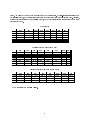
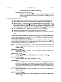
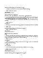
Below, you will nd the opcode numbers used for the DLX instructions. Register-register instructions have
the special opcode, and the instruction is specied in the lower six bits of the instruction word. Similarly,
oating point instructions have the fparith opcode, and the actual instruction is again found in the lower
six bits of the word.
Main opcodes
$00
$01
$02
$03
$04
$05
$06
$07
$00 SPECIAL FPARITH
J
JAL BEQZ BNEZ BFPT BFPF
$08 ADDI
ADDUI SUBI SUBUI ANDI ORI XORI LHI
$10
RFE
TRAP
JR JALR SLLI
SRLI SRAI
$18
SEQI
SNEI
SLTI SGTI SLEI SGEI
$20
LB
LH
LW
LBU LHU
LF
LD
$28
SB
SH
SW
SF
SD
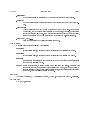
Special opcodes (Main opcode = $00)
$00
$01
$02
$03
$04
$05
$06 $07
$00
SLL
SRL SRA
$08
TRAP
$10
$18
$20 ADD
ADDU
SUB SUBU
AND
OR
XOR
$28
SEQ
SNE
SLT
SGT
SLE
SGE
$30 MOVI2S MOVS2I MOVF MOVD MOVFP2I MOVI2FP
Floating Point opcodes (Main opcode = $01)
$00
$01
$02
$03
$04
$05
$06
$07
$00 ADDF
SUBF MULTF
DIVF
ADDD SUBD MULTD DIVD
$08 CVTF2D CVTF2I CVTD2F CVTD2I CVTI2F CVTI2D MULT DIV
$10
EQF
NEF
LTF
GTF
LEF
GEF MULTU DIVU
$18
EQD
NED
LTD
GTD
LED
GED
The manual entry for DLXsim follows.
2
DLXSIM
User Commands
Page 3
NAME
DLXsim - Simulator and debugger for DLX assembly programs
SYNOPSIS
dlxsim
OPTIONS
[-al#] [-au#] [-dl#] [-du#] [-ml#] [-mu#]
-al# Select the latency for a oating point add (in clocks).
-au# Select the number of oating point add units.
-dl# Select the latency for a oating point divide.
-du# Select the number of oating point divide units.
-ml# Select the latency for a oating point multiply.
-mu# Select the number of oating point multiply units.
DESCRIPTION
DLXsim is an interactive program that loads DLX assembly programs and simulates the operation
of a DLX computer on those programs. When DLXsim starts up, it looks for a le named .dlxsim
in the user's home directory. If such a le exists, DLXsim reads it and processes it as a command
le. DLXsim also checks for a .dlxsim le in the current directory, and executes the commands
in it if the le exists. Finally, DLXsim loops forever reading commands from standard input and
printing results on standard output.
NUMBERS
Whenever DLXsim reads a number, it will accept the number in either decimal notation, hexadecimal notation if the rst two characters of the number are 0x (e.g. 0x3acf), or octal notation if
the rst character is 0 (e.g. 0342). Two DLXsim commands accept only oating pointer numbers
from the user; these are fget and fput and will be described later.
ADDRESS EXPRESSIONS
Many of DLXsim's commands take as input an expression identifying a register or memory
location. Such values are indicated with the term address in the command descriptions below.
Where register names are acceptable, any of the names r0 through r31 and f0 through f31 may
be used. The names $0 through $31 may also be used (instead of r0 through r31), but the dollar
signs are likely to cause confusion with Tcl variables, so it is safer to use r instead of $. The name
pc may be used to refer to the program counter.
Symbolic expressions may be used to specify memory addresses. The simplest form of such an
expression is a number, which is interpreted as a memory address. More generally, address expressions may consist of numbers, symbols (which must be dened in the assembly les currently
loaded), the operators , =, %, +, ,, <<, >>, &, j, and " (which have the same meanings and
precedences as in C), and parentheses for grouping.
COMMANDS
In addition to all of the built-in Tcl commands, DLXsim provides the following application-specic
commands:
asm instruction [address]
Treats instruction as an assembly instruction and returns a hexadecimal value equivalent
DLXSIM
User Commands
Page 4
to instruction. Some instructions, such as relative branches, will be assembled dierently
depending on where in memory the instruction will be stored. The address argument
may be used to indicate where the instruction would be stored; if omitted, it defaults to
0.
fget address [ags]
Return the values of one or more memory locations or registers. Address identies
a memory location or register, and ags, if present, consists of a number and/or set
of letters, all concatenated together. If the number is present, it indicates how many
consecutive values to print (the default is 1). If ag characters are present, they have
the following interpretation:
d
Print values as double precision oating point numbers.
f
Print values as single precision oating point numbers (default).
fput address number [precision]
Store number in the register or memory location given by address. If precision is d, the
number is stored as a double precision oating point number (in two words). If precision
is f or no precision is given, the number is stored as a single precision oating point
number.
get address [ags]
Similar to fget above, this command is for all types except oating point. If ag characters are present, they have the following interpretation:
B
Print values in binary.
b
When printing memory locations, treat each byte as a separate value.
c
Print values as ASCII characters.
d
Print values in decimal.
h
When printing memory locations, treat each halfword as a separate value.
i
Print values as instructions in the DLX assembly language.
s
Print values as null-terminated ASCII strings.
v
Instead of printing the value of the memory location referred to by address,
print the address itself as the value.
w
When printing memory locations, treat each word as a separate value.
x
Print values in hexadecimal (default).
To interpret numbers as single or double precision oating point, use the fget command.
go [address]
Start simulating the DLX machine. If address is given, execution starts at that memory
address. Otherwise, it continues from wherever it left o previously. This command does
not complete until simulated execution stops. The return value is an information string
about why execution stopped and the current state of the machine.
load le le le . . .
Read each of the given les. Treat them as DLX assembly language les and load memory
as indicated in the les. Code (text) is normally loaded starting at address 0x100, but
the codeStart variable may be used to set a dierent starting address. Data is normally
loaded starting at address 0x1000, but a dierent starting address may be specied in
DLXSIM
User Commands
Page 5
the dataStart variable. The return value is either an empty string or an error message
describing problems in reading the les. A list of directives that the loader understands
is in a later section of this manual.
put address number
Store number in the register or memory location given by address. The return value is
an empty string. To store oating point numbers (single or double precision), use the
fput command.
quit Exit the simulator.
stats [reset] [stalls] [opcount] [pending] [branch] [hw] [all]
This command will dump various statistics collected by the simulator on the DLX code
that has been run so far. Any combination of options may be selected. The options and
their results are as follows:
reset Reset all of the statistics.
stalls Show the number of load stalls and stalls while waiting for a oating point
unit to become available or for the result of a previous operation to become
available.
opcount Show the number of each operation that has been executed.
pending Show all oating point operations currently being handled by the oating
point units as well as what their results will be and where they will be stored.
branch Show the percentage of branches taken and not-taken.
hw
Show the current hardware setup for the simulated machine.
all
Equivalent to choosing all options except reset. This is the default.
step [address]
If no address is given, the step command executes a single instruction, continuing from
wherever execution previously stopped. If address is given, then the program counter is
changed to point to address, and a single instruction is executed from there. In either
case, the return value is an information string about the state of the machine after the
single instruction has been executed.
stop [option args]
This command may take any of the forms described below:
stop Arrange for execution of DLX code to stop as soon as possible. If a simulation
isn't in progress then this command has no eect. This command is most often
used in the command argument for the stop at command. Returns an empty
string.
stop at address [command]
Arrange for command (a DLXsim command string) to be executed whenever
the memory address identied by address is read, written, or executed. If
command is not given, it defaults to stop, so that execution stops whenever
address is accessed. A stop applies to the entire word containing address: the
stop will be triggered whenever any byte of the word is accessed. Stops are
not processed during the step commands or the rst instruction executed in
a go command. Returns an empty string.
stop info
DLXSIM
User Commands
Page 6
Return information about all stops currently set.
stop delete number number number . . .
Delete each of the stops identied by the number arguments. Each number
should be an identifying number for a stop, as printed by stop info. Returns
an empty string.
ASSEMBLY FILE FORMAT
The assembler built into DLXsim, invoked using the load command, accepts standard format
DLX assembly language programs. The le is expected to contain lines of the following form:
Labels are dened by a group of non-blank characters starting with either a letter, an underscore, or a dollar sign, and followed immediately by a colon. They are associated with the
next address to which code in the le will be stored. Labels can be accessed anywhere else
within that le, and in les loaded after that if the label is declared as .global (see below).
Comments are started with a semicolon, and continue to the end of the line.
Constants can be entered either with or without a preceding number sign.
The format of instructions and their operands are as shown in the Computer Architecture
book.
While the assembler is processing an assembly le, the data and instructions it assembles are
placed in memory based on either a text (code) or data pointer. Which pointer is used is selected
not by the type of information, but by whether the most recent directive was .data or .text. The
program initially loads into the text segment.
The assembler supports several directives which aect how it loads the DLX's memory. These
should be entered in the place where you would normally place the instruction and its arguments.
The directives currently supported by DLXsim are:
.align n Cause the next data/code loaded to be at the next higher address with the lower n bits
zeroed (the next closest address greater than or equal to the current address that is a
multiple of 2n,1).
.ascii \string1", \string2", . . .
Store the strings listed on the line in memory as a list of characters. The strings are not
terminated by a 0 byte.
.asciiz \string1", \string2", . . .
Similar to .ascii, except each string is followed by a 0 byte (like C strings).
.byte \byte1", \byte2", . . .
Store the bytes listed on the line sequentially in memory.
.data [address]
Cause the following code and data to be stored in the data area. If an address was
supplied, the data will be loaded starting at that address, otherwise, the last value
for the data pointer will be used. If we were just reading code based on the text (code)
pointer, store that address so that we can continue from there later (on a .text directive).
.double number1, number2, . . .
Store the numbers listed on the line sequentially in memory as double precision oating
point numbers.
.oat number1, number2, . . .
Store the numbers listed on the line sequentially in memory as single precision oating
point numbers.
DLXSIM
User Commands
Page 7
.global label
Make the label available for reference by code found in les loaded after this le.
.space size
Move the current storage pointer forward size bytes (to leave some empty space in memory).
.text [address]
Cause the following code and data to be stored in the text (code) area. If an address
was supplied, the data will be loaded starting at that address, otherwise, the last value
for the text pointer will be used. If we were just reading data based on the data pointer,
store that address so that we can continue from there later (on a .data directive).
.word word1, word2, . . .
Store the words listed on the line sequentially in memory.
VARIABLES
DLXsim uses or sets the following Tcl variables:
codeStart
If this variable exists, it indicates where to start loading code in load commands.
dataStart
If this variable exists, it indicates where to start loading data in load commands.
insCount
DLXsim uses this variable to keep a running count of the total number of instructions
that have been simulated so far.
prompt If this variable exists, it should contain a DLXsim command string. DLXsim will
execute the command in this string before printing each prompt, and use the result as
the prompt string to print. If this variable doesn't exist, or if an error occurs in executing
its contents, then the prompt \(dlxsim)" is used.
SEE ALSO
Computer Architecture, A Quantitative Approach, by John L. Hennessy and David A. Patterson.
KEYWORDS
DLX, debug, simulate
2 Interactive Sessions with DLXsim
To illustrate some of the features of DLXsim, this section describes two interactive sessions using examples
taken from Chapter 6 of Computer Architecture, A Quantitative Approach by Hennessy and Patterson.
The programs used are on page 315 and 317. The ADDD instructions have been replaced with MULTD
instructions, however, to show the eects of a slightly longer latency. Also, TRAP instructions have been
added to terminate execution of the programs when simulating.
2.1 Sample Datale
The examples which follow operate on arrays of numbers. A common datale is used for input to the programs. This datale is named fdata.s and is shown below:
.data 0
.global a
a:
.double 3.14159265358979
.global x
x:
.double 1,2,3,4,5,6,7,8,9,10,11,12,13,14,15,16
.double 17,18,19,20,21,22,23,24,25,26,27
.global xtop
xtop: .double 28
The .data directive species that the data should be loaded in at location 0. The .global directive add
the specied labels to a global symbol table so that other assembly les can access them. The .double
directive stores double precision data to memory.
2.2 First Example
The rst example uses the program at the bottom of page 315 (with the ADDD replaced by MULTD). The
program is shown below.
ld
add
loop: ld
multd
sd
sub
bnez
nop
trap
f2,a
r1,r0,xtop
f0,0(r1)
f4,f0,f2
0(r1),f4
r1,r1,#8
r1,loop
; load stall occurs here
; 4 FP stalls
; branch delay slot
#0
; terminate simulation
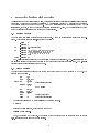
The simulator is invoked by typing dlxsim at the system prompt.
% dlxsim
First the datale is loaded, using the load command:
(dlxsim) load
fdata.s
Next, the program may be loaded. The program above was created with an editor and saved in the le
f1.s. It is loaded in the same way as the datale.
8
(dlxsim) load
f1.s
To verify that the program has been loaded, the get command can be used to examine memory. The
program is loaded at location 256 by default. The second parameter to get indicates how many words to
dump. The i sux tells get to dump the contents in instruction format (i.e. produce a disassembly).
(dlxsim) get
256 9i
start: ld f2,a(r0)
start+0x4: addi r1,r0,0xe0
loop: ld f0,a(r1)
loop+0x4: multd f4,f0,f2
loop+0x8: sd a(r1),f4
loop+0xc: subi r1,r1,0x8
loop+0x10: bnez r1,loop
loop+0x14: nop
loop+0x18: trap 0x0
To make sure that the statistics are all cleared (as they should be when DLXsim is rst invoked), use
the stats command with the relevant parameters:
(dlxsim) stats
stalls branch pending hw
Memory size: 65536 bytes.
Floating Point Hardware Configuration
1 add/subtract units, latency = 2 cycles
1 divide units,
latency = 19 cycles
1 multiply units,
latency = 5 cycles
Load Stalls = 0
Floating Point Stalls = 0
No branch instructions executed.
Pending Floating Point Operations:
none.
The hw specier causes the memory size and oating point hardware information to be dumped. The
stalls specier causes the total load stalls and oating point stalls to be displayed. The branch specier
causes the branch information (taken vs. not taken) to be displayed; in this case no branches have been
executed yet. Finally, the pending specier causes the pending operations in the oating point units to be
displayed (none in this case). Below, the rst four instructions are executed using the step command:
(dlxsim) step 256
stopped after single step, pc = start+0x4: addi r1,r0,0xe0
(dlxsim) step
stopped after single step, pc = loop: ld f0,a(r1)
(dlxsim) step
stopped after single step, pc = loop+0x4: multd f4,f0,f2
(dlxsim) step
9
stopped after single step, pc = loop+0x8: sd a(r1),f4
The stats command can produce some more interesting results at this point.
(dlxsim) stats
stalls pending
Load Stalls = 1
Floating Point Stalls = 0
Pending Floating Point Operations:
multiplier
#1 : will complete in
4 more cycle(s)
87.964594 ==> F4:F5
A load stall occurred between the third and fourth instructions because of the F0 dependency. The
multiply instruction has issued, and is being processed in multiplier unit #1. It will complete and store the
double precision value 87.96 into F4 and F5 in four more clock cycles.
The double precision value in F4 can be displayed using the fget command with a d specier (for double
precision).
(dlxsim) fget
f4 d
f4: 0.000000
As expected, F4 hasn't received its value yet. Executing one more instruction will change the statistics:
(dlxsim) step
stopped after single step, pc = loop+0xc: subi r1,r1,0x8
(dlxsim) stats
stalls pending
Load Stalls = 1
Floating Point Stalls = 4
Pending Floating Point Operations:
none.
Since the SD instruction used the result from the multiply instruction, the multiply was completed before
the SD was executed. The four oating point stalls required for the multiply to complete were recorded as
well. If F4 is examined now, its value after the writeback is displayed.
(dlxsim) fget
f4 d
f4: 87.964594
To execute the program to completion, the go command can be used. When the TRAP instruction is
detected, the simulation will stop.
(dlxsim) go
TRAP #0 received
To view the cumulative stall and branch information, the stats command can be used.
(dlxsim) stats
stalls branch
Load Stalls = 28
Floating Point Stalls = 112
Branches:
total 28, taken 27 (96.43%), untaken 1 (3.57%)
10
The loop executed 28 times. There was a single load stall per iteration, for a total of 28 load stalls. There
were 4 oating point stalls per iteration, for a total of 112 oating point stalls. Finally, the conditional branch
at the bottom of the loop was taken 27 times, and fell through on the nal time. All these statistics are
reected above.
To verify the program operated properly, the memory locations containing the original data can be examined with the fget command. The original data was stored in the 28 double words beginning at location 8.
(dlxsim) fget
8 28d
x: 3.141593
x+0x8: 6.283185
x+0x10: 9.424778
... etc. ...
x+0xc8: 81.681409
x+0xd0: 84.823002
xtop: 87.964594
As expected, the initial integer values have all been multiplied by .
2.3 Second Example
The second example is from page 317 of the aforementioned text. It demonstrates the eects of unrolling
loops when multiple execution units are available. The program, which is shown below, performs the same
operations on the list of numbers as the previous example program.
start: ld
add
loop: ld
ld
ld
ld
multd
multd
multd
multd
sd
sd
sd
sub
bnez
sd
trap
f2,a
r1,r0,xtop
f0,0(r1)
f6,-8(r1)
f10,-16(r1)
f14,-24(r1)
f4,f0,f2
f8,f6,f2
f12,f10,f2
f16,f14,f2
; FP stall here
0(r1),f4
-8(r1),f8
-16(r1),f12
r1,r1,#32
r1,loop
8(r1),f16 ; branch delay slot
#0
To take full advantage of this unwound loop, DLXsim can be invoked with a command line argument
specifying 4 oating point multiply units should be included in the hardware conguration.
% dlxsim -mu4
(dlxsim) stats
hw
Memory size: 65536 bytes.
11
Floating Point Hardware Configuration
1 add/subtract units, latency = 2 cycles
1 divide units,
latency = 19 cycles
4 multiply units,
latency = 5 cycles
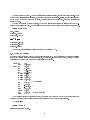
After loading the data and program les, the step instruction can be used to execute the rst 10 instructions. At this point, the last MULTD instruction has just issued. The stats command can display the stalls
and pending operations.
(dlxsim) stats
stalls pending
Load Stalls = 0
Floating Point Stalls = 0
Pending Floating Point Operations:
multiplier
#0 : will complete in
multiplier
#1 : will complete in
multiplier
#2 : will complete in
multiplier
#3 : will complete in
1
2
3
4
more
more
more
more
cycle(s)
cycle(s)
cycle(s)
cycle(s)
87.964594
84.823002
81.681409
78.539816
==>
==>
==>
==>
F4:F5
F8:F9
F12:F13
F16:F17
It is intersting to see what happens after the next instruction is executed.
(dlxsim) step
stopped after single step, pc = loop+0x24: sd 0xfff8(r1),f8
(dlxsim) stats
stalls pending
Load Stalls = 0
Floating Point Stalls = 1
Pending Floating Point Operations:
multiplier
#2 : will complete in
multiplier
#3 : will complete in
1 more cycle(s)
2 more cycle(s)
81.681409 ==> F12:F13
78.539816 ==> F16:F17
Since the SD instruction was dependent on the rst MULTD instruction, a oating point stall occurred
so the MULTD could complete. This added stall cycle also caused the second MULTD to also complete.
The MULTDs have \caught up" with the SDs, and no more stalls will occur on this iteration. This is the
reason loop unrolling works. To run the program to completion, the go command can be used.
(dlxsim) go
TRAP #0 received
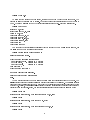
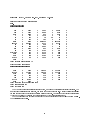
To dump all the statistics gathered, the stats command is used without any parameters.
(dlxsim) stats
Memory size: 65536 bytes.
Floating Point Hardware Configuration
1 add/subtract units, latency = 2 cycles
1 divide units,
latency = 19 cycles
4 multiply units,
latency = 5 cycles
Load Stalls = 0
Floating Point Stalls = 7
12
Branches:
total 7, taken 6 (85.71%), untaken 1 (14.29%)
Pending Floating Point Operations:
none.
INTEGER OPERATIONS
==================
ADD
0
ADDI
AND
0
ANDI
BFPT
0
BNEZ
J
0
JAL
LB
0
LBU
LH
0
LHI
MOVD
0
MOVF
MOVI2S
0
MOVS2I
OR
0
ORI
SD
28
SEQ
SGE
0
SGEI
SH
0
SLE
SLLI/NOP
0
SLT
SNEI
0
SRA
SRLI
0
SUB
SUBUI
0
SW
XORI
0
Total integer operations = 74
1
0
7
0
0
0
0
0
0
0
0
0
0
0
0
0
ADDU
BEQZ
DIV
JALR
LD
LHU
MOVFP2I
MULT
RFE
SEQI
SGT
SLEI
SLTI
SRAI
SUBI
TRAP
0
0
0
0
29
0
0
0
1
0
0
0
0
0
7
1
ADDUI
BFPF
DIVU
JR
LF
LW
MOVI2FP
MULTU
SB
SF
SGTI
SLL
SNE
SRL
SUBU
XOR
0
0
0
0
0
0
0
0
0
0
0
0
0
0
0
0
ADDD
0
ADDF
0
CVTF2D
0
CVTF2I
0
DIVD
0
DIVF
0
GED
0
GEF
0
LED
0
LEF
0
MULTD
28
MULTF
0
SUBD
0
SUBF
0
Total floating point operations = 28
Total operations = 102
Total cycles = 109
CVTD2F
CVTI2D
EQD
GTD
LTD
NED
0
0
0
0
0
0
CVTD2I
CVTI2F
EQF
GTF
LTF
NEF
0
0
0
0
0
0
FLOATING POINT OPERATIONS
=========================
The dynamic counts for all instructions are shown, as well as the statistics previously discussed. The
number of load stalls is seven in this case, compared to 28 in the rst example. This is the result of unrolling
the loop four times and providing four multiply units in hardware. An estimate of the clocks per instruction
(CPI) can be obtained by dividing the total cycles (109) by the total operations (102).
The two examples above give only a avor for the types of operations which may be done in DLXsim.
The possibilities are endless.
13
3 Internal Operation
Some information concerning how DLXsim operates internally may be useful to some users, particularly
those who wish to modify or enhance the simulator. This section provides an overview of the simulator and
a discussion of the underlying data structures used. This information is not necessary to use DLXsim. All
of the code discussed below is contained in the le sim.c.
3.1 Instruction Tables
DLXsim contains four tables which contain information about the DLX instruction set. The rst is opTable.
This table contains 64 entries corresponding to the 64 possible values of the opcode eld. Each entry consists
of an instruction-format pair. For example, the value of opTable[5] is fOP BNEZ, IFMTg indicating that
opcode 5 is a branch not equal to zero instruction, which uses the I-type format. Several entries in this table
have OP RES as the instruction. These entries are reserved for future extensions to the DLX instruction set.
The zero opcode indicates a dierent table should be used to identify the instruction. A second table
called specialTable handles this case. In this table are all the register-register operations. The format is
not specied explicitly for these instructions (as it was in opTable) because they are all R-type format.
These instructions all contain a zero in the opcode eld and a function encoding in the lower six bits of
the instruction word. There is also room in this table for expansion by using entries currently containing
OP RES.
An opcode of one indicates a oating point arithmetic operation. A third table, FParithTable handles these
instructions. As with specialTable, all instructions in this table have R-type format. The exact operation
is again specied by the lower six bits of the instruction word, which are used to index into this table.
Currently 32 entries contain OP RES and are available for future expansion to the oating point instruction
set.
The nal table is operationNames. This table contains a list of all the integer instruction names followed
by the oating point instruction names. Each group is arranged alphabetically. These tables are used to
print out the names of the instructions when a dynamic instruction count is requested.
3.2 Simulator Support Functions
This subsection describes the various routines which handle simulator commands and provide support for
the main simulator code. The function Sim Create initializes a DLX processor structure and is invoked
when DLXsim is rst started. The memory size of the machine along with the oating point hardware
specication (i.e. unit quantities and latencies) are specied as parameters.
Two functions, statsReset and Sim DumpStats, process the stats command in DLXsim. The former
resets all the statistics to zero, and the latter processes requests for various statistics. The statistics currently
taken during simulation are: load stalls, oating point stalls, dynamic instruction counts, and conditional
branch behavior. In addition, the oating point hardware and pending oating point operations can also be
examined. See the description of the stats command for more information on how to request and reset the
various statistics.
The functions Sim GoCmd and Sim StepCmd process the simulator's go and step commands, respectively.
See the description of these commands for more information on using them.
The functions ReadMem and WriteMem provide the interface between the simulator and the DLX memory
structure. They insure that the address accessed is valid, which means in must be within the memory's range
and it must be on a word boundary. Otherwise, appropriate error handling occurs.
3.3 Compilation of Instructions
To improve eciency, DLXsim \compiles" the instructions as it rst encounters them. To understand how
this works, it is necessary to examine the structure of a single word of the DLX memory. A single memory
word contains several elds: value, opCode, rs1, rs2, rd, and extra. A DLX program to be simulated is written
in DLX assembly language. Such a program is automatically assembled into machine code as it is loaded.
14
The actual machine codes are stored in the value elds of the memory words. The value eld represents the
number actually stored at a particular memory word. The opCode eld of each memory word is initially set
to the special value OP NOT COMPILED.
When the simulator executes an instruction, it rst examines the opCode eld of the memory word
pointed to by the program counter. If this eld is a valid opcode (specied in the tables discussed above), the
appropriate action for that instruction occurs. If the opCode eld contains the value OP NOT COMPILED,
the function Compile is invoked. This function looks at the actual word stored in the value eld. The
bits corresponding to the opcode and function elds are examined to determine what the instruction is.
Depending on the instruction type, the two source register speciers and destination register specier may
be extracted and stored in the elds rs1, rs2, and rd. If a 16-bit immediate value is present (for I-type
instructions) or a 26-bit oset is present (for J-type instructions), this value is extracted and stored in the
extra eld of the memory word. The special code for the instruction is stored in the opCode eld of the
word, which previously contained the value OP NOT COMPILED. These special codes are not the real DLX
opcodes, but rather the pseudo-opcodes dened in the le dlx.h.
When a compiled instruction is subsequently encountered, no shifting or masking operations are required
to access the register speciers or immediate values; the required information is already present in the
appropriate elds of the memory words (rs1, rs2, rd, and extra). This allows the simulator to execute much
faster. The actual machine code for the instruction can still be examined through the value eld, and this is
the value printed when the word is examined with the get command.
3.4 Main Simulation Loop
Simulate is the main function of the simulator. The heart of this function is basically a very large switch
statement, based on the opCode eld of the memory word pointed to by the program counter. There is a
case for each integer and oating point instruction. Simulate loops through the basic fetch-decode-execute
cycle until a stop command is received or some other exceptional condition occurs.
3.4.1 Load Stalls
DLX has a latency of one cycle on load instructions. In other words, the result is not yet present in the
destination register on the cycle immediately following the load instruction. To address this problem, DLX
has load interlocks which cause the pipeline to stall if an instruction immediately following a load instruction
reads the value in the load's destination register. DLXsim records the occurance of these load stall cycles
for statistical purposes. Several variables are set during the processing of the following load instructions: LB,
LBU, LH, LHU LW, LF, and LD. LHI is not included since the value to be loaded is contained in the instruction
and there is no extra latency. For the other load instructions, the destination register (or registers in the
case of load double) are stored in loadReg1 and loadReg2 (if this is a load double). The corresponding values
to be stored in these registers (on the next cycle) are stored in loadValue1 and loadValue2.
When an instruction that reads registers (such as an ADD instruction) is encountered during simulation,
the contents of loadReg1 and loadReg2 are examined before any other action occurs. If either of the registers
specied by these variables were loaded in the previous instruction, a load stall is detected and tallied.
Dierent register elds must be checked for dierent instructions. All the load stall detection logic is
contained in the macros at the top of the Simulate function denition.
Of interest is the fact that while load stalls would slow down the execution speed of a real DLX machine,
they do not aect the performance of the simulator. This is because load stall cycles are not actually
simulated. Instead, it is simply noted that a load stall occurred at a particular point, and execution proceeds
normally.
3.4.2 Dynamic Instruction Counts
Statistics on the number of each type of instruction executed are also recorded during simulation. This is a
simple operation of incrementing the appropriate element of the array operationCount, which is indexed by
the pseudo-opcodes discussed above. The information in the array can be accessed by the stats command.
15
3.4.3 Conditional Branch Behavior
DLXsim also keeps statistics on the conditional branch behavior during program execution. There are four
instructions in this category: BEQZ, BNEZ, BFPT, and BFPF. The latter two instructions are branches based
on the status of the oating point condition register. Two elds of the DLX machine structure, branchYes
and branchNo record how many conditional branches where taken and not taken, respectively. These values
are accessible via the stats command.
3.5 Floating Point Execution Control
A large portion of the DLXsim code is devoted to the oating point side of the machine. The oating point
scheme currently implemented requires instructions to issue in order, but they may complete out of order.
In addition to managing the allocation of the oating point units, DLXsim must also handle all the hazard
checking associated with out of order completion of instructions. By requiring instructions to issue in order,
the write-after-read (WAR) hazard is avoided. The three hazards which may occur are read-after-write
(RAW) hazards, write-after-write (WAW) hazards, and structural hazards.
3.5.1 Floating Point Data Structures
The variables and data structures which manage the oating point execution are all declared in the le
dlx.h as part of the basic DLX structure. The variables num add units, num div units, and num mul units
specify how many of each type of oating point execution unit are available on the machine. The variables
fp add latency, fp div latency, and fp mul latency specify the corresponding latencies (in clock cycles) of each
of the execution units. All six of these variables have default values which may be overridden via command
line parameters when DLXsim is invoked.
The variable FPstatusReg is the status register which is examined on a BFPT or BFPF instruction. The
various oating point set instructions (EQF, NED, etc.) write to this register.
The array fp add units contains the status of all the oating point adders during execution. If fp add units[i]
is zero, adder i is available. A non-zero value means that the unit is currently performing an operation {
the value species the clock cycle when the operation will complete. The array fp div units and fp mul units
contain analogous information for the oating point dividers and multipliers. All three structures can be
accessed through the array fp units which is an array of pointers to the three execution unit status arrays.
The array waiting FPRs contains 32 elements, corresponding to the 32 oating point registers in DLX. A
zero in waiting FPRs[i] means oating point register Fi can be read from; it contains its most current value.
A non-zero value means register Fi is the destination register of a pending oating point operation (one
which has issued but not yet completed). Attempting to read or write to such a register means a hazard
condition exists. The non-zero value indicates the cycle at which the writeback to the register will occur.
The variable FPopsList points to the chain of pending oating point operations. Each item in this chain
is of type FPop, a structure with the following elds:
type
Indicates the type of operation. Normally this is implied by what type of oating point unit is
executing the operation, however adders can perform both additions and subtractions.
unit
The unit number of the execution unit which is executing the operation.
dest
The destination register for the operation. For a double precision operation, this is the lowernumbered destination register.
isDouble Indicates if the operation is single or double precision.
result
An array of two oats used to store the result of the operation (only the rst element is used for
single precision operations). The result is actually computed at the time of issue.
ready
The cycle when the operation will complete and writeback will occur.
16
nextPtr Points to the next FPop in the chain of pending operations.
To maximize performance, the list of pending oating point operations is sorted based on when the operations
will complete. The operation which will complete soonest is at the head of the list.
The variable checkFP is a copy of the ready eld of the rst oating point operation on the pending
operation list. If its value is zero, no oating point operations are pending. Otherwise checkFP indicates
when the next (soonest) oating point operation will complete. This provides for very quick checking in the
fast-path of the simulator. Only one value needs to be checked in a cycle when no writebacks should occur.
Many of the previously discussed structures refer to a clock cycle count when a particular operation will
complete. The current clock cycle is kept in the variable cycleCount. This variable is incremented each time
the simulator executes its main loop. It is also incremented an extra time when a load stall is detected
since the oating point units are still executing during a load stall. When the cycle count reaches a large
value specied by the constant CYC CNT RESET, cycleCount is \reset" back to a small number (5), and all
references to clock cycles in the oating point data structures are adjusted accordingly. This operation is
necessary to prevent cycleCount from overowing, becoming negative, and thereby wreaking havoc on the
sorted list of pending operations. Making cycleCount an unsigned integer does not work, since there are still
problems with sorting the pending operations when cycle counts \wrap around" to zero.
3.5.2 Issuing Floating Point Operations
The function FPissue initiates a oating point operation. It is called from eight of the switch cases in the
main loop: ADDF, DIVF, MULF, SUBF, ADDD, DIVD, MULD, and SUBD. When a oating point instruction
issues, three hazard conditions must be checked. A structural hazard occurs if a oating point unit of the
required type is not available. A RAW hazard occurs if one of the source operands is the destination of a
pending oating point operation. Finally, a WAW hazard occurs if the destination register is the destination
register of a pending oating point operation. All three conditions can be checked by examing the oating
point data structures discussed above. If any of these hazards are present (and there may be more than one),
the current instruction is not issued. Instead a non-zero value is returned which indicates the soonest cycle
when one of the hazard conditions will be over. This may be a cycle when one of the oating point units
will complete its current operation (eliminating a structural hazard), or when some register will be written
back (eliminating a RAW or WAW hazard). When the caller receives a non-zero value from FPissue, the
appropriate number of oating point stalls are simulated by adjusting the variables cycleCount and FPstalls.
The function FPwriteBack (see below) is called to perform any writebacks which may now occur. Then
FPissue is re-invoked. If another hazard condition exists, the whole process may be repeated, but eventually
all of the hazard conditions will terminate.
If no hazards are present, the instruction is issued. That is, an new FPop structure is placed in the
appropriate spot in the pending operations list. The appropriate elements of waiting FPRs are also set to
indicate that the destination registers are waiting for values to be written back. FPissue returns a zero value
to indicate a successful issue, and the simulation continues.
3.5.3 Writing Back Floating Point Results
The function FPwriteBack is the second function involved in oating point execution. It is called whenever
cycleCount reaches checkFP, indicating that a result is ready to be written back on the current cycle. FPwriteBack does exactly that. It removes the rst FPop from the list of pending operations, and stores the
result (computed at time of issue) in the appropriate register(s). It also zeroes the appropriate element(s)
in waiting FPRs. Since more than one operation may complete on the same cycle, FPwriteBack repeats this
process until the value in the ready eld of the operation at the head of the list exceeds the current value in
cycleCount.
3.5.4 Handling RAW and WAW Hazards
The function FPissue (discussed above) handles the RAW and WAW hazards when a new oating point
operation is issued. However, several other instructions can generate such hazards. Any instruction which
17
reads from or writes to a oating point register must check that the register is not the destination of a
pending operation. The following instructions fall into this class:
Loads LF and LD.
Stores
SF and SD.
Moves
MOVFP2I, MOVI2FP, MOVF, MOVD.
Converts CVTD2FP, CVTD2I, CVTFP2D, CVTFP2I, CVTI2D, CVTI2FP.
Sets
SEQF, SNEF, SLTF, SLEF, SGTF, SGEF, SEQD, SNED, SLTD, SLED, SGTD, SGED.
When any of these instruction are executed, a call to FPwait is made. This is the third and nal function for
handling oating point execution. It checks that all writebacks into the appropriate registers have occurred.
The number of registers which need to be checked varies. For a LF instruction, only a single register needs to
be checked, while four registers must be checked on a MOVD. If any of the registers are the destinations of
pending operations, FPwait will adjust cycleCount and FPstalls appropriately, and call FPwriteBack to write
the results back to the registers. When FPwait returns, all RAW and WAW hazard conditions will have
passed.
18