1
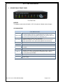
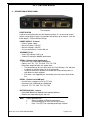
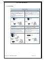
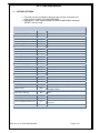
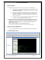
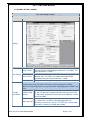
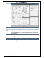
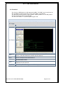
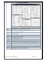
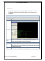
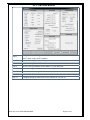
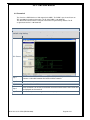
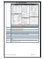
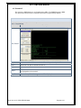
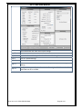
SS-77 uTMS
User Manual
SS-77 uTMS USER MANUAL
REVISION HISTORY
Revision 01
Revision 02
Revision 03
Revision 04
Revision 05
Revision 06
Revision 07
Revision 08
DOC. NO: SS-77 uTMS (REVISION 08)
Original document
PHO command
IPS PABX
ECC and PRT
PABX Management
Using NG Tool
Programming Scenarios
FTP CLIENT
MMI password
Through Connection
2009/05/19
2009/10/01
2010/01/21
2010/06/24
2011/05/13
2011/07/06
2011/07/22
2011/08/12
Page 2 of 37
SS-77 uTMS USER MANUAL
CONTENTS
1.
PURPOSE ........................................................................................... 4
2.
FEATURES.......................................................................................... 4
3.
DESCRIPTION OF FRONT PANEL ......................................................... 5
4.
DESCRIPTION OF REAR PANEL ........................................................... 6
5.
APPLICATIONS ................................................................................... 7
6.
FACTORY SETTINGS ........................................................................... 8
7.
GETTING STARTED ............................................................................. 9
8.
USING THE NG PROGRAMMING TOOL .............................................. 9
9.
PROGRAMMING SCENARIOS AND EXAMPLES.................................. 16
10.
10.1.
10.2.
10.3.
10.4.
10.5.
COMMANDS.................................................................................... 26
PABX MANAGEMENT MODE ........................................................... 32
TCP CALL-BACK-MODE .................................................................... 32
FTP TMS CLIENT .............................................................................. 33
THROUGH CONNECTION – LAN TO SERIAL PORT 1 .......................... 34
REMOTE ACCESS TO SERIAL CONNECTED EQUIPMENT .................... 35
11.
DONGLE OPERATION ....................................................................... 35
12.
12.1.
12.2.
12.3.
QUICK SETUP GUIDES ...................................................................... 36
ASCII DATA COLLECTION VIA SERIAL PORT ...................................... 36
DATA COLLECTION ON ALCATEL 4400 / OMNI PCX .......................... 36
DATA RETRIEVAL USING UDP LOGGER ............................................. 36
13.
CONTACT DETAILS ........................................................................... 37
DOC. NO: SS-77 uTMS (REVISION 08)
Page 3 of 37
SS-77 uTMS USER MANUAL
1.
PURPOSE
The purpose of the SS-77 is that of a multifunction data buffer. It is designed to
collect data from a variety of sources (primarily PABXs) using various protocols.
The data can then be retrieved from the SS-77 using a number of different
methods. This allows the buffer to be used where the link between the data
processing solution and the data source may be intermittent or otherwise prone to
data loss.
The SS-77 can also be used to provide remote access to serially connected
equipment (RS-232) by Ethernet.
The data can optionally be time stamped by the buffer.
2.
FEATURES
FEATURES
• Memory capacity of 8 megabytes
• Battery backup
• LEDs to indicate buffer status
• 10MBit or 100MBit Ethernet operation
• Dongle Function
• Built-In tests for
Supply voltages
LEDs
• Hardware Reset Button
Allows loading of default settings
• Audio Beeper
Alerts users to status changes
Warnings of system failures
• Data collection options
Via Serial ports
o Port 1 - Baud rates from 1200
baud to 115200 baud
o Port 2 - Baud rates from 1200
baud to 19200 baud
Via Ethernet
o Active TCP/IP
o Passive TCP/IP
o UDP (e.g. Syslog)
• Data retrieval
Via Serial Port
o Auto Dump using handshake line
o ASCII protocol (‘S<enter>’ to
retrieve a record)
Via Ethernet
o NetLog standard protocol
o UdpLog standard protocol
o Auto Dump on Ethernet
connection.
• Protocol translation
• Supports the following Internet Protocols
DHCP
SNTP
NBNS
DNS
TCP
UDP
Binary
ASCII
STX-ETX
RoboDog
DOC. NO: SS-77 uTMS (REVISION 08)
Page 4 of 37
SS-77 uTMS USER MANUAL
3.
DESCRIPTION OF FRONT PANEL
The Front Panel
BEEPER
The beeper sounds when the buffer is 95% full and also indicates status changes.
LED INDICATORS
LED INDICATORS
DOWN LOAD
• Indicates that the logging server has responded to buffer.
• ON when logging server has responded to buffer or a TCP session is
connected to Socket 0 (either MMI or NetLog), flicks off when data sent.
• Off when Serial connected, flashes on when data sent.
HEARTBEAT
• Flashing indicates that the unit is operational.
• Double flash indicates some data in the buffer (64 or more characters)
• Triple flash indicates more data in buffer (2048 or more characters)
50% full
• This LED flashes when buffer is 50% full.
80% full
• This LED flashes when buffer is 80% full.
IP OK
• Indicates that the IP address is OK or that DHCP was successful if
enabled.
TIME SVR
• Indicates the time server returned a valid time.
PABX RX
• Indicates when data is received from PABX, either via the serial or via the
LAN interface, thereby providing visual confirmation that the buffer is
receiving data from the PABX.
PABX CON
PWR
• Indicates when IP connection is active to the PABX.
• This LED indicates that power is being received from the external 12 volt
power supply.
DOC. NO: SS-77 uTMS (REVISION 08)
Page 5 of 37
SS-77 uTMS USER MANUAL
4.
DESCRIPTION OF REAR PANEL
The rear panel
RESET SWITCH
Used for resetting the buffer and the Network Interface. It is also used to restore
default settings by pressing the reset button and holding it for 6 seconds. (Until the
buffer beeps) – Refer to Default Settings
POWER SUPPLY - External
o External power supply
o Minimum Voltage = 10 VDC
o Maximus Voltage = 20 VDC
o Current requirements = Under 100 mA
ETHERNET RJ-45
o Green LED indicates LINK is up
o Yellow LED indicates 100MBit speed active
SERIAL 2 (Default serial logging port)
o Baud rates from 1200 baud to 19200 baud
o Options: 8N1, 7E1, 7O1, 7N1, 8N2, 7E2, 7O2, 7N2
o Handshake output for buffer full / power down
The Handshake will be set inactive when the Flash Memory is full and there
is capacity for 100 characters left in the input buffer.
To prevent continuous up/down the Handshake will be activated when in
input buffer has been emptied.
If the data is not stopped by the handshaking line then excess data will be
lost.
SERIAL 1 (Default serial MMI port)
o Used to access equipment such as FCT Mux
o Baud rates from 1200 baud to 115200 baud
o Only 8N1, 7E1, 7O1, 8N2, 7E2, 7O2, 7N2
BATTERY BACKUP – Internal
o AAA NiMH 500mAH to 1000mAH rechargeable batteries.
o Batteries are replaceable by the end user
Note:
Battery backup allows:
Orderly shutdown of Ethernet connections
Continued logging on Serial Port for up to 2 days
Date / Time (RTC) for extended period up to 2 weeks
DOC. NO: SS-77 uTMS (REVISION 08)
Page 6 of 37
SS-77 uTMS USER MANUAL
5.
APPLICATIONS
BASIC SETUP
Serial to LAN
The following example shows how data can
be collected from the PABX system using a
serial interface. The TMS software then
collects data via the LAN interface using TCP
or UDP protocol.
Refer to section 9.Programming Scenarios
and Examples.
LAN to LAN
The following example shows how data can
be collected from the PABX system using a
LAN interface. The TMS software then also
collects the data via the LAN interface.
Refer to section 9.Programming Scenarios
and Examples.
DOC. NO: SS-77 uTMS (REVISION 08)
LAN to Serial
The following example shows how data can be
collected from the PABX system using the
LAN interface. The TMS software then collects
data via the serial interface.
Refer to section 9.Programming Scenarios and
Examples.
Remote access to serially connected
equipment. (Etc. FCT Mux)
The following example shows how a PC can
access a remote serial device via the LAN
interface of the SS-77.
Refer to section 11. Remote Access to Serial
Connected Equipment.
Page 7 of 37
SS-77 uTMS USER MANUAL
6.
FACTORY SETTINGS
1. The Buffer can be set to default settings by pressing the reset button and
holding it for 6 seconds. (Until the buffer beeps).
2. Alternatively, if serial communications has been established the command
‘DEFDAT’ can be issued.
DEFAULT VALUES
Setting
Command
Value
Serial 1 baud rate
SB1
115200 baud
Serial 2 baud rate
SB2
19200 baud
Serial 2 data/parity
S2P
8N
Default MMI port
MMP
Serial 1
Default Logging Port
SDL
Serial 2
PABX translation
XLT
ASCII
Short Record Elimination length
SRE
1
Beeper Volume
BPV
50%
Auto Dump
SAD
Disabled
Auto Dump Timeout
SAT
10 seconds
RoboDog Sync Char
RSY
‘R’
RoboDog Character count
RCT
3
TMS Server (UdpLog)
TMI
Blank, Not Set.
Time Server
STS
time-a.nist.gov
Time Zone
STZ
-120 minutes for South Africa
DHCP
UDH
Enabled
Use Ten MBit
UTM
Off
Local IP address
LIP
192.168.0.234
Subnet mask
SNM
255.255.255.0
Gateway
GWA
0.0.0.0
DNS IP address
DNS
0.0.0.0
NetBIOS Name
NBN
‘SS-77-ABCDEF’ where ‘ABCDEF’ are the last 6 digits
of the MAC address
Buffer Name (UdpLog)
BID
‘SSABCDEF’ with ABCDEF the last 6 digits of the MAC
address
Socket 0 Connection Type
PRT
TCP Passive
Socket 0 Local Port
LPT
23 – Telnet address for LAN access
Socket 2 (UdpLog Socket) Port
LPT
12345 – must be something other than 1122 which is the
remote port
Echo
DOC. NO: SS-77 uTMS (REVISION 08)
ECHO
Off
Page 8 of 37
SS-77 uTMS USER MANUAL
7.
GETTING STARTED
7.1. As delivered from the factory the buffer can be accessed for setup in the following ways:
7.1.1.
On serial port 1 using a communications package such as HyperTerminal or using
the NG Tool. The port settings are 115200 baud, 8 data bit, no parity, 1 stop with
hardware flow control disabled.
7.1.2.
Via LAN. Use an Ethernet Telnet terminal package. The SS-77 defaults to using
DHCP with its NetBIOS Name set to SS-77- followed by the last 6 digits of the
MAC address. For example, if the MAC address is 00:21:44:12:34:56 the NBNS
name is ‘SS-77-123456’.
7.1.3.
The buffer can also be accessed and programed using the NG Buffer Tool. Please
see section 8.1 “Using the NG Software Programming Tool.”
7.2. Character Echo. To function correctly with NetLog and other data collection packages the local
echo of typed characters is disabled. In order to view what is being typed it is necessary to
enable local echo. The simplest way to do this is to enter the command “ECHO ON”. This will
automatically be cancelled when the SS-77 is reset. Alternatively one can enable echo in
HyperTerminal by selecting:
“Properties->Settings->ASCII Setup->Echo typed characters locally”
This session can be saved for future use as SS-77 and the settings will be retained.
8.
USING THE NG PROGRAMMING TOOL
Note: The NG Programming Tool can be downloaded from SS Telecoms web site.
8.1. NG MAIN TERMINAL SCREEN
NG Tool Main Screen
The SS-77 Tool can be used as a terminal program enabling the user to issue commands via the
terminal screen. The main purpose of the Tool is to make programing of the buffer user-friendly.
Setting
Description
Main Screen
DOC. NO: SS-77 uTMS (REVISION 08)
Page 9 of 37
SS-77 uTMS USER MANUAL
Setup
This will open the Setup configuration screen explained below.
File
When upgrading the firmware of the SS-77. Use the file menu to
select the firmware file to be uploaded. These type of file are
normally has an HEX extension.
PABX Management Mode
This mode allows remote access to a PABX Ethernet port through
the buffer. It allows commands to be passed from either the Serial
MMI port or the Ethernet MMI port to the PABX Ethernet port.
Menu Items
The buffer will attempt to establish a connection to the PABX using
PBX Mode the ‘LOG LAN IP addr’ with the specified port number. When the
connection is established the buffer will respond with:
PMS: Connected <port>
A twenty second timer is started so that if no commands are sent to
the PABX the link will be disconnected with the message:
PMS: Disconnect
Front
To change the font size and type of the text displayed in the
terminal screen.
Colour
To change the terminal background colour and text colour.
Close
Closes the NG Tool application.
Remote
This setting should be enabled when the firmware updated is done through an
Firmware Upload TCP(LAN) connection.
Host Name &
Port
The IP or Hostname to make a connection to.
This would normally be the IP Address or Hostname of the buffer. The default
MMI(Programming Interface) and Buffer port is 23.
Use the Connect and Disconnect buttons for TCP.
Com Port
Com Port
Use the Dropdown box to select the com port.
This is com port to use on the local PC for connecting to the buffer.
Baud Rate Baud rate to use.
The default baud rate to connect to Serial 1 of the buffer is 115200.
DOC. NO: SS-77 uTMS (REVISION 08)
Page 10 of 37
SS-77 uTMS USER MANUAL
8.2. NG TOOL SETTINGS SCREEN
NG Tool Settings Screen
This screen is used to configure and upload the SS-77 settings
Setting
Description
Settings
Serial 1 Baud
Set the Serial Port 1 baud rate. This is the default MMI port. The
buffer can be accessed and programmed via this serial port. The
default baud rate is 115200
Serial 2 Baud
Set the Serial Port 2 baud rate. This is the default logging port for
collecting data. The PABX serial output would normally be
connected to this port. Default baud rate is 19200
Serial 2 Parity
Sets the number of data bits and parity format for Serial Port 2.
Port Settings
The SS-77 has the ability to route the LAN socket #1 through the MMI serial port 1.
Amongst other things this allows LAN access to the serial port on a PABX.
Note: This mode of operation is only possible when LAN logging of the PABX is not
used.
Through
Connection
Enable Trough
Connect
This will enable a through connection between the LAN socket
with the TCP port that is specified and the Serial Port 1of the SS77. Note: When enabling this feature the Serial MMI port 1 will be
set to Silent Mode.
Set the local port to listen for incoming connections. This can be
any number from 1 to 65524. Note that certain ports are
LAN Local Port
commonly used for tasks such as FTP, SMTP etc. so care needs
to be taken in choosing a suitable port number.
DOC. NO: SS-77 uTMS (REVISION 08)
Page 11 of 37
SS-77 uTMS USER MANUAL
This sets the serial port to be used for programming of the buffer
also known as the MMI Port. Because the buffer can also be
programmed via the LAN interface an incoming connection on
the TCP port will automatically become the MMI port. While the
Default MMI Port
TCP link is established the serial port control will be disabled.
The default MMI Port is Serial 1.
Note: When the Through Connection feature is enabled the
Serial MMI port 1 will be set to Silent Mode.
Logging
Settings
Date Insertion
This is used to enable the insertion of the Date and Time either
before the record or after the record.
AutoDump
Enable Auto Dump. Default is ‘OFF’. When enabled the buffer
will dump its stored data when the Serial 1 handshake is enabled
or when an MMI port (socket 0) Ethernet connection is made.
Compress Data
Compresses the data records.
Discard oldest
Data
When enabled, the buffer will discard old data and log the new
data once the buffer is full.
Enable Call
Centre
Enables the Call Centre mode.
When this option is enabled the buffer will output call records on
serial port 1 while logging the data simultaneously.
Note that when Serial Port 2 is used for logging it is necessary to
ensure that Serial Port 1 is set up to use a baud rate that is the
same or higher than Serial Port 2.
By default this feature is disabled.
AutoDump TO
Sets the delay from connection active until dumping starts. The
time out is in seconds. This allows short glitches to be ignored.
(Such as mouse probing when a PC starts up).
BEEP Volume
Beeper volume. Where 0 is off and 100 is the maximum volume.
PAD Reset
Timer
Set the PAD reset timer. This timer causes the LAN module to
be restarted when it expires. It can be disabled by setting it to
zero. Attempts to set it below 30 minute will result in it being set
to 30 minutes. The maximum value is 255 minutes.
The timer is restarted when the SS-77 receives an ‘S’ or ‘SEND’
command.
Use PC Time
Sets the current date and time of the SS-77 to the PC’s Date and
Time.
DOC. NO: SS-77 uTMS (REVISION 08)
Page 12 of 37
SS-77 uTMS USER MANUAL
Use DHCP
Enable this when using DHCP.
Local IP
Sets the local IP address of the Buffer. This setting is ignored
when DHCP mode is enabled.
LAN Settings Subnet
Sets the Subnet Mask to use. This setting is ignored when
DHCP mode is enabled.
Gateway
Sets the Gateway Address to be used. This setting is ignored
when DHCP mode is enabled.
DNS Server
Sets the DNS server address to be used. This setting is ignored
when DHCP mode is enabled.
NetBios Name
This will set the NetBIOS Name. The default name is ‘SS-77ABCDEF where the ABCDEF is the last 6 characters of the MAC
address. The name can be set to any alpha-numeric string up to
15 characters long.
MMI Listen Port
Sets the port number for the SS-77 that it will listen on for MMI or
NetLog connections via the LAN interface.
Use Link Signal
When enabled the buffer checks the physical link in relation to
stopping or starting the LAN functions. When switched ‘OFF’ the
Link Status is ignored and the LAN interface is started up just
using some timing delays.
LAN Speed
Selection between 10Mbit and 100Mbit. On some LANs autonegotiation of LAN speed may cause LAN link issues, so 10Mbit
can be manually selected.
DOC. NO: SS-77 uTMS (REVISION 08)
Page 13 of 37
SS-77 uTMS USER MANUAL
UDP Logger
This option is used when configuring the
buffer to dump data to Udp Logger.
FTP Client
This option is used when configuring
the buffer to push data to a FTP server.
TMS Protocol
Buffer ID
This sets the buffer ID as used by UdpLog. It is an 8 character name.
If a name is shorter than 8 characters is used then it will be padded to
8 characters with ‘_’ (Underscore) characters. If non alpha numeric
characters are used they will also be replaced with ‘_’.
Sets the address of the UdpLog server. Either FQDN format
(udplog.co.za) or dotted IP (123.1.1.234) is suitable. Dotted format
TMS Server will be necessary if no DNS server is available. Note, the addresses
shown are not valid addresses, merely examples of the format to be
used.
UDP Settings TMS Server Sets the port number to use for communicating to Udp Logger. The
default port is 1122. Other values may be used if the UdpLog server
Port
installation requires it.
Sets the address of the timer server. Either FQDN format (timeTime Server a.nist.gov) or dotted IP (129.6.15.28) is suitable. Dotted format will be
necessary if no DNS server is available.
Time Zone
Set the time offset from UTC in minutes. Negative for East, positive
for West. South Africa (the default) is -120.
UDP Packet Sets the packet size of the UDP packet to be used when logging
Size
using UdpLog.
DOC. NO: SS-77 uTMS (REVISION 08)
Page 14 of 37
SS-77 uTMS USER MANUAL
FTP
Settings
Buffer ID
The records in the buffer will be downloaded to a file. The
file name will be the buffer ID and the current DateTime.
E.G.:BUFFERID_YYMMDD_hhmmss.log
FTP Server
Sets the address of the FTP server. It needs to be in dotted
notation (E.g 196.213.211.32)
FTP Username
Sets the FTP Username. Maximum length is 12 characters.
FTP Password
Sets the FTP password for Username. Maximum length is
12 characters.
FTP Path
This selects the directory from which to extract the files or in
the case of FTP push the directory for uploading the
records.
FTP Connection Time
Every Hour
This will set the FTP client to upload the
data file every hour at the Minute
specified.
Specific Time
Sets the hour and minute upon which
the FTP Client will upload the data file.
This is to provide a staggered download
from the field to reduce the peak load on
the server.
The Translation Option to use. This depends on the make and model
of the PABX. Most PABX system use standard ASCII. ASCII is the
default.
Translate
Option
Binary
Unformatted data – any character sequence
ASCII
Vanilla ASCII using CR / LF
RoboDog
Proprietary Security
Stx Etx
ASCII special start and end characters
Default Log
Port
Sets the logging port to be used in the event that a ‘generic’
translation option is used.
LAN Log
Mode
This sets the mode of the LAN logging socket.
Protocol
Settings
Server
The buffer will be passive and will wait for an incoming
connection from the PABX
Client
The buffer will be active and will make an connection to
the PABX
Short Record Valid values are from 0 to 39. If this value is set to a value other than
Elimination
0, it will prevent the storage of a record that has less characters than
it is set. I.E. Setting it to 10 will prevent the storage of records with
less than 10 characters. It is only active for ASCII and STX ETX
modes. The default value is 1 ensuring that empty lines (CR/LF only)
are eliminated.
LAN Log IP
Address
If the LAN Log mode is set to Client, this would be the PABX IP
address to which the SS-77 will connect to, to retrieve data.
LAN Log
Local Port
This sets the LOCAL port number. If the LAN Log mode is set to
Server, this would be the port that the buffer would listen on for
incoming connections from the PABX.
LAN Log
This sets the REMOTE port number. It is the port number on which
Remote Port the buffer will connect to the PABX. It is not used if the mode is TCP
Passive (Server).
DOC. NO: SS-77 uTMS (REVISION 08)
Page 15 of 37
SS-77 uTMS USER MANUAL
9.
PROGRAMMING SCENARIOS AND EXAMPLES
9.1. Scenario 1
The client has a PABX that has a serial output for the CDR’s. The PABX baud rate is 9600.
The data will be collected using the NetLog software. Netlog software uses an active TCP LAN
connection on port 23 to collect the data (CDR’s) from the buffer. The IP assigned to the buffer is
192.168.0.234.No date insertion is required.
Scenario 1
This explains how to setup the buffer to log data on the serial port and dump the data via LAN.
Description
Main Screen
Step 1
Connect a serial cable between the buffer serial port 1 and your PC.
Connect a serial cable between the buffer serial port 2 and the PABX.
Connect a LAN cable between the buffer and the network.
Step 2
Select the Com port to be used on the PC.
Step 3
Select Baud Rate 115200
Step 4
Once conneted. The version of the buffer firmware and the buffer status menu will
be displayed on the terminal.
Step 5
Click on Setup. The following screen will be displayed.
DOC. NO: SS-77 uTMS (REVISION 08)
Page 16 of 37
SS-77 uTMS USER MANUAL
Step 6
Change Serial 2 Baud to 9600
Step 7
Untick the “Before Record” field. This disables date insertion.
Step 8
Configure the LAN Settings that the buffer should use. Remember to disable “Use
DHCP” when using a statis IP address.
Step 9
Ensure that the MMI port is set to 23. This would be the port that the Netlog client
would connect to.
Step 10
Ensure that the Default Log Port is set Serial 2. This is where the PABX will be
connecting to
Step 11
Click on “Upload Settings”
Step 12
Click on “Save & Reset”
Step 13
Configure NetLog to collect data from the buffer on TCP port 23
DOC. NO: SS-77 uTMS (REVISION 08)
Page 17 of 37
SS-77 uTMS USER MANUAL
9.2. Scenario 2
The client has a PABX that has a LAN output for the CDR’s. The PABX is passive and listens on
TCP port 5003 for incoming connections. The IP of the PABX is 192.168.0.221
The data will be collected using the UdpLog software. UdpLog software uses the UDP protocol.
The IP assigned to the buffer is 192.168.0.234.
The UDP server address is sstelecoms.dyndns.org port 1122
Scenario 2
This explains how to setup the buffer to log data on the LAN port and dump the data via LAN to
UDP Logger.
Description
Main Screen
Step 1
Connect a serial cable between the buffer serial port 1 and your PC.
Connect a LAN cable between the buffer and the network.
Step 2
Select the Com port to be used on the PC.
Step 3
Select Baud Rate 115200
Step 4
Once conneted. The version of the buffer firmware and the buffer status menu will
be displayed on the terminal.
Step 5
Click on Setup. The following screen will be displayed.
DOC. NO: SS-77 uTMS (REVISION 08)
Page 18 of 37
SS-77 uTMS USER MANUAL
Step 6
Enable Century and ensure “Before Record “ is enabled.
Step 7
Configure the LAN Settings that the buffer should use. Remember to disable “Use
DHCP” when using a statis IP address.
Step 8
Under the TMS Settings configure the Buffer Name that will used to identify the
buffer on Udp Logger.
Step 9
Configure the Udp Logger IP or FQDN address in the TMS Server field.
Step 10
Set the Default Log Port to LAN Log.
Step 12
Set the LAN Log Mode to Client.
Step 13
Set the LAN Log IP Address to the PABX IP: E.g 192.168.0.221
Step 14
Set the LAN Log Remote IP to the PABX port: E.g 5003
Step 15
Under the TMS Settings. Set the TMS Server Address. E.g sstelecoms.dyndns.org
Step 16
Set the TMS server port. Default is 1122
Step 17
Click on “Upload Settings”
Step 18
Click on “Save & Reset”
Step 19
On UDP Logger add the Buffer ID to the contacts.
DOC. NO: SS-77 uTMS (REVISION 08)
Page 19 of 37
SS-77 uTMS USER MANUAL
9.3. Scenario 3
The client has a PABX that has a LAN output for the CDR’s. The PABX is passive and listens on
TCP port 5003 for incoming connections. The IP of the PABX is 192.168.0.221
The data will be collected via LAN using the NetLog software. The IP assigned to the buffer is
192.168.0.234.
Scenario 3
This explains how to setup the buffer to log data on the LAN port and dump the data via the LAN
interface using NetLog.
Description
Main Screen
Step 1
Connect a serial cable between the buffer serial port 1 and your PC.
Connect a LAN cable between the buffer and the network.
Step 2
Select the Com port to be used on the PC.
Step 3
Select Baud Rate 115200
Step 4
Once conneted. The version of the buffer firmware and the buffer status menu will
be displayed on the terminal.
Step 5
Click on Setup. The following screen will be displayed.
DOC. NO: SS-77 uTMS (REVISION 08)
Page 20 of 37
SS-77 uTMS USER MANUAL
Step 6
Configure the LAN Settings that the buffer should use. Remember to disable “Use
DHCP” when using a statis IP address.
Step 7
Set the Default Log Port to LAN Log.
Step 8
Set the LAN Log Mode to Client.
Step 9
Set the LAN Log IP Address to the PABX IP: E.g 192.168.0.221
Step 10
Set the LAN Log Remote IP to the PABX port: E.g 5003
Step 11
Click on “Upload Settings”
Step 12
Click on “Save & Reset”
Step 13
Configure NetLog to collect data from the buffer on TCP port 23
DOC. NO: SS-77 uTMS (REVISION 08)
Page 21 of 37
SS-77 uTMS USER MANUAL
9.4. Scenario 4
The client has a PABX that has a LAN output for the CDR’s. The PABX is passive and listens on
TCP port 5003 for incoming connections. The IP of the PABX is 192.168.0.221
The data will be collected via the serial port of the buffer using the NetLog software. The IP
assigned to the buffer is 192.168.0.234.
Scenario 4
This explains how to setup the buffer to log data on the LAN port and dump the data via the Serial
interface using NetLog.
Description
Main Screen
Step 1
Connect a serial cable between the buffer serial port 1 and your PC.
Connect a LAN cable between the buffer and the network.
Step 2
Select the Com port to be used on the PC.
Step 3
Select Baud Rate 115200
Step 4
Once conneted. The version of the buffer firmware and the buffer status menu will
be displayed on the terminal.
Step 5
Click on Setup. The following screen will be displayed.
DOC. NO: SS-77 uTMS (REVISION 08)
Page 22 of 37
SS-77 uTMS USER MANUAL
Step 6
Configure the LAN Settings that the buffer should use. Remember to disable “Use
DHCP” when using a statis IP address.
Step 7
Set the Default Log Port to LAN Log.
Step 8
Set the LAN Log Mode to Client.
Step 9
Set the LAN Log IP Address to the PABX IP: E.g 192.168.0.221
Step 10
Set the LAN Log Remote IP to the PABX port: E.g 5003
Step 11
Click on “Upload Settings”
Step 12
Click on “Save & Reset”
Step 13
Connect a serial cable between the buffer serial port 1 and your PC running
NetLog.
Step 14
Configure NetLog to collect data from the buffer using the COM Port on the PC
with baud rate set to 115200.
DOC. NO: SS-77 uTMS (REVISION 08)
Page 23 of 37
SS-77 uTMS USER MANUAL
9.5. Scenario 5
The client has a PABX that has a serial output for the CDR’s. The PABX baud rate is 9600.
The data will be collected via the serial port of the buffer using the NetLog software.
Scenario 5
This explains how to setup the buffer to log data on the Serial Port 2 and dump the data via Serial
Port 1 using NetLog.
Description
Main Screen
Step 1
Connect a serial cable between the buffer serial port 1 and your PC.
Step 2
Select the Com port to be used on the PC.
Step 3
Select Baud Rate 115200
Step 4
Once conneted. The version of the buffer firmware and the buffer status menu will
be displayed on the terminal.
Step 5
Click on Setup. The following screen will be displayed.
DOC. NO: SS-77 uTMS (REVISION 08)
Page 24 of 37
SS-77 uTMS USER MANUAL
Step 6
Select 9600 baud rate under Serial 2 port settings.
Step 7
Select Serial 1 as the Default MMI Port.
Step 8
Under the Protocol Settings select Serial 2 as the default Log Port.
Step 9
Click on “Upload Settings”
Step 10
Click on “Save & Reset”
Step 11
Connect a serial cable between the buffer serial port 1 and your PC running
NetLog.
Step 12
Configure NetLog to collect data from the buffer using the COM Port on the PC
with baud rate set to 115200.
DOC. NO: SS-77 uTMS (REVISION 08)
Page 25 of 37
SS-77 uTMS USER MANUAL
10. COMMANDS
COMMAND TABLE
Command
Description
ECHO
This will turn on the local echo of characters. It does not affect the download
when using UdpLog, but should be turned off for operation with NetLog or
other collection packages. The echoed characters can corrupt transmitted
records. Default is ‘OFF’. Input can be Y/N, T/F, E/D, 1/0 or ON/OFF.
SHOW
Displays most of the current settings of the SS-77. This display is sensitive
to the translation mode selected, so it will not display the Robodog setup if
ASCII mode is selected.
SAVE
This will save the current settings to non-volatile memory.
LOAD
This restores the settings from the non-volatile memory. This would
normally only be used when one wishes to discard changes made so far.
RESET
Resets the SS-77. This will cause the SS-77 to start running as if the reset
button was pressed. Any setup changes will be lost if they have not been
saved.
DEFDAT
Initializes the setup data (Factory Settings) except for the MAC address and
the Dongle Secret Code.
TIM
Sets the current date and time of the SS-77. If the setup data is not entered,
<YYMMDDhhmmss> then the time is displayed.
SB1 <baud rate>
Set the Serial Port 1 baud rate.
Valid rates are: 1200, 2400, 4800, 9600, 19200, 38400, 57600, 115200.
SB2 <baud rate>
Set the Serial Port 2 baud rate. Valid rates are: 1200, 2400, 4800, 9600,
19200.
S2P <port setting>
Sets the number of data bits and parity format for Serial Port 2.
The options are 8N, 7N, 7O or 7N. One or two stop bits are always
acceptable.
BPV <Volume>
Beeper volume. Volume < 0> = off, <100> = maximum
DOC. NO: SS-77 uTMS (REVISION 08)
Page 26 of 37
SS-77 uTMS USER MANUAL
COMMAND TABLE
Command
SRE <nnn>
Description
Short Record Elimination length is <nnn>. Valid values are from 0 to 39. If this
value is set to a value other then 0, it will prevent the storage of a record that
has less characters than it is set. I.E. Setting it to 10 will prevent the storage of
records with less than 10 characters. It is only active for ASCII and STX ETX
modes. The default value is 1 ensuring that empty lines (CR/LF only) are
eliminated.
Sets the logging port to be used in the event that a ‘generic’ translation option
is used. The available ports are:
Value Port Name
SDL <Value>
SDM <Value>
0
Serial Port 1
2
Serial Port 2
4
Ethernet Socket 1
Sets the serial port to be used in for MMI setup of the buffer. If socket 0 is set
up as a TCP listener then an incoming connection on that port will
automatically become the MMI port. While the TCP link is established the
serial port control will be disabled.
Value Port Name
0
Serial Port 1
2
Serial Port 2
Use the first few letters of the mode name. (XLT ALC will select the Alcatel
4400). Enough letters need to be entered so differentiate between options
otherwise the 1st match will be selected.
Value
XLT <Value>
Note:
Logging
Mode
Description
BIN
Binary
Unformatted data – any character sequence
ASC
ASCII
Vanilla ASCII using CR / LF
ROB
RoboDog
Proprietary Security
STX
StxEtx
ASCII special start and end characters
If an invalid or unauthorised option for XLT is selected an option list is displayed with the
authorised options marked:
DOC. NO: SS-77 uTMS (REVISION 08)
Page 27 of 37
SS-77 uTMS USER MANUAL
COMMAND TABLE
Command
Description
LIP <a.b.c.d>
Sets the local IP address to a.b.c.d This setting is ignored when DHCP
mode is enabled.
SNM <e.f.g.h>
Sets the Subnet Mask to e.f.g.h This setting is ignored of DHCP mode is
enabled.
GWA <i.j.k.l>
Sets the Gateway Address to i.j.k.l This setting is ignored of DHCP mode
is enabled.
DNS <m.n.o.p>
Sets the DNS server address to m.n.o.p This setting is ignored of DHCP
mode is enabled.
NBN <NetBIOS
Name>
This will set the NetBIOS Name. The default name is ‘SS-77-ABCDEF
where the ABCDEF is the last 6 characters of the MAC address. The
name can be set to any alpha-numeric string up to 15 characters long.
UDH <ON/OFF>
Use DHCP or not. Default is ‘ON’. Input can be Y/N, T/F, E/D, 1/0 or
ON/OFF
UTM <ON/OFF>
Set 10Mbit operation. Input can be Y/N, T/F, E/D, 1/0 or ON/OFF. When
this setting is enabled the buffer will only connect at 10Mbit and not
100Mbit. On some LANs auto-negotiation of LAN speed may cause LAN
link issues, so 10Mbit can be manually selected.
STS <time.server>
Sets the address of the timer server. Either FQDN format (time-a.nist.gov)
or dotted IP (129.6.15.28) is suitable. Dotted format will be necessary if no
DNS server is available.
STZ <time offset>
Set the time offset from UTC in minutes. Negative for East, positive for
West. South Africa (the default) is -120.
The SDI command is used to enable the insertion of the Date and Time
either before the record or after the record. The command parameters are
either low case to remove an option or upper case to enable an option.
Certain parameters automatically either remove others (you can’t have the
century without the year, so disabling the year disables the century) or
enables them (enabling the century automatically enables the year). The
parameter letters are:
Enable Disable Description
SDI <date
parameters>
A
a
Insertion AFTER the record data – fixed format
hhmmDDMMCCYY.
B
b
Insertion ‘Before’ the record data, allows some format
options.
C
c
Stores the Century giving a 4 digit year, only for ‘Before’
Y
y
Stores the year as 2 digits, only for ‘Before’
S
s
Stores the seconds, only for ‘Before’
Example:
To set the storage ‘Before, 2 digit year, no seconds’ input: “SDI BacYs”
The various flags can be set or enable individually, so to turn on seconds
use “SDI S”. This will set the seconds on. The result of the command is
displayed.
DOC. NO: SS-77 uTMS (REVISION 08)
Page 28 of 37
SS-77 uTMS USER MANUAL
COMMAND TABLE
Command
Description
VER
Displays the product identity and s/w version number. Typically:
‘SS-77 rev a.bc’ where ‘a’ is the major revision number and ‘bc’ is the
minor revision number.
CLEAR
This clears the memory pointers of the buffer. This effectively
removes access to any data that may be in the buffer and allows it to
be overwritten.
This will perform a DNS query on <internet.address>. The result can
be inspected with DNSR.
DNSQ <internet.address>
The command will respond with DNS Query Result = n, with n = 1 if
the query could be initiated and n = 0 if no workspace was available
or a DNS server has not been assigned.
Example:
DNSQ www.google.com
DNS Query Result = 1
Outputs the IP address returned by the DNSQ command
DNSR
STX <stx char>
Response
State of query
DNS Answer: 0.0.0.0
Waiting
DNS Answer: 255.0.0.0
Failure
DNS Answer:
72.14.203.104
Success for www.google.com
This command will set the character recognised as the start of
logging character. There are two ways to set the character either
using Hexadecimal or by placing the literal character in normal round
brackets.
Examples:
STX 41
STX (A)
will set the STX character to ‘A’
will also set the STX character to ‘A’
ETX <etx char>
This command will set the character that is to be used as the end of
logging character. The setting methods are the same as for STX
TMI <tms.server>
Sets the address of the UdpLog server. Either FQDN format
(udplog.co.za) or dotted IP (123.1.1.234) is suitable. Dotted format
will be necessary if no DNS server is available. Note, the addresses
shown are not valid addresses, merely examples of the format to be
used.
TMP <TMS Server Port>
Sets the port number for the TMS server. The default is 1122 and this
is the UdpLog default too. Other values may be used if the UdpLog
server installation requires it.
SAD <ON/OFF>
Enable Auto Dump. Default is ‘OFF’. Input can be Y/N, T/F, E/D, 1/0
or ON/OFF. When enabled the buffer will dump its stored data when
the Serial 1 handshake is enabled or when an MMI port (socket 0)
Ethernet connection is made.
SAT <nnn.n>
Sets the delay from connection active until dumping starts to nnn.n
seconds. This allows short glitches to be ignored. (Such as mouse
probing when a PC starts up).
DOC. NO: SS-77 uTMS (REVISION 08)
Page 29 of 37
SS-77 uTMS USER MANUAL
COMMAND TABLE
Command
MMP <MMI Listen Port>
Description
Sets the port number for the SS-77 that it will listen on for MMI or
NetLog connections. The command will also indicate the Socket
Mode that has been set up.
BID <Buffer ID>
This sets the buffer ID as used by UdpLog. It is an 8 character name.
If a name short than 8 characters is used then it will be padded to 8
characters with ‘_’ (Underscore) characters. If non alpha numeric
characters are used they will also be replaced with ‘_’.
LLM <LAN Logging Mode>
This sets the mode of the LAN logging socket. Options are 0 (None),
1 (TCP Passive) or 2 (TCP Active)
This sets the LOCAL port number. When set to 0 in Active (client)
LLL <LAN Logging LOCAL
mode the port will be auto-selected starting from 1024. Each time a
Port>
connection is attempted the next sequential port number will be used.
LLR <LAN Logging
REMOTE Port>
This sets the REMOTE port number. It is the port number on which
the PABX will listen. It is not used if the mode is TCP Passive
(Server).
LLI <LAN Logging IP>
This sets the PABX IP address. It is the IP address of the PABX to
which the SS-77 will connect to retrieve data.
CTRL+Z
The previously entered line will be displayed if this is the 1st character
typed. Note : Only displays line if ECHO ON
PHO
Phone Home ‘PHO’
1. The technician types in the command 'PHO'
2. The SS-77 sends an 'E' record (it is the next letter and
corresponds to 'Enquire')
3. UdpLog Responds with a 0x12 (Device Control 2) character
followed by the text 'UdpLog Response' as a single 16
character UDP packet
4. Upon receipt of the packet the buffer will turn on the
DownLoad LED and then
a. Beep at full volume
b. Pause for 0.2 seconds
c. Turn off the beeper
d. Pause for 0.8 seconds
e. Repeat the above 4 steps 5 times
Initial a normal 'A' record poll sequence so that the DownLoad LED
will turn off if the buffer is not registered.
PRT <0, 30 to 255>
PRC <x>
Set the PAD reset timer. This timer causes the LAN module to be
restarted when it expires. It can be disabled by setting it to zero.
Attempts to set it below 30 minute will result in it being set to 30
minutes. The maximum value is 255 minutes.
The timer is restarted when the SS-77 receives an ‘S’ or ‘SEND’
command.
Display the number of timer the LAN module has been reset. If <x> is
present and non-zero the count will be cleared.
DOC. NO: SS-77 uTMS (REVISION 08)
Page 30 of 37
SS-77 uTMS USER MANUAL
Sends the number of records specified by <nn> on the MMI port that
was used to enter the command. The records will be preceded by a
line with the text:
DataBlock
SEND <nn>
Followed by the lesser of the number of requested records or that
actual number in the buffer. This is followed by:
TotalRecords x
Where ‘x’ is the actual number of records sent.
If the buffer is empty it sends the message “NO DATA<enter>”.
Sets the packet size of the UDP packet to be used when logging
using UdpLog. <n> can be set from 0 to 7 giving the following values:
UPS <n>
ULK <on/off>
PING <IP address or
name>
Value
0
1
2
3
4
5
6
7
Packet Size
200
300
400
600
800
1000
1200
1400
Comment
Ensure that records are smaller !
Default setting
Compatible with previous firmware
Use Link status . Default is ‘ON’. Input can be Y/N, T/F, E/D, 1/0 or
ON/OFF. When enabled the buffer checks the physical link in relation
to stopping or starting the LAN functions. When switched ‘OFF’ the
Link Status is ignored and the LAN interface is started up just using
some timing delays.
Sends 4 PING requests to the designated IP address or host-name.
Enable Call Centre mode. Default is ‘OFF’. Input can be Y/N, T/F,
E/D, 1/0 or ON/OFF. When this option is enabled the buffer will output
call records on serial port 1.
ECC <on/off>
Note that when Serial Port 2 is used for logging it is necessary to
ensure that Serial Port 1 is set up to use a baud rate the is the same
or higher than Serial Port 2.
MPW<password>
Sets the password. When a LAN connection comes in you will be
prompted for the new password.
DOC. NO: SS-77 uTMS (REVISION 08)
Page 31 of 37
SS-77 uTMS USER MANUAL
10.1.
PABX MANAGEMENT MODE
PABX MANAGEMENT MODE COMMANDS
This mode allows remote access to a PABX Ethernet port through the buffer. It allows commands
to be passed from either the Serial MMI port or the Ethernet MMI port to the PABX Ethernet port.
Command
Description
The command PBXC<port> is issued to the buffer. The buffer will
attempt to establish a connection to the PABX using the ‘LOG LAN IP
addr’ (command LLI) with the specified port number. When the
connection is established the buffer will respond with:
PMS: Connected <port>
PBXC<port>
A twenty second timer is started so that if no commands are sent to the
PABX the link will be disconnected with the message:
PMS: Disconnect
PBXM<hex data>
Messages are sent to the PABX using a Hexadecimal ‘PDU’ format
with the PBXM command. This allows any character to be sent from
ASCII 0 to ASCII 255. (0x00 to 0xFF) Example:
PBXM727001ffffff002200000022FFFFFFFFFFFF
This message is the logon header for a popular PABX.
Responses from to PABX are converted to the same ‘PDU’ format and
prefixed with “PBXR<space>”. Example showing a login rejection
message from a popular PABX:
PBXR 707201000000000000000000000008000000
10.2.
TCP CALL-BACK-MODE
TCP Call-Back Mode
This function allows the buffer to create a TCP connection to the TMS server using a specified
port. The connection is attempted to the host that was specified using the TMI command. The
purpose of this is to allow the buffer to tunnel out from behind firewalls when the using UDP LOG
to gather the data. The command to setup this call back link is:
Command
Description
The response when the connection takes place is:
TCB: Connected <port>
TCPC<port>
The is an MMI timeout on the Ethernet MMI connection and when this
occurs or when the remote application disconnects a message is
output on the originating port:
TCB: Disconnected
DOC. NO: SS-77 uTMS (REVISION 08)
Page 32 of 37
SS-77 uTMS USER MANUAL
10.3.
FTP TMS CLIENT
FTP TMS Client
The FTP push download mode is enabled using the FDL command. The SS-77 logs into the
server at the TMI IP address. It uses the username specified by FTU and the password specified
by FTP. It then sets the working directory to that path specified by FTF. This path must exist on
the server. All the records in the buffer will be downloaded to a file named using the buffer ID and
the current DateTime. E.G.: BUFFERID_YYMMDD_hhmmss.log
This process will take place at every hour at the minute specified by FDT or at set a Time.
Command
Description
TMI <tms.server>
Sets the address of the FTP server. It needs to be in dotted notation
(E.g 196.213.211.32) Note, the addresses shown are not valid
addresses, merely examples of the format to be used.
FTU <username>
Sets the FTP Username. Maximum length is 12 characters
FTP <password>
Sets the FTP password for Username. Maximum length is 12
characters
FTF <filepath>
This selects the directory from which to extract the files or in the case of
FTP push the directory for uploading the records.
FDL <n>
Enables FTP PUSH download of records, <n> can be Y/N, T/F, E/D,
1/0 or ON/OFF.
FDT <hh:mm>
Sets the hour and minute upon which the FTP push download will start.
This is to provide a staggered download from the field to reduce the
peak load on the server.
Setting the hour greater than 23 will cause the FTP download to start at
the set minute every hour.
Setting the minute to a value greater than 59 will prevent automatic
download.
If the download fails, it will retry after 10 minutes.
FDNOW
Initiates a download immediately for testing purposes.
DOC. NO: SS-77 uTMS (REVISION 08)
Page 33 of 37
SS-77 uTMS USER MANUAL
10.4.
THROUGH CONNECTION – LAN TO SERIAL PORT 1
THROUGH CONNECTION
The SS-77 has the ability to route the LAN socket #1 through the MMI serial port 1.
Amongst other things this allows LAN access to the serial port on a PABX.
There are a number of items that require setup.
Note: This mode of operation is only possible when LAN logging of the PABX is not used.
In order to no have gratuitous data being sent to the PABX the Serial MMI port 1
needs to be set to SILENT.
While SILENT MODE is active the serial MMI PORT is completely non responsive.
Commands can still be entered using the LAN MMI port if it has been set up.
SDM 10
In the event that SILENT MODE was turned on before the buffer was fully set up,
then it can be temporarily overridden by resetting and holding the button in until the
message “Exit Silent Mode” is displayed. This happens after about 5 seconds. If the
button is held too long then the unit will restore default settings.
SKM 1 1
Socket 1 need to set to TCP SERVER mode to accept incoming connections.
This command will set the socket 1 to TcpServer mode.
Set the local port number for the TCP socket. Note: This can be any number from 1
LPT 1 <port> to 65524. Note that certain ports are commonly used for tasks such as FTP, SMTP
etc. so care needs to be taken in choosing a suitable port number.
DOC. NO: SS-77 uTMS (REVISION 08)
Page 34 of 37
SS-77 uTMS USER MANUAL
10.5.
REMOTE ACCESS TO SERIAL CONNECTED EQUIPMENT
10.5.1. DIRECT
This command instructs the buffer to route the logging port to the MMI port. This
provides direct access to the device being logged so that setup and diagnostics can
be undertaken remotely.
There are a few configurations, but essentially the target being logged should be a
serial port device. Thus it is possible to connect DIRECT to Serial 1 or Serial 2,
whichever is the default logging port.
DIRECT from serial the MMI serial port will copy characters from the MMI serial
port to the Logging Serial port and vice versa.
DIRECT from a TCP/IP connection on socket 0 will copy characters from the
Network Connection to the Logging Serial port and vice versa.
To use DIRECT from UdpLog, a chat session first needs to be established. The
command DIRECT must be issued. Once DIRECT mode has been entered it will
exit due to activity timeout. To prevent indeterminate DIRECT operation a UDP
packet must be received to prevent the timeout.
10.5.2. SETUPMODE
This command instructs the buffer to enter remote setup mode from a UDP
session. Normally this will take place during an UdpLog ‘chat’ session. When the
SETUPMODE has been entered all the normal MMI commands can be executed.
The command will timeout after 2 minutes of inactivity.
11. DONGLE OPERATION
CODE<abc…nmo>
This is the challenge of the Challenge-Response dongle mode of operation. Note:
There is no space between the command ‘CODE’ and the random challenge code.
The response will be:
CODE: hhhh
Where hhhh is a 16 bit number presented in hexadecimal format. ‘hhhh’ is the
CRC-1021 result calculated using the Secret Code and the challenge as a
message. The challenger produces a random challenge message and sends this to
the SS-77 and at the same time calculates the expected response. The challenger
then waits for the response from the SS-77 and if it matches its internal calculation
then it can be satisfied that the buffer is authentic.
~ <aa><cc>
This command (tilde space) is used to set the characters of the Secret Code. The
secret code can be up to 16 characters in length. ‘aa’ is the character index from
‘00’ to ‘0F’ (total 16). ‘cc’ is the character code and can be any hexadecimal value
other then ‘FF’. The value ‘FF’ is reserved as the ‘end’ code and as the ‘blank’
code. The Secret Code characters can only be set if they are ‘FF’.
DOC. NO: SS-77 uTMS (REVISION 08)
Page 35 of 37
SS-77 uTMS USER MANUAL
12. QUICK SETUP GUIDES
12.1.
ASCII DATA COLLECTION VIA SERIAL PORT
Configuring serial port 2 as PABX Logging port
XLT ASC (Sets the Protocol translation ASCII)
SDL 2 (Sets the default logging port to serial 2)
SB 2 9600 (Sets the baud rate to 9600)
12.2.
DATA COLLECTION ON ALCATEL 4400 / OMNI PCX
Configure IP on the Ethernet interface
UDH 1 (This will enable the buffer to use DHCP)
Or
Configuring the buffer to use a static IP
UDH 0 (To disable DHCP)
LI <IP Address of Buffer> (Assigns a Static IP Address to the Buffer)
SM <Subnet Mask>
GA <Gateway> (Sets the default gateway)
DNS <DNS Server>
Use the following settings for Alcatel 4400 / Omni PCX
XLT ALC (Sets the Protocol translation to Alcatel 4400 PABX)
ALI <PABX IP Address> (To set the PABX IP)
12.3.
DATA RETRIEVAL USING UDP LOGGER
Configuring the buffer to connect to UDP Logger
TMI sstelecoms.pointclark.net (IP address or FQDN of the UDP server)
TMP 1122 (The UDP Logger port)
BID SS0005A4 (Sets the buffer ID as used by UdpLog)
DOC. NO: SS-77 uTMS (REVISION 08)
Page 36 of 37
SS-77 uTMS USER MANUAL
13. CONTACT DETAILS
Office:
23 Botha Avenue
Lyttelton Manor
Pretoria, Gauteng
South Africa
Tel: +27 12 664 4644
Fax:+27 86 614 5625
E-mail: [email protected]
Postal address:
Postnet Suite 48
Private Bag x 1015
Lyttelton, 0140
Pretoria, Gauteng
South Africa
Sales Support:
E-mail: [email protected]
United Kingdom
E-mail: [email protected]
Technical Support:
E-mail: [email protected]
DOC. NO: SS-77 uTMS (REVISION 08)
Page 37 of 37


![User's Manual DP8340II SERIES [Serial]](http://vs1.manualzilla.com/store/data/006863352_1-7c329c58d43827994f443f796586090a-150x150.png)
![User`s Manual DP8340II R SERIES [Serial]](http://vs1.manualzilla.com/store/data/005993516_1-f706d7540b19c5fecea062c6335f03cc-150x150.png)