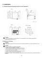
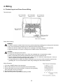
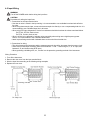
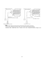
1
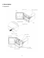
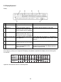
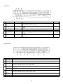
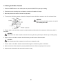
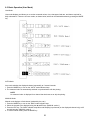
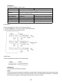
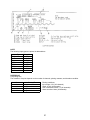
User's Manual
RCR-3000
Hybrid Recorder
Multipoint Type Recorder
TEMPCO Electric Heater Corporation
607 N. Central Avenue
Wood Dale, IL 60191-1452 USA
Tel:
630-350-2252
800-323-6859
Fax:
630-350-0232
website: http://www.tempco.com
Copyright © 2003, Tempco Electric Heater Corporation, all rights reserved.
Warning/Caution Symbol
This symbol calls attention to an operating procedure, practice, or the like which, if not correctly performed or adhered
to, could result in personal injury (warning) or damage to or destruction of part or all of the product and system (caution).
Do not proceed beyond a warning or caution symbol until the indicated conditions are fully understood and met.
Information in this user's manual is subject to change without notice.
Copyright © 2003, Tempco Electric Heater Corporation, all rights reserved. No part of this publication may be
reproduced, transmitted, transcribed or stored in a retrieval system, or translated into any language in any form by any
means without the written permission of Tempco Electric Heater Corporation.
Safety Guidelines
Be sure to observe the following warnings and cautions as well as those
found in the text in order to insure safety when handling this instrument.
WARNINGS
General
Before working with the wiring, fuse, or inside the instrument (including removal of the main unit), be sure to
disconnect the instrument from the main power source in order to prevent an electrical shock.
Protective Grounding
1) In order to prevent an electric shock, be sure to provide protective grounding prior to turning on the instrument.
2) Do not cut the protective grounding wire or disconnect protective grounding.
Power Source
1) Make sure that the voltage of the supply source conforms to the supply voltage specified for this instrument.
2) Attach the protective cover before turning on the instrument.
Fuse
1) In order to prevent a fire, use only the specified fuse.
2) Do not short-circuit the fuse holder.
Working Environment
Do not operate this instrument in an environment where it is exposed to a combustible, explosive, or corrosive gas,
or water or steam.
Input and Output Wiring
Turn off the power before connecting the input and output wiring.
CAUTIONS
Input and Output Wiring
Do not use empty terminals for purposes such as relaying, etc.
Inside of Instrument
Do not touch the switches, etc. inside this instrument. Also, do not replace the main unit or printed circuit boards. If
this is ignored, the functioning of the instrument cannot be guaranteed. Be sure to contact your sales representative.
Transportation
When transporting this instrument or equipment with this instrument incorporated, take proper preventive measures
to insure that the door does not open and that the main unit and the inner module will not fall out. (Reinstall the
shipping screws, etc.)
Instruction Manual
1) Make sure that this manual is delivered to the end user.
2) Be sure to read this manual prior to handling this instrument.
3) If you have any questions regarding this manual, or if you find any errors or omissions, contact your sales representative.
4) After reading this manual, keep it near the instrument.
5) If this manual is incorrectly collated, has missing pages, or is lost or stained, contact your sales representative.
Maintenance
Only Tempco service people or persons authorized by Tempco are allowed to remove and disassemble the main unit
and printed circuit boards.
Disposal and Cleaning
1) Dispose of replaced batteries properly.
2) Do not incinerate plastic maintenance parts and replacement parts; a harmful gas may be produced.
3) Use a dry cloth to clean the surface of this instrument.
4) Do not use any organic solvent.
5) Turn off the power when cleaning the instrument.
3
CONTENTS
1. Introduction
1-1
1-2
1-3
1-4
1-5
1-6
Checking the Accessories . . . . . . . . . . . . . . . . . . . . . . . . . . . . . . . . . . . . . . . . . . . . . . . . . . . . . . . . .
Removing Shipping Screws and Cushion . . . . . . . . . . . . . . . . . . . . . . . . . . . . . . . . . . . . . . . . . . . . .
Checking the Type and Specifications . . . . . . . . . . . . . . . . . . . . . . . . . . . . . . . . . . . . . . . . . . . . . . . .
Temporary Storage . . . . . . . . . . . . . . . . . . . . . . . . . . . . . . . . . . . . . . . . . . . . . . . . . . . . . . . . . . . . . .
Indication Card . . . . . . . . . . . . . . . . . . . . . . . . . . . . . . . . . . . . . . . . . . . . . . . . . . . . . . . . . . . . . . . . .
Features . . . . . . . . . . . . . . . . . . . . . . . . . . . . . . . . . . . . . . . . . . . . . . . . . . . . . . . . . . . . . . . . . . . . . .
.
.
.
.
.
.
.
.
.
.
.
.
.
.
.
.
.
.
.
.
.
.
.
.
6
7
8
8
8
8
2. Description
2-1
2-2
Appearance . . . . . . . . . . . . . . . . . . . . . . . . . . . . . . . . . . . . . . . . . . . . . . . . . . . . . . . . . . . . . . . . . . . . . . . 9
Display/Keyboard . . . . . . . . . . . . . . . . . . . . . . . . . . . . . . . . . . . . . . . . . . . . . . . . . . . . . . . . . . . . . . . . . . 10
3. Installation
3-1
3-2
Outside Dimensions Drawing and Panel Cutout Dimensions . . . . . . . . . . . . . . . . . . . . . . . . . . . . . . . . . . 12
Mounting to the Panel . . . . . . . . . . . . . . . . . . . . . . . . . . . . . . . . . . . . . . . . . . . . . . . . . . . . . . . . . . . . . . . 12
4. Wiring
4-1
4-2
4-3
Terminal Layout and Power Source Wiring . . . . . . . . . . . . . . . . . . . . . . . . . . . . . . . . . . . . . . . . . . . . . . . 14
Input Wiring . . . . . . . . . . . . . . . . . . . . . . . . . . . . . . . . . . . . . . . . . . . . . . . . . . . . . . . . . . . . . . . . . . . . . . 15
DI/Alarm Output Wiring (Option) . . . . . . . . . . . . . . . . . . . . . . . . . . . . . . . . . . . . . . . . . . . . . . . . . . . . . . . 17
5. Preparations for Operation
5-1
5-2
Setting the Chart Paper. . . . . . . . . . . . . . . . . . . . . . . . . . . . . . . . . . . . . . . . . . . . . . . . . . . . . . . . . . . . . . 18
Setting the Ribbon Cassette . . . . . . . . . . . . . . . . . . . . . . . . . . . . . . . . . . . . . . . . . . . . . . . . . . . . . . . . . . 20
6. Operation
6-1
6-2
6-3
Power-On . . . . . . . . . . . . . . . . . . . . . . . . . . . . . . . . . . . . . . . . . . . . . . . . . . . . . . . . . . . . . . . . . . .
Recording . . . . . . . . . . . . . . . . . . . . . . . . . . . . . . . . . . . . . . . . . . . . . . . . . . . . . . . . . . . . . . . . . . .
30-Channel Dot Printing Identification . . . . . . . . . . . . . . . . . . . . . . . . . . . . . . . . . . . . . . . . . . . . . .
Time Print and Date Print . . . . . . . . . . . . . . . . . . . . . . . . . . . . . . . . . . . . . . . . . . . . . . . . . . . . . . .
Basic Operation (User Mode) . . . . . . . . . . . . . . . . . . . . . . . . . . . . . . . . . . . . . . . . . . . . . . . . . . . .
AUTO Mode . . . . . . . . . . . . . . . . . . . . . . . . . . . . . . . . . . . . . . . . . . . . . . . . . . . . . . . . . . . . . . . . .
MANUAL Mode . . . . . . . . . . . . . . . . . . . . . . . . . . . . . . . . . . . . . . . . . . . . . . . . . . . . . . . . . . . . . . .
CLOCK Mode . . . . . . . . . . . . . . . . . . . . . . . . . . . . . . . . . . . . . . . . . . . . . . . . . . . . . . . . . . . . . . . .
CHART Mode . . . . . . . . . . . . . . . . . . . . . . . . . . . . . . . . . . . . . . . . . . . . . . . . . . . . . . . . . . . . . . . .
PRINT Mode . . . . . . . . . . . . . . . . . . . . . . . . . . . . . . . . . . . . . . . . . . . . . . . . . . . . . . . . . . . . . . . . .
Manual Logging Print . . . . . . . . . . . . . . . . . . . . . . . . . . . . . . . . . . . . . . . . . . . . . . . . . . . . . . . . . .
List Print . . . . . . . . . . . . . . . . . . . . . . . . . . . . . . . . . . . . . . . . . . . . . . . . . . . . . . . . . . . . . . . . . . . .
.
.
.
.
.
.
.
.
.
.
.
.
.
.
.
.
.
.
.
.
.
.
.
.
.
.
.
.
.
.
.
.
.
.
.
.
.
.
.
.
.
.
.
.
.
.
.
.
.
.
.
.
.
.
.
.
.
.
.
.
21
22
22
22
23
23
23
24
24
25
26
26
.
.
.
.
.
.
.
.
.
.
.
.
.
.
.
.
.
.
.
.
.
.
.
.
.
.
.
.
.
.
.
.
.
.
.
28
29
30
31
32
34
35
Setup Mode . . . . . . . . . . . . . . . . . . . . . . . . . . . . . . . . . . . . . . . . . . . . . . . . . . . . . . . . . . . . . . . . . . . .
Setting the Input Range. . . . . . . . . . . . . . . . . . . . . . . . . . . . . . . . . . . . . . . . . . . . . . . . . . . . . . . . . . . .
Setting Burnout Operation . . . . . . . . . . . . . . . . . . . . . . . . . . . . . . . . . . . . . . . . . . . . . . . . . . . . . . . . . .
Setting the Recording Scale Value . . . . . . . . . . . . . . . . . . . . . . . . . . . . . . . . . . . . . . . . . . . . . . . . . . .
Setting the Printout Unit Code . . . . . . . . . . . . . . . . . . . . . . . . . . . . . . . . . . . . . . . . . . . . . . . . . . . . . . .
Setting the Printing Function . . . . . . . . . . . . . . . . . . . . . . . . . . . . . . . . . . . . . . . . . . . . . . . . . . . . . . . .
Setting the Alarm Hysteresis Width . . . . . . . . . . . . . . . . . . . . . . . . . . . . . . . . . . . . . . . . . . . . . . . . . . .
Setting the DI Function, Communication Rate, etc. . . . . . . . . . . . . . . . . . . . . . . . . . . . . . . . . . . . . . . .
Display Unit Test Mode . . . . . . . . . . . . . . . . . . . . . . . . . . . . . . . . . . . . . . . . . . . . . . . . . . . . . . . . . . . .
.
.
.
.
.
.
.
.
.
.
.
.
.
.
.
.
.
.
37
38
40
41
44
44
46
47
50
7. Setting
7-1
7-2
7-3
7-4
7-5
7-6
7-7
Setting Range . . . . .
Unlocking the Keys .
Date/Time . . . . . . . .
Chart Speed . . . . . .
Logging Print. . . . . .
Dot Print Skip . . . . .
Alarm . . . . . . . . . . .
.
.
.
.
.
.
.
.
.
.
.
.
.
.
.
.
.
.
.
.
.
.
.
.
.
.
.
.
.
.
.
.
.
.
.
.
.
.
.
.
.
.
.
.
.
.
.
.
.
.
.
.
.
.
.
.
.
.
.
.
.
.
.
.
.
.
.
.
.
.
.
.
.
.
.
.
.
.
.
.
.
.
.
.
.
.
.
.
.
.
.
.
.
.
.
.
.
.
.
.
.
.
.
.
.
.
.
.
.
.
.
.
.
.
.
.
.
.
.
.
.
.
.
.
.
.
.
.
.
.
.
.
.
.
.
.
.
.
.
.
.
.
.
.
.
.
.
.
.
.
.
.
.
.
.
.
.
.
.
.
.
.
.
.
.
.
.
.
.
.
.
.
.
.
.
.
.
.
.
.
.
.
.
.
.
.
.
.
.
.
.
.
.
.
.
.
.
.
.
.
.
.
.
.
.
.
.
.
.
.
.
.
.
.
.
.
.
.
.
.
.
.
.
.
.
.
.
.
.
.
.
.
.
.
.
.
.
.
.
.
.
.
.
.
.
.
.
.
.
.
.
.
.
.
.
.
.
.
.
.
.
.
.
.
.
.
.
.
.
.
.
.
.
.
.
.
.
.
.
.
.
.
.
.
.
.
.
.
.
.
.
.
.
.
.
.
.
.
.
.
.
.
.
.
.
.
.
.
.
.
.
.
.
.
.
.
.
.
.
.
.
.
.
.
.
.
.
.
.
.
.
.
.
.
.
.
.....
.....
.....
.....
.....
.....
.....
.
.
.
.
.
.
.
.
.
.
.
.
.
.
.
.
.
.
.
.
.
.
.
.
.
.
.
.
.
.
.
.
.
.
.
.
.
.
.
.
.
.
8. Setup
8-1
8-2
8-3
8-4
8-5
8-6
8-7
8-8
8-9
9. Maintenance
9-1
9-2
9-3
Daily Inspections. . . . . . . . . . . . . . . . . . . . . . . . . . . . . . . . . . . . . . . . . . . . . . . . . . . . . . . . . . . . . . . . . . . 51
Maintenance and Servicing . . . . . . . . . . . . . . . . . . . . . . . . . . . . . . . . . . . . . . . . . . . . . . . . . . . . . . . . . . . 51
Replacing the Drive Cable. . . . . . . . . . . . . . . . . . . . . . . . . . . . . . . . . . . . . . . . . . . . . . . . . . . . . . . . . . . . 53
4
10. Calibration
10-1
10-2
10-3
10-4
10-5
10-6
10-7
Calibration Mode. . . . . . . . . . . . . . . . . . . . . . . . . . . . . . . . . . . . . . . . . . . . . . . . . . . . . . . . . . . . . . . .
Adjusting the Needle . . . . . . . . . . . . . . . . . . . . . . . . . . . . . . . . . . . . . . . . . . . . . . . . . . . . . . . . . . . . .
Range Adjustment 1 . . . . . . . . . . . . . . . . . . . . . . . . . . . . . . . . . . . . . . . . . . . . . . . . . . . . . . . . . . . . .
Range Adjustment 2 . . . . . . . . . . . . . . . . . . . . . . . . . . . . . . . . . . . . . . . . . . . . . . . . . . . . . . . . . . . . .
Reference Contact Compensation Adjustment . . . . . . . . . . . . . . . . . . . . . . . . . . . . . . . . . . . . . . . . . .
Setting Input Primary Conversion . . . . . . . . . . . . . . . . . . . . . . . . . . . . . . . . . . . . . . . . . . . . . . . . . . .
Using the Tie Port . . . . . . . . . . . . . . . . . . . . . . . . . . . . . . . . . . . . . . . . . . . . . . . . . . . . . . . . . . . . . . .
.
.
.
.
.
.
.
.
.
.
.
.
.
.
.
.
.
.
.
.
.
56
57
58
60
63
64
65
11. Troubleshooting
11-1 Troubleshooting . . . . . . . . . . . . . . . . . . . . . . . . . . . . . . . . . . . . . . . . . . . . . . . . . . . . . . . . . . . . . . . . . . . 66
11-2 Self Diagnostic Function . . . . . . . . . . . . . . . . . . . . . . . . . . . . . . . . . . . . . . . . . . . . . . . . . . . . . . . . . . . . . 70
12. Specifications
12-1
12-2
12-3
12-4
Common Specifications . . . . . . . . . . . . . . . . . . . . . . . . . . . . . . . . . . . . . . . . . . . . . . . . . . . . . . . .
Specifications of Multipoint Type Recorder. . . . . . . . . . . . . . . . . . . . . . . . . . . . . . . . . . . . . . . . . .
Standard Setting Functions . . . . . . . . . . . . . . . . . . . . . . . . . . . . . . . . . . . . . . . . . . . . . . . . . . . . .
Optional Functions . . . . . . . . . . . . . . . . . . . . . . . . . . . . . . . . . . . . . . . . . . . . . . . . . . . . . . . . . . .
5
.
.
.
.
.
.
.
.
.
.
.
.
.
.
.
.
.
.
.
.
.
.
.
.
72
73
75
75
1. Introduction
1-1 Checking the Accessories
Upon delivery of this instrument, unpack and check its accessories and appearance. If there are any accessories
missing or if the unit appears to be damaged, contact your sales representative.
The following accessories should be included:
1. Storage box (for parts 2 through 7)
2. Lubricant oil
3. Allen or L-wrench
4. Fuse (rating: 2A)
5. Chart paper
6. Ribbon cassette
7. Mounting brackets (2)
8. Instruction manual (this manual)
6
1-2 Removing Shipping Screws and Cushion
This instrument is protected against shocks and vibrations during transport by shipping screws and a cushion. Remove
them before using the instrument.
CAUTION
1. The instrument cannot record or print with the cushion attached.
2. When installing in the panel, leave the shipping screws in place to protect the main unit.
Removing the shipping screws
1. Open the door. (It opens to the left.)
2. Remove the two shipping screws. The main unit can now be drawn out.
CAUTION
The shipping screws are required when transporting the instrument, either alone or incorporated into other
equipment, or when repacking it. Be sure to put them in the screw storage holes (just below the shipping screw
holes).
Removing the cushion
1. While pressing down on the unlocking lever located on the lower right part of the unit, hold the draw-out handle and
gently pull the main unit towards you until it stops.
2. Remove the printer cushion from the printer.
CAUTION
The printer cushion is required when transporting the instrument, either alone or incorporated into other
equipment, or when repacking it. Be sure to store it someplace safe for later use.
7
1-3 Checking the Type and Specifications
A name plate, which lists the type, etc., is affixed to the right side of the main unit. Make sure that this instrument
matches the specifications you requested. Also, make sure that the scale plate and the type of input are as specified.
1-4 Temporary Storage
When storing the instrument temporarily, remove the ribbon cassette from the main unit. (See section 5-2)
When storing the instrument, whether alone or incorporated into other equipment, store it in the following environment.
• A place
• A place
• A place
• A place
• A place
• A place
with little dust.
that is not exposed to combustible, explosive, or corrosive gasses (SO2, H2S, etc.).
free from vibrations or shocks.
that is not exposed to water, steam, or high humidity (95% RH or more).
that is not exposed to direct sunshine or high temperatures (50°C or more).
that is not exposed to extremely low temperatures (-20°C or lower).
CAUTION
Storage in a poor environment may damage the appearance, functioning, and service life of the instrument.
1-5 Indication Card
An indication card has been affixed to the door prior to delivery. If you replace it with an acrylic plate, etc., make sure the
replacement complies with the following recommended dimensions: 205±0.5mm(W) x 60mm(H) x 2mm or less (thick).
CAUTION
If the replacement indication card is larger than the recommended dimensions, it may break the door or its
mounting.
1-6 Features
The RCR-3000 Hybrid Recorder has digital recording capabilities such as list printout, log printout, date printout, and
alarm printout, in addition to conventional analog recording capabilities. A variety of options are also available to meet a
wide array of needs.
Features
• Non-contacting
A non-contact electromagnetic potentiometer is used for position detection, and a high-voltage resistant photoMOS relay for input switching, creating longer life and easier maintenance for each block.
• Free power source applicable worldwide
A free power source available for 85–264VAC is used.
• Capable of mixing TC, mV, V, and RTD inputs
Each channel is independently capable of accepting TC, mV, V, or RTD inputs.
• Abundant on-board options
Available with a variety of options such as communication capability (RS-232/RS-422), 5 DIs, and 8 relay
outputs to allow high system flexibility.
8
2. Description
2-1 Appearance
9
2-2 Display/Keyboard
Display
No.
Name
Description
Remarks
1 Mode indicator lamps The lamp for the selected user mode For the user mode, see section 6-3.
is lit.
2 Display (1)
Displays the channel number or
The display changes depending on the mode.
setting item name. When an alarm
occurs, the alarm value is displayed.
3 Display (2)
Displays the measured value,
For the error codes (self diagnosis), see section 11-2.
various set values, date, time, etc.
When an error occurs, it is displayed.
4 Alarm indicator lamps. The channel number corresponding
to the alarm is lit.
For the alarm types, see section 7-7. The number of
alarm indicator lamps depends on the number of input
channels.
5 KEY LOCK lamp
Indicates whether the keys are
For the key lock state, see section 7-2.
locked (lit when the keys are locked).
6 RUN/STOP lamp
Lit when recording is running, unlit
when it is stopped. Blinks when
initializing the data.
When unlit (STOP mode), recording and data
sampling are not performed. The display value from
just before stopping is held.
Since displays (1) and (2) are 7-segment LED displays, the alphabet is symbolized for display. See the following table
for examples.
Display
A
B
C
D
E
F
G
H
1
J
K
L
M
N
Alphabet
A
B
C
D
E
F
G
H
I
J
K
L
M
N
Display
O
P
R
S
T
u
U
H
Y
=
Alphabet
O
P
R
S
T
U
V
X
Y
Z
/
γ
Q
Uppercase and lowercase letters are not distinguished.
10
W
User Mode
No. Indicator Lamp
Mode
1
AUTO
AUTO mode
2
MAN
3
CLOCK
Outline of Function
Details
Sequentially displays the measured values for all channels in
Section 6-3
synchronization with dot printing.
MANUAL mode Displays the measured value for the channel selected by the S or Section 6-3
T keys.
CLOCK mode Displays and alters the year, month, day, and time.
Section 6-3
4
5
CHART
PRINT
CHART mode
PRINT mode
6
ALARM
ALARM mode
Displays and sets the chart paper feed rate.
Section 6-3
Starts manual logging print and list print, and sets the time log and Section 6-3
dot skip.
Displays the alarm setting state, sets the alarm value, and sets the Section 7-7
alarm output.
Operation Keys
No.
Key
Key Function
1 MODE
Selects the user mode
2 PGM
Switches to the parameter setting enable state (input mode).
3 W
Moves backwards through the selection items when setting a parameter.
Moves the selected digit to the left in input mode.
4 S
Counts up an item or numerical value.
T
Counts down an item or numerical value.
5 ENT
Determines the selected numerical value or item when setting a parameter.
Moves the selected digit to the right in input mode.
6 FEED
Feeds the chart paper quickly
7 RUN/STOP
Starts or stops recording.
11
3. Installation
3-1 Outside Dimensions Drawing and Panel Cutout Dimensions
CAUTION
For safety and maintenance of the instrument, it is recommended to secure spacings larger than the
parenthesized dimensions per unit.
3-2 Mounting to the Panel
WARNING
Do not install the instrument in a place exposed to a combustible, explosive, or corrosive gas (SO2, H2S, etc.).
CAUTION
Install the instrument in the following environment
1. A place where the temperature is consistent.
2. A place where the temperature is normal (77°F/25°C or so).
3. A place exposed to as little mechanical vibration as possible.
4. A place with as little dust as possible.
5. A place affected by electromagnetic fields as little as possible.
6. A place not directly exposed to high radiant heat.
Humidity has an effect on chart paper and ink. Use the instrument in a humidity range of 35–85%RH (60%RH is
optimum).
12
Mounting Panel
1. A steel plate not thinner than 3mm is recommended for the mounting panel.
2. The maximum thickness for the mounting panel is 15mm.
Inclination
1. Install the instrument horizontally.
2. The inclination of the instrument should be 0° at the front and no more than 30° at the back.
CAUTION
Be sure to fix the main unit with the shipping screws prior to mounting for safety and protection of the main unit.
1. Fix the main unit with the shipping screws.
2. Insert the instrument through the front of the panel.
3. Insert the claws of the mounting brackets into the square holes on either side of the case.
4. Tighten the screws on the mounting brackets with a regular screwdriver. Do not use excessive force when
tightening the screws; it would distort the case into contact with the main unit and door.
5. After installing the instrument, put the transportation screws back in the screw storage holes.
13
4. Wiring
4-1 Terminal Layout and Power Source Wiring
Terminal Layout
Power Source Wiring
WARNING
1. In order to prevent an electric shock, be sure to provide protective grounding prior to turning on the instrument.
2. Do not cut the protective grounding wire or disconnect protective grounding.
3. Make sure that the voltage of the supply source conforms to the supply voltage for the instrument.
4. Attach the protective cover prior to turning on the POWER switch of the instrument.
CAUTION
Precautions for wiring the power source
1. For the wires for the power source, use a 600V vinyl insulated wire or its equivalent or above.
2. Attach a press-fitting terminal with insulated sleeve to the end of the electrical wire.
3. Provide a Class-3 (grounding resistance value: 100Ω or less, min. diameter of grounding wire: 1.6mm) or
above connection for the protective grounding terminal.
4. If the grounding wire is shared with another instrument, there may be an effect caused by noise from the
grounding wire. It is not recommended to share the grounding wire with another instrument.
Wiring Procedure
1. Turn off the POWER switch of the instrument.
2. Remove the protective cover from the power source terminal block.
3. Connect the power source wires as shown. Connect the non-grounding
side of the power source to terminal 2.
4. Put the protective cover back in place.
5. Make sure that protective grounding is properly provided.
14
4-2 Input Wiring
WARNING
Turn off the POWER switch before wiring the input lines.
CAUTION
Precautions for wiring the input lines.
1. Precautions for the input electrical wire.
• See that no noise is mixed in the input wiring. It is recommended to use a shielded or twisted wire effective
for noise.
• When using thermocouple input, connect the thermocouple wire directly or use a compensating lead wire. It is
recommended to use a shielded input line in all cases.
• When using RTD input, dispersion of 3-wire line resistance should be less than the values mentioned below.
For PT100, JPT100: 50mΩ or less
For PT50, Cu10Ω: 10mΩ or less
• When it is likely to be affected by induction noise, especially when wiring near a high-frequency power
source, it is recommended to use a shielded twisted wire.
• Attach a press-fitting terminal with insulated sleeve to the end of the electrical wire.
2. Precautions for wiring.
• The wiring between the instrument and the measurement point should be kept away from the power circuit.
• Short-circuit unused input terminals. (Short-circuit between “+” and “-” when using mV, V, or TC input, and
between A, B, and b when using RTD input.)
• When grounding a shielding wire, etc., connect it to the protective grounding terminal of the instrument.
Wiring Procedure
1. Turn off the instrument.
2. Remove the rear cover from the input terminal block.
3. Wire the input lines according to the following wiring examples.
4. Replace the rear cover.
15
NOTE
• Attach a shunt resistor to the input block of the instrument when using DC current input.
• Input accuracy is affected by the shunt resistor. Use a resistor with the following properties:
Resistance: 100Ω Rated Power: 1/8W Tolerance: ±0.1% or less Temperature Coefficient: ±50ppm or less
16
4-3 DI/Alarm Output Wiring (Option)
WARNING
1. Be sure to turn off the power before wiring.
2. If a power source has been connected to the alarm output, turn off that power source as well.
CAUTION
Precautions for wiring the DI/alarm output.
Precautions for wiring the DI.
1. The DI inputs incorporate the drive power source. Do not apply an outside voltage to a DI input terminal.
2. The DI input contacts can withstand a voltage of 50VDC, 16mA or more, with a load of 20Ω or less (wiring
resistance included).
3. Do not use unused terminals as relay terminals.
Precautions for wiring the alarm output.
1. Alarm output contact capacity is as follows:
250VAC: 3A maximum (resistance load)
30VDC: 3A maximum (resistance load)
125VDC: 3A maximum (resistance load), 0.1A maximum
L/R=40ms maximum (induction load)
2. Attach an anti-surge circuit (surge suppressor, etc.) to the output terminals as required.
3. Attach a press-fitting terminal with insulated sleeve to the end of the electrical wire.
4. Keep the alarm output wiring away from the input wiring.
NOTE
The DI/DO option consists of 5 digital input contacts and 8 alarm relay output contacts.
17
5. Preparations for Operation
5-1 Setting the Chart Paper
CAUTION
Use our standard chart paper for proper recording.
1. Press the POWER button to turn off the power or press the RUN/STOP key to stop recording.
CAUTION
If the chart holder is lowered while the recorder is running, the printer may be damaged.
2. Open the door and remove the chart holder. To remove it, hold both ends and pull upward.
3. Hold the levers located on either side of the chart holder to unlock it and incline the chart holder forward.
4. Unlock the chart cover on both sides as shown to open it. When replacing the chart paper, remove the used chart paper.
5. Fan the new chart paper before inserting it.
NOTE
If the chart paper sticks at the perforations, it may not feed properly. Be sure to fan it.
6. Unfold about three pages of the chart paper. With the square holes on the left side, position it in the paper housing so
it will be drawn out properly, as shown below.
18
NOTE
Set the chart paper over the shaft and make sure that the holes are set properly.
7. Make sure that the chart paper is bent downward and that the holes are properly aligned with the teeth on the
sprocket drum. Close the chart cover until it locks into place. Next, holding the levers of the chart holder with both
hands, pull up the holder. Move the levers slightly side to side and up and down to make sure that the chart holder is
correctly attached to the main unit.
8. Wind the chart paper, aligning its holes with the teeth on the sprocket drum, and return the chart holder to its original
position. Make sure that the holes in the chart paper are properly engaged with the teeth of the sprocket drum.
9. Before running the recorder, press the FEED key with the power turned on to eliminate any play in the chart paper
from between the gears of the chart holder.
NOTE
1. Be sure to feed about 4 to 6 pages of the chart paper before running the recorder.
2. If the chart paper does not feed properly when the FEED key is pressed, check to make sure the paper is set
properly.
REFERENCE
There is a triangular mark (U) on the chart holder to indicate 20mm before
the dot printing position. This can be used to adjust the print timing.
19
5-2 Setting the Ribbon Cassette
1. Press the POWER button to turn off the power or press the RUN/STOP key to stop recording.
2. Press down on the unlocking lever and draw the internal unit forward until it stops.
3. Move the printer to the center of the main unit (by hand).
4. To remove the old ribbon cassette, release the clamp and remove the ribbon cassette to the side as shown below.
CAUTION
When removing the ribbon cassette, be careful
not to damage the cable.
5. Turn the knob on the new ribbon cassette counterclockwise (as indicated on the cassette) to eliminate any slack in
the ribbon.
CAUTION
If the knob on the ribbon cassette is turned in the wrong direction (clockwise) the ribbon may not feed properly.
6. Align the holes in the ribbon cassette with the bracket pins and insert the ribbon cassette.
CAUTION
When inserting the ribbon cassette, be careful not to damage the cable.
7. Turn the knob on the ribbon cassette counterclockwise again to eliminate any slack in the ribbon.
8. Make sure that the ribbon cassette is properly seated and that the ribbon is properly set in the printer.
9. Push the main unit back into the case until it comes to a stop.
20
6. Operation
6-1 Power On
WARNING
Before turning on the power, make sure that the supply voltage meets the instrument specifications and that the
instrument is properly grounded.
CAUTION
Precautions on the wiring.
Before turning on the power, make sure that the chart paper is set in the chart holder. If the printer is activated
with no chart paper set, the sprocket drum may be damaged.
To turn on the power, open the front door and press the POWER switch at the bottom center of the unit (inside the door).
When the power is turned on, characters will appear on the front display. The instrument will be ready to run in about 5
seconds, including the initialization screen. If the POWER switch is pressed while the power is on, the power will turn off.
Conditions After Initialization Screen
Display mode
AUTO
RUN/STOP key
RUN
Printout data
All printout and analog data prior to
power-off are cleared.
Alarm and self-diagnostics Alarm indications and outputs prior to
power-off are not reset.
Key lock
Locked state
NOTE
1. If there is a power failure, the display will be reinitialized when power is recovered, resulting in the abovementioned initial conditions.
2. The printout data are cleared during initialization. If the power is turned off during printout, printout operation
does not continue, even after power has been restored.
21
6-2 Recording
30-Channel Dot Printing Identification
This instrument identifies channels by means of a 6-color ink ribbon and suffix printout.
CAUTION
In order to protect the chart paper, dot printing is not performed if the distance between the previous dot printing
position and the next one for a given channel is less than 0.2mm in the chart paper feed direction or less than
0.5mm in the scale direction.
30-Channel Dot
Color
Purple
Red
Black
Green
Blue
Brown
Printing Identification Table
Dot Printing Channel
Ch. 1, 7, 13, 19, 25
Ch. 2, 8, 14, 20, 26
Ch. 3, 9, 15, 21, 27
Ch. 4, 10, 16, 22, 28
Ch. 5, 11, 17, 23, 29
Ch. 6, 12, 18, 24, 30
Time Print and Date Print
For more information on the time print and date print functions, see
section 8-6.
NOTE
Printing is synchronized with chart paper feed.
Time print and date print depend on the chart paper feed rate.
Chart Paper Feed Rate
9mm/h or less
10 to 29mm/h
30 to 100mm/h
101mm/h or more
Time Printing Timing
Description
No printout
Printed every 6 hours
Printed every other hour (even-numbered hours)
Printed every hour
Date Printing Timing
Chart Paper Feed Rate
Description
4mm/h or less
No Printout
5mm/h or more
Printed at specified time
22
6-3 Basic Operation (User Mode)
User Mode
User mode displays and allows you to set the measured values, time, chart paper feed rate, and alarms required for
daily maintenance. There are six user modes, as shown below, which can be switched between by pressing the MODE
key.
AUTO Mode
Auto mode switches the displayed channel sequentially at 5 second intervals.
1. Press the MODE key to turn on the “AUTO” mode indicator lamp.
2. The measured value is automatically switched in synchronization with dot printing.
NOTE
No measured value is displayed for a channel that has been set to skip dot printing.
MANUAL Mode
Manual mode displays a fixed channel (selected by the user).
1. Press the MODE key to turn on the “MAN” mode indicator lamp.
2. Select the channel to be displayed using the S and T keys. (MANUAL mode 1)
3. Press the ENT key. The “MAN” indicator lamp blinks and sampling is performed (on the displayed channel only) at 0.5
second intervals. (MANUAL mode 2)
4. To cancel manual mode, press the MODE key.
23
REFERENCE
Operations in MANUAL modes 1 and 2
Function
MANUAL Mode 1
Display 1
MANUAL Mode 2
Displays the channel number
Display 2
Displays the measured value, or “SKIP” if the selected channel has
been set to skip dot printing.
Dot printing
Performed
Not performed
Alarm judgement
Performed
Performed only for the display channel
Time log printout
Performed
Not performed
Self diagnosis
Performed
Not performed
Display sampling cycle
Synchronized with dot printing
0.5 second cycle
CLOCK Mode
Clock mode displays the current year, month, day, and time.
1. Press the MODE key to turn on the “CLOCK” mode indicator lamp.
2. Use the S and T keys to display each item.
CHART Mode
Chart mode displays and sets the current chart speed.
REFERENCE
The chart speed is initially set at 30mm/h.
NOTE
In order to protect the chart paper, dot printing is not performed if the distance between the previous dot printing
position and the next one for a given channel is less than 0.2mm in the chart paper feed direction. To make sure
all the dots can be printed, the chart paper feed rate must be 15mm/h or higher.
24
When chart speed selection (option) has been set, the display is as follows.
REFERENCE
The 1st chart speed is initially set at 30mm/h; the 2nd chart speed is initially set at 60mm/h.
PRINT Mode
Print mode starts manual logging print and list print (printout of setting parameters).
1. Press the MODE key to turn on the “PRINT” mode indicator lamp.
2. The display screen will be as follows.
REFERENCE
Printing priority
When multiple print jobs are started simultaneously, the one with the highest priority according to the following
list will be performed first, followed by the one with the next-highest priority (upon completion of the first job).
WHigher
LowerX
List Print > Alarm On Print > Alarm Recovery On Print > Logging Print > Date Print > Time Print
25
Manual Logging Print
NOTE
1. Printing is performed only when the printer is running.
2. Since log printing is asynchronous with chart paper feed, dot printing and data sampling are not performed.
3. To force log printing to stop, press the RUN/STOP key to put the recorder in STOP mode. Note that doing this
will also clear all other waiting data.
REFERENCE
Log printing time
Logging print time differs depending on the number of channels, printing contents, and whether an alarm is
issued.
No. of Channels
6
12
24
30
Log Printing Time
Approx. 1min. 15sec.
Approx. 2min. 20sec.
Approx. 4min. 25sec.
Approx. 5min. 30sec.
Printing conditions
Measured value: 0.0°C for all channels
List Print
NOTE
1. Printing is performed only when the printer is running.
2. Since list printing is asynchronous with chart paper feed, dot printing and data sampling are not performed.
3. To force list printing to stop, press the RUN/STOP key to put the recorder in STOP mode. Note that doing this
will also clear all other waiting data.
26
NOTE
The following input types are printed in abbreviations.
Input Type
Abbreviation
PR40-20
PR4
Au-Fe
AuF
PLII
PL2
JPT100
JPT
PT100
PT1
PT50
PT5
Cu10Ω at 0°C
CU1
Cu10Ω at 25°C
CU2
REFERENCE
List printing time
The duration of list print depends on the number of channels, printing contents, and the alarm condition.
No. of Channels
6
12
24
30
List Printing Time
Approx. 4minutes
Approx. 6minutes
Approx. 11minutes
Approx. 14minutes
Printing conditions
Input range: 0–5V (All channels)
Scale: 0–100 (All channels)
Unit of measured values: °C (All channels)
Alarm set value: None (All channels)
27
7. Setting
7-1 Setting Range
The following table lists the settable items. The parameters will be set with the following values unless they were
specified otherwise when ordered.
NOTE
1. If a setting is changed, the initial value is lost and the new value will be retained, even if the power is turned off.
2. Items marked “Option” can only be set if they were specified as options when the instrument was ordered.
Settable Item
CLOCK mode
Date and time
CHART mode
Chart speed
1st rate
2nd rate
PRINT mode
Logging print
Logging print run
Logging print intervals
Printout start time
Dot print skip setting
NOTE: Set for each channel
ALARM mode
Alarm value setting
NOTE: The following alarm types
can be set for each channel.
(4 alarm types)
HH alarm
H alarm
L alarm
LL alarm
NOTE: Set for each channel
Alarm output setting
NOTE: One output can be set for
each alarm type for each channel.
User Mode Setting Parameters
Settable Range
Initial Setting
Year
Month
Day
Hour
Minute
1993 onward
01–12
01–31
00–23
00–59
Remarks
Current time
1–1800mm/h
1–1800mm/h
30mm/h
60mm/h
ON1 (Asynchronous)
ON2 (Synchronous)
OFF
10, 20, or 30 min., 1, 2, 3,
4, 6, 8, 12, or 24 hrs.
0–23
ON Prints dots
OFF Does not print dots
ON 2
-19999 to 99999
The decimal point position
and the unit corresponds
to those set in the setup.
Relays 1–8
OFF
6 hours
—
All channels ON
The start time can only be set if
the logging print intervals are 8
hours or more.
Common to all channels
HH: 0.0
H: 0.0
L: 0.0
LL: 0.0
OFF (All relays)
28
Option
Option
7-2 Unlocking the Keys
Key Lock State
When the instrument is in key lock state, the “KEY LOCK” lamp is lit.
REFERENCE
Key lock conditions
1. When the power is turned on and initialization is performed.
2. When no keys have been pressed for 3 minutes when the keys are unlocked.
Unlocking the Keys
To unlock the keys, press and hold the PGM and ENT keys simultaneously for about 3 seconds. The “KEY LOCK” lamp
will turn off and the keys will be unlocked.
REFERENCE
Key lock target data
1. Alarm set value, alarm output setting
2. Chart paper feed rate
3. Date/time settings
4. Logging print setting
5. Dot print skip setting
6. Setup data
7. Calibration
29
7-3 Date/Time
Follow steps 1 and 2, then see the example below to set the date and time.
1. Press the MODE key to turn on the “CLOCK” mode indicator lamp.
2. Press and hold the PGM and ENT keys simultaneously for about 3 seconds to unlock the keys.
30
7-4 Chart Speed
Follow steps 1 and 2, then see the example below to set the chart speed.
1. Press the MODE key to turn on the “CHART” mode indicator lamp.
2. Press and hold the PGM and ENT keys simultaneously for about 3 seconds to unlock the keys.
31
7-5 Logging Print
Follow steps 1 and 2, then see the example below to set Logging print.
1. Press the MODE key to turn on the “PRINT” mode indicator lamp.
2. Press and hold the PGM and ENT keys simultaneously for about 3 seconds to unlock the keys.
Display 2
ON1
ON2
OFF
Screen Name
Logging print run
(Chart paper force fed)
Function
Performs logging print. Once printing is initiated, the chart paper is fed
forcibly, including a line feed according to the printing format. Data sampling
is suspended during printing.
Logging print run
Performs logging print. Since printout is performed according to the set
(Chart paper feed synchronous) chart paper feed rate, analog recording is not suspended. To perform log
printing properly, it is necessary to set the chart paper speed higher than
the rates specified below.
Logging print cancelled
Does not perform log printout
32
Logging Print Example
NOTE
Logging print intervals
Display 2
Printout Intervals
10M 10 minutes: 00, 10, 20, 30, 40, and 50 of every hour
20M 20 minutes: 00, 20, and 40 of every hour
Start Time
Min. Chart Speed
Setting
for Logging Print*
Disallowed 144mm/h
Disallowed
72mm/h
Disallowed
48mm/h
Disallowed
24mm/h
2H 2 hours: 00, 02, 04, ... 22 hours
3H 3 hours: 00, 03, 06, ... 21 hours
Disallowed
12mm/h
Disallowed
8mm/h
4H 4 hours: 00, 04, 08, ... 20 hours
6H 6 hours: 00, 06, 12, and 18 hours
Disallowed
6mm/h
Disallowed
4mm/h
30M 30 minutes: 00 and 30 of every hour
1H 1 hour: Every hour
8H00 8 hours: Start time, start time+8, and start time+16 hours Allowed
Allowed
12H00 12 hours: Start time and start time+12 hours
4mm/h
24H00 24 hours: Daily start time
2mm/h
Allowed
*The minimum chart speed shows an example for a 12-Multipoint recorder.
33
2mm/h
7-6 Dot Print Skip
In this section, you can set the recorder to skip dot printing on a channel as follows.
1. Press and hold the PGM and ENT keys simultaneously for about 3 seconds to unlock the keys.
2. Press the MODE key to turn on the “PRINT” mode indicator lamp.
3. Use the S or T keys to display “SKIP”.
REFERENCE
Functioning of channel set for dot print skip
1. Does not perform dot printing.
2. Does not display a measured value in AUTO or MANUAL
modes.
3. Does not output an alarm.
4. Prints “*” for measured value in logging print.
NOTE
All of the channels cannot be set for dot print skip at the same
time. If they are, the display will blink and show the following
error message. At least one channel must be set to print.
34
7-7 Alarm
In this section, you confirm and set the alarms.
Screen Configuration
NOTE
In addition to setting the alarms by channel, they can be set in groups. There are six groups to choose from:
G0 (all channels), G1 (channels 1–6), G2 (channels 7–12), G3 (channels 13–18), G4 (channels 19–24), and G5
(channels 25–30). When confirming the set values, the data from the first channel in that group is displayed.
List of Alarm Setting Items
Display 1
Ex. Channel 1
01 HH
01 H
01 LL
01 L
Alarm
Description
Settable Range
HH alarm Activated when the measured value -19999 to 99999
NOTE: The decimal point
H alarm is higher than the alarm set value
position corresponds to the
L alarm
Activated when the measured value
position set in the setup data.
is lower than the alarm set value.
L alarm
NOTE
Alarms are outputted synchronously with dot printing.
35
REFERENCE
1. One alarm output can be set for each alarm item.
2. The same alarm output number can be selected for a different alarm type or for a different channel.
Set the alarm as shown in the example below.
<Example> Setting an HH alarm value of 1000.0 for channel 1 and assigning the alarm output to relay 1.
1. Press the MODE key to turn on the “ALARM” mode indicator lamp.
2. Press and hold the PGM and ENT keys simultaneously for about 3 seconds to unlock the keys.
3. Set the alarm value and alarm output relay number.
36
8. Setup
8-1 Setup Mode
In this section, you set the setup data (input range, burnout operation, scaling/recording scale, unit, printing function,
alarm hysteresis, DI function, communication rate/address) and conduct an operation test on the display.
NOTE
1. The setup data will have been set according to the specifications ordered.
2. If the setup data is altered, the change is permanent; the previous data will not be restored even if the
instrument is turned off.
Switching to Setup Mode
NOTE
1. In setup mode, the “AUTO” and “MAN” indicator lamps blink.
2. In setup mode, measurement and dot printing are not performed, but the chart paper will continue to be fed.
37
8-2 Setting the Input Range
In this section, you set the input range.
NOTE
In addition to setting the input range by channel, it can be set in groups. There are six groups to choose from:
G0 (all channels), G1 (channels 1–6), G2 (channels 7–12), G3 (channels 13–18), G4 (channels 19–24), and G5
(channels 25–30). When confirming the set values, the data from the first channel in that group is displayed.
38
Range Codes Table
Range Display
Code Symbol
001
MU 1
002
MU 2
003
MU 3
004
U 1
005
U 2
006
U 3
007
U 4
008
U 5
009
MA 010
R 1
011
R 2
012
S 013
B 014
K 1
015
K 2
016
K 3
017
K 4
018
K 5
019
K 6
020
K 7
021
K 8
022
E 1
023
E 2
024
E 3
025
E 4
026
E 5
027
E 6
028
E 7
029
E 8
030
J 1
Range Width
±10mV
±50mV
±200mV
±1V
±5V
±20V
0–5V
1–5V
4–20mA
R 0–1450°C
R 0–1760°C
S 0–1760°C
B 0–1830°C
K 0–100°C
K 0–700°C
K 0–900°C
K -200–100°C
K -200–400°C
K -200–650°C
K -200–1370°C
K 0–1000°C
E 0–150°C
E 0–400°C
E -200–500°C
E -200–600°C
E -200–900°C
E -200–250°C
E -200–400°C
E -200–700°C
J 0–150°C
Range
Code
031
032
033
034
035
036
037
038
039
040
041
042
043
044
045
046
047
048
049
050
051
052
053
054
055
056
057
058
059
060
39
Display
Symbol
J 2
J 3
J 4
J 5
J 6
J 7
T 1
T 2
T 3
T 4
G C N 1
N 2
PR4 u L AuF JPT 1
JPT 2
PT1 1
PT1 2
PT5 1
PT5 2
PT5 3
Cu1 Cu2 PL2 -
Range Width
J 0–500°C
J -200–650°C
J -200–300°C
J -200–500°C
J -200–900°C
J -200–750°C
T 0–150°C
T 0–400°C
T -200–350°C
T -200–400°C
G 0–2320°C
C 0–2320°C
N 0–900°C
N 0–1260°C
PR40-20 0–1880°C
U -200–400°C
L -200–900°C
Au-Fe 0–300°C
JPT100 at 0°C -50–100°C
JPT100 at 0°C -200–600°C
PT100 at 0°C -50–100°C
PT100 at 0°C -200–600°C
PT50 at 0°C
-50–100°C
PT50 at 0°C
-100–250°C
PT50 at 0°C
-200–550°C
Cu10Ω at 25°C -50–200°C
Cu10Ω at 0°C -50–200°C
PLII
0–1360°C
8-3 Setting Burnout Operation
When using mV input (with the exception of 200mV range) or thermocouple input, you can set burnout analog recording
operation in case the input is disconnected.
<Example> Setting burnout high for channel 5.
40
8-4 Setting the Recording Scale Value
In this section, you set the zero and span points for the recording scale and the decimal point position for the display
and printout. When scaling is required for the mV, V, or mA meter, set it in this mode. Also set in this mode when using
zone recording.
1. Recording scale setting screen configuration for mV, V, or mA meter.
NOTE
When not using zone recording, it is unnecessary to set the position zero and position span points.
41
<Example> Changing 0–5V input range with 0.0–500.00 display/recording range to 1–5V input range with 0.00 to 100.00
display/recording range for channel 2.
NOTE
The decimal point position for display and printout is determined here.
42
2. Recording scale setting screen configuration for thermocouple or RTD input.
NOTE
When not using zone recording, it is unnecessary to set the position zero and position span points.
<Example> Changing the setting for channel 1 from 0–1,760°C to 1,000–1,600°C.
43
8-5 Setting the Printout Unit Code
In this section, you set the printout unit code for the measured values according to the unit codes list below.
<Example> Changing the unit for channel 1 from °C (unit code 231) to mV (unit code 313).
Unit Code Symbol
231
°C
303
mA
310
V
313
mV
8-6 Setting the Printing Function
In this section, you set whether or not the recorder provides time print, date print, alarm on print, and alarm recovery on print.
44
Setting Time Print Operation
When altering the setting, press the PGM, S, and ENT keys in that order. The initial value is “ON”.
Setting Date Print Operation
The initial value in “00 ON”. Which hour the date starts printing on can also be set with this function.
<Example> Setting the date to print at 5:00 am.
Setting Alarm On Print
When altering the setting, press the PGM, S, and ENT keys in that order. The initial value is “OFF” unless otherwise
specified.
Setting Alarm Recovery On Print
When altering the setting, press the PGM, S, and ENT keys in that order. The initial value is “OFF” unless otherwise
specified.
NOTE
Printout follows the printing priority in section 6-3. This print can wait one dot during its execution.
45
8-7 Setting the Alarm Hysteresis Width
In this section, you set the hysteresis width at the time of alarm recovery judgment. This setting applies to all channels.
<Example> Changing the alarm hysteresis width from 0.5 to 0.2.
REFERENCE
The initial value is “0.5” unless otherwise specified.
NOTE
The alarm hysteresis width is provided for the full scale of the digital display value.
46
8-8 Setting the DI Function, Communication Rate, Etc.
In this mode, you set the DI1–DI3 functions, fail output relay, communication rate, and communication local address.
Setting the DI1 Function
You can select the “chart paper start/stop” function for the first DI.
DI1 State
Chart Paper Feed State
ON
Start state
OFF
Stop state (indication and dot printing provided)
NOTE
To use this function, the unit must have the “5DIs” option.
47
Setting the DI2 Function
You can select the “chart speed” function for the second DI.
DI2 State
ON
OFF
Chart Speed Selection
1st speed
2nd speed
NOTE
To use this function, the unit must have the “5DIs” option.
Setting the DI3 Function
You can select the “external logging print start” function for the third DI.
DI3 State
External Logging Print Start
OFF—>ON Starts logging print (synchronous printing)
NOTE
To use this function, the unit must have the “5DIs” option.
48
Setting the Fail Output Relay
When an error occurs inside the recorder, a relay is driven to output its status. This relay is relay 8; the relay number
cannot be altered. In this section, you set whether this function is on or off and the logic upon output.
Fail output relay operations by the settings described above are shown below. This example assumes that an individual
alarm output has been assigned to relay 8.
Setting the Communication Rate
You set the communication rate (bps). (This function requires communications options RS-232C or RS-422A.)
(Select from 19,200, 9,600, 4,800, 2,400, or 1,200bps.)
Setting the Communication Local Address
You set the local address. (This function requires the communications option RS-422A.)
(Setting range: 01 to 15.)
49
8-9 Display Unit Test Mode
In this mode, all the display LEDs are turned on as follows to diagnose hardware related troubles.
Display Test Method
50
9. Maintenance
9-1 Daily Inspections
Inspect the following items. If a problem is found, see section 11-1.
Inspection Items
Are recording and indication done properly?
• Is there a big error in the display value or the dot printing position?
• Is there any inappropriate dot printing?
• Is the dot printing or the printouts blurry?
• Is it printing the proper printout?
Is the chart paper feeding properly?
• Is the chart paper folded properly?
• Are the fed holes in the chart paper torn off or broken?
• Is the chart paper feeding at the correct rate?
Is there any unusual sound coming from the instrument?
Consumable Parts
1. Chart paper
2. Ribbon cassette
3. Lubricant (LAUNA 40 produced by NIPPON OIL or its equivalent)
4. Drive cable
‘5. Fuse (2A)
9-2 Maintenance and Servicing
Chart Paper
• When the chart paper is running out, a red mark appears on the right side of the chart paper. Replace it immediately.
CAUTION
1. If dot printing or printout is performed without any chart paper installed, ink may adhere to the sprocket drum,
or the printer and sprocket drum may be damaged. Do not print without the chart paper installed.
2. It is recommended to use our standard chart paper to insure proper recording.
REFERENCE
1. The total length of the chart paper is 23m.
2. If you pull out the main unit, you can check the remaining amount of chart paper through a window on the
right side of the unit.
Ribbon Cassette
• When recording with a ribbon, the dot printing color will start to fade out. To ensure clear recording, replace the ribbon
cassette as soon as possible when this starts to happen.
• Use ribbon cassettes within one year of purchase. Due to the evaporation of the ink, the printing color will start to fade
over time.
Replacement recommendation:
• After recording 3 rolls of chart paper. (3 months of continuous operation at normal temperature and humidity)
• About 6 months if operation is suspended after unpacking.
CAUTION
Never use a ribbon if the fiber is damaged. If printouts are performed more frequently, the ribbon will need to be
replaced more often.
51
Lubrication
In order to keep the instrument in good working order, check the mechanical moving parts periodically for oil shortage,
and lubricate them as required.
CAUTION
1. Lubricate periodically at the following intervals.
2. If you find a foreign substance in the instrument caused by oil contamination, remove it and lubricate.
3. Apply one or two drops of oil and wipe away any excess.
<Where to lubricate>
a. Printer shaft (quarterly)
b. Grooved shaft (quarterly)
c. Ribbon rocking gear and bearing (quarterly)
d. Sprocket drum bearing (yearly)
Fuse
It is recommended to replace the fuse every other year as preventive maintenance.
WARNING
When replacing the fuse, turn off the power and disconnect the instrument from the main power source. Be sure
to use the specified type of fuse (for fire prevention). Do not short-circuit the fuse holder.
Replacement procedure:
1. Turn off the power and disconnect the instrument from the main power source.
2. The fuse is on the rear of the instrument, next to the power terminal block on the lower right. Use a slotted
screwdriver to remove it.
3. Insert a new fuse.
52
Model
6CH
12CH
24CH
30CH
CAUTION
Logging print frequency and ribbon replacement intervals
If the ink ribbon is used longer than its service life, the ribbon fiber will be damaged, resulting in improper ribbon
feed and/or trouble printing. The life of the ribbon may be shortened depending on the logging print frequency.
The following table shows the relationship between printout frequency and ribbon replacement intervals. Check
the ribbon periodically for damage. If it is damaged or the fiber is loose, replace it, even if it is not due to be
replaced yet.
1. Printing life: 100,000 characters (120 million dots, 12 dots/character, average.)
2. Logging print frequency and ribbon replacement intervals
Normal number
Logging Print Intervals/Ribbon Replacement Intervals
of characters in
each log
10 min. 20 min. 30 min.
1hr.
2hrs.
3hrs.
4hrs.
6hrs.
8hrs. 12hrs. 24hrs.
printout
11 days 23 days 34 days 69 days 90 days
–>
–>
–>
–>
–>
–>
60 chars.
5 days 11 days 17 days 34 days 69 days 90 days
–>
–>
–>
–>
–>
120 chars.
2 days 5 days 8 days 17 days 34 days 52 days 69 days 90 days
–>
–>
–>
240 chars.
2 days 4 days 6 days 13 days 27 days 41 days 55 days 83 days 90 days –>
–>
300 chars.
3. The replacement intervals may need to be shorter than listed in the table above, depending on the number of
characters in list/alarm print or logging print.
9-3 Replacing the Drive Cable
The printer of this instrument is linked to the motor by a drive cable, which is coated with nylon. If the nylon coating
becomes cracked or exfoliated, it may cause recording errors or irregular printing. It is recommended to replace the
drive cable every other year to maintain recording quality.
Removing the Main Unit
1. Turn off the power.
2. Press down on the unlocking lever and slowly draw the main unit out as far as it will go.
3. The main unit is connected to the printed circuit board in the case by a flat cable. Unlock the levers on either side of
the connector on the printer CPU card on the main unit, and disconnect the flat cable from the CPU card.
53
Replacing the Drive Cable
1. Remove the ribbon cassette from the printer.
2. Using a phillips screwdriver, remove the drive cable fitting setscrew and detach the fitting from the printer.
3. Loosen the drive cable adjustment fitting setscrew using a screwdriver, loosen the pulley setscrew using an L-wrench,
and remove the pulley from the motor shaft.
4. Remove the drive cable from the guide bearing.
5. Insert the ball attached to the end of the shorter portion of the drive cable (measured from the drive cable fitting) into
the pulley groove. Wind the drive cable around the pulley counterclockwise 5 times.
6. Insert the ball attached to the other end of the drive cable into the pulley groove and wind it around the pulley
clockwise 2 times.
7. Fix the wound drive cable to the pulley (using adhesive tape, etc.) so that it will not come off while reinserting it.
8. Feed the drive cable around the guide bearings and insert the pulley onto the motor shaft as shown above in the
illustration for step 3.
9. Remove the tape used to temporarily hold the wound cable to the pulley. Tighten the pulley setscrew using the
accessory L-wrench to fix the pulley onto the motor shaft.
NOTE: Attach the pulley about 0.5mm away from the mounting plate.
10. Move the drive cable back and forth a few times to make sure it is wound around the pulley tightly.
54
11. Adjust the drive cable adjustment fitting so it is parallel to the frame of the inner module and fix it in place with
setscrews.
12. Attach the drive cable fitting to the printer.
13. Move the printer back and forth to make sure that the drive cable moves smoothly.
Reinserting the Main Unit
1. Reconnect the flat cable coming from the printed circuit board in the case to the connector on the main unit.
2. Push the main unit into the case as far as it will go.
55
10. Calibration
10-1 Calibration Mode
In this section, you make needle adjustment and input calibration.
NOTE
• Calibrate if there is a big error.
• Turn on the power at least 30 minutes before calibrating.
• No measurement or dot printing is performed while in calibration mode.
Switching to Calibration Mode
56
10-2 Adjusting the Needle
In this section, you adjust the chart paper, scale plate, and cursor positions.
NOTE
• This calibration does not require the input of a
calibration signal. The adjustment can be made even if
a measuring input is being applied.
• Do not make an adjustment that causes the cursor to
swing all the way to the zero side or all the way to the
span side. Such an adjustment may cause an
abnormal sound or interfere with normal recording
operations. When the instrument is returned to user
mode after such an adjustment has been made,
“1 ERROR” will appear. This operation can be
cancelled by pressing the RUN/STOP key.
<Adjustment Method>
1. Using the S or T keys, adjust the cursor to scale plate
and press the ENT key.
2. Print “.” in purple at the zero point and span positions on the
chart paper. At these dot printing positions, make sure that
the scale plate position (zero point and span point) and the
chart paper position (zero point) are aligned with each other.
NOTE
• If the zero point of the scale plate is not aligned with
the zero point of the chart paper, adjust the scale plate
position to align them.
• The span point recording position of the chart paper
moves depending on the expansion or contraction of
the chart paper. Adjust the scale plate position based
on the zero point
• Make this adjustment with the recorder running.
57
10-3 Range Adjustment 1
In this section, you calibrate for mV, V mA, or thermocouple input.
Range adjustment 1 has two kinds of calibrations: auto calibration (display: AuTO) and manual calibration (display: MAN).
Manual calibration allows you to calibrate for only the range required.
Screen Configuration
Wiring
NOTE
If the mA meter is being used and a shunt resistor is attached to the input terminal block, detach the shunt
resistor from the channel being calibrated and calibrate the input signal in voltage.
NOTE
Make sure you have a voltage source that is capable of meeting the input voltage specifications listed below. A
digital voltmeter with an accuracy of ±0.02% or less is recommended.
58
Auto Calibration
1. Select auto calibration (display: AuTO)
2. Select the channel to which you are going to apply
an input.
3. Press the PGM key to start calibration.
4. Supply an input voltage according to the following
table.
Input Voltage
Input Voltage
Display
0.000mV±2μV
U000
10.000mV±2μV
U010
15.000mV±2μV
U015
20.000mV±2μV
U020
30.000mV±5μV
U030
35.000mV±5μV
U035
45.000mV±5μV
U045
55.000mV±5μV
U055
70.000mV±5μV
U070
200.000mV±10μV
U200
5.500V±1mV
U55U
5. The calibration time for 0mV is 30 seconds or
more; the calibration time for the other points is 10
seconds or more. Press the ENT key after the
minimum respective time has passed for each point.
NOTE
The value shown on display 2 will be around 0
for 0mV and around 60,000 for the other inputs.
Since many ranges have been calibrated, it is
normal for the counter to deviate from these
numbers by ±2,000.
59
Manual Calibration
Manual calibration is used when it is only necessary to calibrate for a specific range.
<Example>
Calibrating for the range code 000 (±10mV) for channel 1.
1.
2.
3.
4.
Select manual calibration (display: MAN)
Select the channel you want to calibrate.
Make zero point calibration (U000).
Supply input voltage corresponding to the range code number
in the following table.
Input Voltage
Display
Range Code Number
U000
U010
U015
U020
U030
U035
U045
U055
U070
U200
U55U
All the range codes
014, 022, 030, 037, 045
017, 048
000, 003, 008, 010, 012, 013, 018, 027, 033, 039
011, 015, 019, 023, 028, 031, 034, 038, 040, 046
016, 024, 032, 041, 042, 043
021, 025, 036, 044
001, 004, 006, 007, 020, 035, 047, 058
026
002, 005
003, 004, 005, 006, 007, 008
NOTE
See the Range Codes Table in section 8-2 for the range code
numbers. Note that up to three input points may be required
depending on the range.
10-4 Range Adjustment 2
When using RTD input, carry out this calibration after performing range adjustment 1.
Range adjustment 2 has two kinds of calibrations: auto calibration (display: AuTO) and manual calibration (display: MAN).
Manual calibration allows you to calibrate for only the range required.
Wiring
NOTE
Deviation of resistance value for each wire
should be 6mΩ or less.
60
Auto Calibration
1.
2.
3.
4.
Select auto calibration (display: AuTO)
Select the channel to which you are going to apply an input.
Press the PGM key to start calibration.
Supply a resistance value according to the following table. After
10 seconds or more at each value, press the ENT key.
Input Resistance
Display
R010
R020
R050
R080
R100
R150
R300
Input Resistance
Value
10.000Ω±5mΩ
20.000Ω±5mΩ
50.000Ω±10mΩ
80.000Ω±10mΩ
100.000Ω±15mΩ
150.000Ω±20mΩ
300.000Ω±35mΩ
NOTE
The value shown in display 2 should be within the range of
5,000 to 50,000.
61
Manual Calibration
Like range adjustment 1, range adjustment 2 provides the option of only calibrating for a specific range.
<Example>
Calibrating range code 51 (PT100) for channel 1.
1.
2.
3.
4.
Select manual calibration (display: MAN)
Select the channel you want to calibrate.
Press the PGM key to start calibration.
Supply the required resistance value according to the
following table. After 10 seconds or more at each value, press
the ENT key.
Input Resistance
Display
R010
R020
R050
R080
R100
R150
R300
Range Code Number
056,
056,
053,
053
049,
049,
050,
057
057
054
050, 051, 052, 054, 055
051, 055
052
NOTE
See the Range Codes Table in section 8-2 for the range code
numbers.
62
10-5 Reference Contact Compensation Adjustment
When using thermocouple input, make this adjustment. Make a reference point compensation adjustment for each
terminal block.
Wiring
NOTE
Put the terminal cover back on after wiring, and wait at least 5 minutes for warmup before calibrating.
Calibration
<Example>
Calibrating a thermocouple input for channel 1 with a display value (measured at 0°C) of -0.5°C and a room temperature
display value of 24.5°C.
1. Confirm the measured value in advance (-0.5°C in this example) when 0.000mV is applied to channel 1.
2. Add the difference from the true value (0.5°C) to the room temperature value.
3. Calibrate the other input terminal blocks in the same manner.
NOTE
This calibration should be carried out with one representative channel from each terminal block.
63
10-6 Setting Input Primary Conversion
If you want to correct an input, set the parameters as shown in the following formula.
Conversion value (mV) = (Input value (mV) x A) + B
NOTE
Assuming the input value is mV, calculate and set parameters A and B.
<Example>
Correcting a +5mV offset voltage input for channel 1.
1. Calculate parameters A and B. The conversion value will be 0mV because the offset voltage is cancelled.
Therefore, 0mV = (5 x A) + B
A = 1 B = -5
2. Set parameters A and B.
NOTE
1. When this function is not used, set A=1.000 and B=0.000 (the initial values).
2. Note that there is an offset voltage to the reference input at the time of scale test during inspection.
64
10-7 Using the Tie Port
If the input wiring is blocked by the mounting panel and does not reach when conducting the scale test, use the tie port.
Using the Tie Port
1. Turn off the power.
2. Take out the main unit (see section 9-3).
3. Remove the rubber packing as shown.
4. Wire the terminal of the input channel you want to adjust using an input wiring cable that is at least 2m long.
5. With the input wiring pulled downward through the tie port, reconnect the flat cable to the main unit and put it back in
the case.
6. Connect the voltage generator, etc. to the input wiring to make the necessary adjustment or confirmation.
7. Upon completion, disconnect the wiring by following the above procedure in reverse, and plug the tie port with the
rubber packing.
65
11. Troubleshooting
11-1 Troubleshooting
66
67
68
69
11-2 Self Diagnostic Function
This instrument always makes a self diagnosis on the items listed in the table below. If an error is found, the relevant
error number is displayed.
Self Diagnostic Items
Error
Number
1
2
3
5
6
8
12
16
19
20
21
22
23
24
25
26
27
28
37
38
39
41
42
43
Diagnosis
Remedy
Printer servo error. The printer head cannot move to an optional
position.
Printer zero position error. The printer’s zero point position cannot
be detected.
Printer ribbon position error. The printer’s ribbon position cannot be
detected.
Communication disconnected between the main CPU card and the
printer CPU card
Printer CPU card command error
ADC card error
ADC card calibration value error
ADC card non-volatile memory error
Channels 1–6 terminal block calibration value data error
Channels 7–12 terminal block calibration value data error
Channels 13–18 terminal block calibration value data error
Channels 19–24 terminal block calibration value data error
Channels 25–30 terminal block calibration value data error
Channels 1–6 terminal block non-volatile memory error
Channels 7–12 terminal block non-volatile memory error
Channels 13–18 terminal block non-volatile memory error
Channels 19–24 terminal block non-volatile memory error
Channels 25–30 terminal block non-volatile memory error
Multipoint type recorder indication calibration value error
Non-volatile memory write error
Non-volatile memory data error
Clock IC error
Watchdog timer error
Software error
1. Set the drive cable properly.
(see section 9-3)
2. Set the ribbon cassette properly
(see section 5-2)
3. Attach the printer’s connector properly.
(see section 9-3)
Contact Tempco or your sales
representative.
Error Display
• When the display is in AUTO mode, error messages are displayed.
• If multiple errors are encountered, the display scrolls through the error numbers sequentially.
NOTE
Alarms are not indicated when an error message is being displayed.
70
Error Output (FAIL)
When an error occurs, it is output as follows.
1. In standard specification, when an error occurs, the error output (FAIL) is activated.
2. When POWER-OFF is specified (option), the error output (FAIL) is deactivated when an error occurs.
Error Output Operation
NOTE
Error output is made only to relay 8. Any individual alarm output is ignored.
71
12. Specifications
12-1 Common Specifications
Type of Input
DC voltage:
Thermocouple:
RTD:
DC current:
4mV width or wider, 20VDC maximum
K, T, J, E, B, S, R, G, C, N, PR40-20, PLII, Au-Fe, U, L
PT100, JPT100, PT50, Cu10Ω at 0°C, Cu10Ω at 25°C
4–20mA DC
Performance/Characteristics
Recording accuracy:
±0.5% maximum
Deadband:
Within 0.2%
Input impedance:
mV, TC (without burnout):
10MΩ or more
mV, TC (with burnout):
200KΩ or more
V:
1MΩ or less
mA (external shunt resistance): 100Ω
Allowable signal source resistance:
mV, TC (without burnout):
10KΩ or less
mV, TC (with burnout):
200Ω or less
V:
1KΩ or less
RTD:
10Ω or less (per line)
Normal mode reduction ratio: 60dB or more (50/60±0.5Hz)
Common mode reduction ratio: 140dB or more (50/60±0.5Hz)
Insulation resistance: 0.5kVAC, 20MΩ or more between each terminal and grounding terminal
Dielectric voltage:
1.5kVAC for 1 minute between the power terminal and grounding terminal
0.5kVAC for 1 minute between the input terminal and grounding terminal
Vibration resistance:
10–60Hz, 1m/s2 max
Shock resistance:
2m/s2 max
Clock precision:
±50ppm (monthly error: ±130 seconds)
Chart feed accuracy:
±0.1% max
Structure
Case structure:
Mounting
Material:
Coating:
Dust-proof
Panel mount, setting angle within 30° backward
Case—steel plate
Door frame—aluminum die casting
Case—metallic silver
Door frame—black
Power Input
Rated supply voltage range:
Working supply voltage range:
Electric wave frequency:
Instantaneous power failure:
Power consumption:
100–240VAC
85–264VAC
45–65Hz
Operates up to 50ms
100VAC*
240VAC* Max. Power Consumption
30-dot recorder About 20VA About 30VA
About 65VA
* Assumes no options at balancing time
Normal Operating Conditions
Ambient temperature: 0–50°C
Ambient humidity:
35–85% RH
72
Alarm (Relay output is optional)
Alarm types:
4 types/channel (H, HH, L, LL)
Drives:
1 relay drive/alarm set value
Alarm output:
250VAC, 3A max (resistance load)
125VAC, 0.5A max (resistance load)
30VDC, 3A max (resistance load)
125VDC, 0.1A max (induction load)
L/R = 40ms max
Hysteresis width:
0.5±0.2%
Setting accuracy:
±0.5%
12-2 Specifications of Multipoint Type Recorder
Measurement Range
Range Display
Code Symbol
001
MU 1
002
MU 2
003
MU 3
004
U 1
005
U 2
006
U 3
007
U 4
008
U 5
009
MA 010
R 1
011
R 2
012
S 013
B 014
K 1
015
K 2
016
K 3
017
K 4
018
K 5
019
K 6
020
K 7
021
K 8
022
E 1
023
E 2
024
E 3
025
E 4
026
E 5
027
E 6
028
E 7
029
E 8
030
J 1
Range Width
Max.
Notes Range
resolution
Code
±10mV
10μV
031
±50mV
10μV
032
±200mV
100μV Note 1 033
±1V
1mV
034
±5V
1mV
035
±20V
10mV
036
0–5V
1mV
037
1–5V
1mV
038
4–20mA
0.01mA
039
R 0–1450°C
0.1°C
040
R 0–1760°C
0.1°C
041
S 0–1760°C
0.1°C
042
B 0–1830°C
0.1°C Note 2 043
K 0–100°C
0.1°C
044
K 0–700°C
0.1°C
045
K 0–900°C
0.1°C
046
K -200–100°C
0.1°C
047
K -200–400°C
0.1°C
048
K -200–650°C
0.1°C
049
K -200–1370°C
0.1°C
050
K 0–1000°C
0.1°C
051
E 0–150°C
0.1°C
052
E 0–400°C
0.1°C
053
E -200–500°C
0.1°C
054
E -200–600°C
0.1°C
055
E -200–900°C
0.1°C
056
E -200–250°C
0.1°C
057
E -200–400°C
0.1°C
058
E -200–700°C
0.1°C
059
J 0–150°C
0.1°C
060
Display
Symbol
J 2
J 3
J 4
J 5
J 6
J 7
T 1
T 2
T 3
T 4
G C N 1
N 2
PR4 u L AuF JPT 1
JPT 2
PT1 1
PT1 2
PT5 1
PT5 2
PT5 3
Cu1 Cu2 PL2 -
Range Width
J 0–500°C
J -200–650°C
J -200–300°C
J -200–500°C
J -200–900°C
J -200–750°C
T 0–150°C
T 0–400°C
T -200–350°C
T -200–400°C
G 0–2320°C
C 0–2320°C
N 0–900°C
N 0–1260°C
PR40-20 0–1880°C
U -200–400°C
L -200–900°C
Au-Fe 0–300°C
JPT100 at 0°C -50–100°C
JPT100 at 0°C -200–600°C
PT100 at 0°C -50–100°C
PT100 at 0°C -200–600°C
PT50 at 0°C
-50–100°C
PT50 at 0°C
-100–250°C
PT50 at 0°C
-200–550°C
Cu10Ω at 25°C -50–200°C
Cu10Ω at 0°C -50–200°C
PLII
0–1360°C
Max.
resolution
0.1°C
0.1°C
0.1°C
0.1°C
0.1°C
0.1°C
0.1°C
0.1°C
0.1°C
0.1°C
0.1°C
0.1°C
0.1°C
0.1°C
0.1°C
0.1°C
0.1°C
0.1°C
0.1°C
0.1°C
0.1°C
0.1°C
0.1°C
0.1°C
0.1°C
0.1°C
0.1°C
0.1°C
Notes
Note
Note
Note
Note
3
4
4
5
Note 6
Note 6
Terminal Block Reference Contact Compensation Accuracy
R, S, B, PR40-20:
±1°C
K, E, J, T, G, C, N:
±0.5°C
Digital display accuracy is ±0.2% + 1 digit except where noted below.
Note 1: ±0.3% + 1 digit for up to 3-fold expansion ranges, and ±0.3% + 1 digit for up to 4-fold expansion ranges when using voltage
ranges in the range codes 001 to 008.
Note 2: Accuracy is not compensated within a range of 0–400°C.
Note 3: ±2% for 0–300°C, and ±1% for 300–800°C.
Note 4: ±0.3% + 1 digit for 0–200°C
Note 5: ±0.5% + 1 digit
Note 6: ±0.8% + 1 digit
Analog indication accuracy in Note 2 through Note 6 is the digital display
accuracy ±0.3%. In all other cases, analog indication accuracy is ±0.5%.
73
Multipoint Type Recorder Specifications
Input Unit
Measuring points:
Input sampling:
Record/Printer
Recording method:
Printing method:
Recording width:
Dot print interval:
Chart paper:
Chart speed:
Recording color:
Data print color:
6, 12, 24, 30
5s/ch
Wire dot (6-color ink ribbon)
Wire dot (6-color ink ribbon)
180mm
5s/ch
Length: 23m, width: 210mm, folded width:60mm
1–1,800mm/h
Ch. 1, 7, 13, 19, 25:
Purple
Ch. 2, 8, 14, 20, 26:
Red
Ch. 3, 9, 15, 21, 27:
Black
Ch. 4, 10, 16, 22, 28: Green
Ch. 5, 11, 17, 23, 29: Blue
Ch. 6, 12, 18, 24, 30: Brown
Purple (red)
Outer Dimensions
288mm x 288mm x 340mm (WxHxD)
Weight
15.0 kg (33lbs) or less
Standard Functions
Analog indication:
Indicates the measured value using the scale plate and cursor. In MANUAL mode, the recorder
can be used as a single-point indicator with a 0.5 second sample cycle.
Analog recording:
Makes analog recording with a 6-color ink ribbon.
Engineering unit indication:
Engineering unit is indicated on the scale plate.
Digital display:
Indicates channel number, process variable, data, chart speed, and alarm set point on displays
1 and 2.
Logging print:
Prints each channel’s process variable and engineering unit on the chart paper in synchronous
logging and recording mode or end mode for analog recording.
Date print:
Prints year and date at a programmed time.
Time print:
Prints the time at a programmed interval.
List print:
Prints type of input, range, engineering unit, alarm set point, date, time, chart speed, scaling and
logging print status on the chart paper.
Dot print skip:
Skips recording of an unused channel.
Programming:
Chart speed, alarm set point, logging print interval, channel skip, date, and time can be programmed.
Memory backup:
Protects the clock function using built-in lithium batteries. The battery life is 10 years (total
power-off period of the instrument: 5 years). Data is stored in the non-volatile memory.
Key lock:
Locks the keys automatically if they are not operated for 3 minutes in user mode.
Alarm:
Capable of setting 4 types of alarms per channel.
Chart speed:
The chart speed can be set.
Time indicator:
Indicates the year, month, day, hour, and minute. Automatically adjusts for leap years.
Self diagnostic:
Indicates “ERROR” on display and through error output when an error is detected.
74
12-3 Standard Setting Functions
Standard Setting Functions
Open input protection (burnout): Swings the cursor fully toward 100% or 0% when an input is disconnected. Either up or
down can be specified for each channel (DC voltage of ±50mV max, thermocouple
input).
Zone (track) recording:
Can specify a recording area for each channel to record by tracks.
Alarm on print:
Prints the alarm reset time, reset channel, alarm setting number, and alarm type in red
when one occurs.
Alarm recover on print:
Prints the alarm reset time, reset channel, alarm setting number, and alarm type in red
when an alarm is reset.
Alarm hysteresis width:
Sets the alarm hysteresis width. (initial: 0.5% FS)
12-4 Optional Functions
Remote Functions by DI
Chart paper feed start/stop:
Feeds when set to ON and stops when set to OFF.
Chart speed switching:
Operates at 1st speed when the contact is ON and 2nd speed when contact is OFF.
External logging print:
Commences logging print when the contact is turned ON.
Internal Alarm: 8 relays
Optional Communications Unit
RS-232C or RS-422A
75
TEMPCO Electric Heater Corporation
607 N. Central Avenue
Wood Dale, IL 60191-1452 USA
Tel: 630-350-2252
800-323-6859
Fax: 630-350-0232
website: http://www.tempco.com
Copyright © 2003, Tempco Electric Heater Corporation, all rights reserved.
76