1
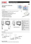
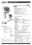
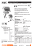
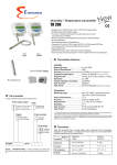
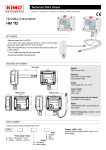
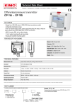
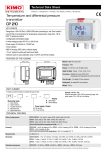
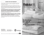
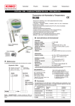
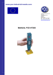
Humidity and temperature
transmitter
TH 210
KEY POINTS
- Configurable measuring ranges from 5 to 95%HR and from -40 to +180 °C (according the type
of probe)
- Functions : relative and absolute humidity, dew point, wet and dry temperature and enthalpy
- Stainless steel or polycarbonate probe
- 4 wires analogue output 0-5/10 V or 0/4-20 mA
- Power supply 24 Vdc/Vac or 115/230 Vac
- Trend indicator
- ABS V0 IP65 housing, with or without display
- “¼ turn” system mounting with wall-mount plate
FEATURES OF THE HOUSING
125 mm
59.2 mm
59.2 mm
Material : ABS V0 as per UL94
125 mm
Protection : IP65
100 mm
190 mm
115 mm
Display : 75 x 40 mm, LCD 20 digits 2 lines.
Remote model
Height of digits : Values : 10 mm ; Units : 5 mm
Cable gland : For cables Ø 8 mm maximum
Weight : 320 g
Ambient model
FUNCTIONS
TECHNICAL FEATURES IN HUMIDITY
Measuring range
From 5 to 95%RH
Unit of measurement
%RH
Accuracy* (Repeatability, linearity, hysteresis)
±1.5%RH (if 15°C ≤ T ≤ 25 °C)
Drift linked to temperature
±0.04 x (T-20)%RH (if T < 15°C or T > 25°C)
Resolution
0.1%RH
Factory calibration uncertainty
±0.88%RH
Response time
< 10 seconds (from 10 to 80%RH, Vair = 2 m/s)
Type of sensor
capacitive
Type of fluid
Air and neutral gases
Class 210 transmitters have two analogue outputs which
correspond to both displayed parameters. It is possible to
activate one or two outputs and to select for each
between humidity, temperature and the functions
described above** :
Absolute humidity : from 2 to 30 000 g/kg ; unit : 1 g/kg
Dew point : from -60 to +100 °Ctd ; unit : 0.1°Ctd / 0.1
°Ftd
Dry temperature : from -20 to +102 °C ; unit : 0.1°C /
0.1 °F
Enthalpy : from 0 to 15 000 Kj/kg ; unit : 0.1 Kj/kg
*All accuracies indicated in this technical datasheet were stated in laboratory conditions, and can be guaranteed for measurements carried out in the
same conditions, or carried out with calibration compensation.
As per NFX 15-113 and the Charter 2000/2001 HYGROMETERS, GAL (Guaranteed Accuracy Limit) which has been calculated with a coverage
factor value of 2 is ±2.58%RH between 18 and 28°C on the measuring range from 3 to 98%RH. Sensor drift is less than 1%RH/year.
**The default configuration for the output 1 is 0-100%RH in
hygrometry and 0-50°C in temperature for the output 2.
PART NUMBER
To order, just add the codes to complete the part number :
TH 210
Type of probe
Power supply / Output
B : 24 Vac/Vdc
H : 115 or 230 Vac
Display Mounting of the
probe
O : with display
N : without display
I : stainless steel
P : polycarbonate
Probe length (mm)
150 : remote
300 : remote
D : remote
S : ambient
Example : TH210 - BNDP150
Temperature and humidity transmitter, power supply 24 Vac/Vdc, without display, with remote probe in polycarbonate of 150 mm length.
TECHNICAL FEATURES IN TEMPERATURE
TECHNICAL SPECIFICATIONS
Measuring range
Ambient model : from 0 to +50 °C
Remote model with polycarbonate probe : from -20 to +80 °C
Remote model with stainless steel probe : from -40 to +180 °C
Power supply
24 Vac / Vdc ±10 %
115 Vac or 230 Vac ±10 %, 50-60 Hz
Unit of measurement
°C / °F
Accuracy*
±0.3 % of reading ±0.25 °C
Response time
T90 = 0.9 second for Vair = 1 m/s
Resolution
0.1 °C
Type of sensor
Pt100 1/3 as per DIN IEC751
Type of fluid
Air and neutral gases
Output
2 x 4-20 mA or 2 x 0-20 mA ou 2 x 0-5 V ou 2 x 010 V (4 wires)
Maximum load : 500 Ohms (0/4-20 mA)
Minimum load : 1 K Ohms (0-5/10 V)
Galvanic isolation
Inputs and outputs (models 115 Vac/230 Vac)
Outputs (models 24 Vac/Vdc)
*All the accuracies indicated in this technical datasheet were stated in laboratory conditions, and can be guaranteed for
measurements carried out in the same conditions, or carried out with calibration compensation.
Consumption
5 VA
TECHNICAL FEATURES OF THE PROBE
➢
Electromagnetical compatibility
EN61326
White polycarbonate probe
Measuring range
From -20 to +80 °C
Length of standard probe
100 mm
Length of remote probe
150 or 300 mm (other on request)
Cable
Silicone Ø4.8 mm, length 2 m (other on request)
Electrical connection
Screw terminal block for cable 2.5 mm²
PC communication
Kimo USB-Mini Din cable
Environment
Air and neutral gases
Polycarbonate probes are supplied with a flow-through polycarbonate protection tip with a
stainless steel filter 25 µ (ref. : EPP2).
➢
Type of fluid
Air and neutral gases
316 L stainless steel prone
Operating temperature
From 0 to +50 °C
Measuring range
From -40 to +180 °C
Length of remote probe
150 or 300 mm (other on request)
Cable
Silicone Ø4.8 mm, length 2 m (other on request)
Storage temperature
From -10 to +70 °C
Stainless steel probes are supplied with a flow through stainless steel protection tip
with a stainless steel filter 25 µ (ref. : EPI25).
➢
Type of tips
Part number
EPP2
EPI25
EPI100
EPFI
EPFT
EPH2O2
Tip material
PC(1)
St. steel(2)
St. steel(2)
St. steel(2) PTFE(3)
MnO2(4)
Filter material
St. steel
St. steel
St. steel
St. steel
PTFE
Filter type
Meshed
Meshed
Meshed
Sintered
Maximum particle
25 µ
25 µ
100 µ
10 µ
50 µ
50 µ
Maximum air velocity
25 m/s
25 m/s
20 m/s
30 m/s
25 m/s
25 m/s
Maximum temperature
120 °C
180 °C
120 °C
180 °C
180 °C
180 °C
Relative humidity maximum
95%RH
95%RH
100%RH
90%RH
90%RH
95%RH
Length
30 mm
30 mm
30 mm
30 mm
30 mm
33 mm
HVAC air-conditioning system
x
x
x
xx
x
x
Cold storage room
x
x
x
x
x
x
Industry
x
x
x
x
x
x
Pharma plants / Microelectronics
x
x
x
x
x
x
Dryer
x
x
x
x
x
x
Curing
x
x
x
x
x
x
Swimming-pool
x
x
x
x
x
x
Specifications
PTFE
Sintered Sintered
Application
External aggression :
Tips protect against the following external
aggressions :
●
Water droplets : EPFT
●
Shaving : EPI25 et EPFI
●
Dust : EPFI
●
Chemical product and grease :
EPFT
●
H2O2 (hydrogen peroxide) :
EPH2O2
(1)
PC : white polycarbonate
Stainless steel : 316 L
(3)
PTFE : white Teflon®
(4)
MnO2 : manganese dioxide
(2)
CONNECTIONS
Analogue outputs (a)
DIP switch
(d)
Type of power
supply of the
transmitter (b)
Power supply
terminal block
(c)
LCC-S software connections
(a)
Cable glands
Analogue output 1
(out 1)
Analogue output 2
(out 2)
(c)
(c)
or
GND – Ground
0/4-20 mA – Current
0-5/10 V – Voltage
GND – Ground
0/4-20 mA – Current
For power supply 230 Vac, 115
Vac models
For power supply 24
Vac models
For power supply 24
Vdc models
0-5/10 V – Voltage
(c)
or
Ground
Neutral (N)~
Phase (L)~
Neutral (N)~
Phase (L)~
+
ELECTRICAL CONNECTIONS – as per NFC15-100 standard
This connection must be made by a qualified technician. To make the connection, the transmitter must not be energized.
Before making the connection, you must first check the power supply indicated on the transmitter board (see (b) on “Connections” part).
➢
Power supply
24 Vdc
➢
The selection of the output signal in voltage (0-10 V or 0-5 V) or in current (4-20 mA
or 0-20 mA) is made via the DIP switch (d) of the electronic board of the transmitter :
put the on-of switches as shown in the table below :
For transmitters with 24 Vdc power supply :
-
-
+
+
Configurations
~
~ Vac N~
Vac L~
230 Vac
➢
N
L
0-5 V
0-20 mA
1 2 3 4
1 2 3 4
1 2 3 4
1 2 3 4
Connection of the output
in current 4-20 mA :
0/4-20 mA
-
+
➢
Connection of output in
voltage 0-10 V :
0-5/10 V
+
-
0/4-20 mA
N
L
For transmitters with 115 or 230 Vac power
supply :
A
Ground
Power supply
115 / 230 Vac
➢
0-5/10 V
or
Pe
N
L
Power supply
0-10 V
Combinations
For transmitters with 24 Vac power supply :
Power supply 24 Vac
class II
~
Pe
N
230 Vac
L
~
4-20 mA
Neutral
Phase
Regulator display or
PLC/BMS passive
type
4-20 mA output
V
Regulator display or
PLC/BMS passive
type
0-10 V output
CONFIGURATION OF THE TRANSMITTERS
It is possible on the class 210 to configure all the parameters of the transmitter : units, measuring ranges, outputs, channels, calculation
functions, etc, via different methods :
●
Keypad for models with display : a code-locking system allows to secure the installation (See class 210 user manual).
●
Software (optional) on all models. Simple user-friendly configuration. See LCC-SD user manual.
Configurable analogue output :
Range with center zero (-40/0/+40 °C), with offset zero (-30/0/+70 °C) or standard range (0/+100 °C), It is possible to configure your own
intermediary ranges
Caution : the minimum difference between the high range and the low range is 20.
Configure the range according to your needs : outputs are automatically adjusted to the new measuring range
0
+180 °C
-40 °C
0
+180°C
50
New range
0V
4 mA
10 V
20 mA
0V
4 mA
10 V
20 mA
75 mm
MOUNTING
37.5 mm
23.75 mm
40 mm
4.5 mm
14 mm
7.5 mm
CALIBRATION
Outputs diagnostic : With this function, you can check with a multimeter (or on a regulator / display, or a PLC / BMS) if the transmitter outputs
work properly. The transmitter generates a voltage of 0 V, 5 V and 10 V or a current of 4 mA, 12 mA and 20 mA
Certificate : Class 210 transmitters are supplied with adjusting certificates. Calibration certificates are available as an option.
MAINTENANCE
Please avoid any aggressive solvent. Please protect the transmitter and its probes from any cleaning product containing formalin, that may be
used for cleaning rooms or ducts.
OPTIONS AND ACCESSORIES
●
●
LCC-S : configuration software with USB cable
Calibration certificate
●
●
●
Sliding fittings
Connection fittings
Cable glands
●
●
Protections tips
Wall-mounting support
bracket for remote humidity
probe
68 mm
8 mm
50 mm
To mount the transmitter, mount the ABS plate on the wall (drilling : Ø6 mm, screws and
pins are supplied).
Insert the transmitter on the fixing plate (see A on the drawing beside). Rotate the
housing in clockwise direction until you hear a “click” which confirms that the transmitter
is correctly installed.
FTang – transmitter_TH210 – 02/04/13 – RCS (24) Périgueux 349 282 095 Non-contractual document – We reserve the right to modify the characteristics of our products without prior notice.
-40 °C