1
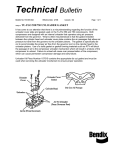
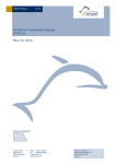
APPLICATION NOTE 203
STM 110 BATTERY POWERED –
Power Supply Alternative to Solar Cell
Applications based on STM 100/110 without enough Illumination
Alternatively to the use of a standard solar panel, e.g. in applications with no or not enough
light, the power supply standard input V_SC1 of the STM 110/110C module can be driven
by another suitable external energy sources of 2.2 - 5.0 V like a small Li/MnO2 coin cell for
example.
In sleep mode the supply current of the STM 110 module (V_SC1) is typically around 100
nA only. In operation the module current consumption strongly depends on the frequency
of measurements and radio transmissions. Please notice that the V_SC1 power supply is
buffered by an internal on-module capacitor, so the average current over time has to be
considered for calculation of the module current consumption.
Estimation of the Module Average Current Consumption
Using the following tables from chapter 2.4 of the STM 110 User Manual the supply current
of the module can be calculated in dependence of measurements on average (= Wakeup cycle time in „s“ seconds) and transmissions on average (= sending a telegram every
„m“ measurement cycles):
Fig. 1: Equivalent schematic of V_SC1 input
© EnOcean | www.enocean.com
Subject to modifications | Armin Anders | January 2009 | Page 1/ 2
APPLICATION NOTE 203
STM 110 BATTERY POWERED
Typical Calculation Examples
a) Cyclic measurement every 10 s, Transmission every 15 minutes on daily average
I_STM ≈ 4.0 μA (transmission every 100th wake up on average)
b) Cyclic wake up disabled, WAKE inputs operated around 10 times a day
I_STM ≈ 0.35 μA (transmission every 110 s x 100)
Lithium Batteries
For low cost applications standard manganese dioxide lithium 3 V coin battery can be used.
Depending on the energy demand different capacity sizes can be chosen. Please note that
most of the small coin batteries are not dimensioned for the required (short) current peaks
of up to 30 mA. Both V_SC power inputs of the STM 110/110C do have internal block capacitors, so additional external capacitors are not needed. With the upper mentioned scenario a) and a battery capacity of > 0.220 Ah (e.g. type CR2032), the lifetime is > 3 years
(0.220 Ah/2/4 μA). This calculation considers a margin of 50% from the nominal capacity
as available in praxis.
Using the integrated Goldcap for stronger power buffering
Generally it is not recommended to use the V_SC2 while using battery because the internal
Goldcap draws an inherent additional leakage current. However if a stronger power buffering is desired, that can be easy realized by simply connecting the V_SC2 input in parallel to
V_SC1. For more details please consult the user manual.
Fig. 1: Equivalent schematic of V_SC2 input
Power Supply Monitor
In general please consider the limited life time behavior of batteries, even if the energy
balance calculation indicates a multiple year operation time. It also could be useful to have
a control of the supply voltage to know in time when the battery voltage fails below a certain limit to be changed before failure. The circuitry described in the Application Note
“AN309 POWER SUPPLY MONITOR” can be used to do this.
Disclaimer
The information provided in this document describes typical features of the EnOcean radio system and should not
be misunderstood as specified operating characteristics. No liability is assumed for errors and / or omissions. We
reserve the right to make changes without prior notice. For the latest documentation visit the EnOcean website at
www.enocean.com.
© EnOcean | www.enocean.com
Subject to modifications | Armin Anders | January 2009 | Page 2/ 3