1
Repeater User Manual
working frequency only.
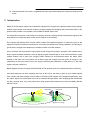
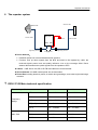
The uplink signal of mobile terminal from the coverage area is input via the server antenna, then filtered
by duplexers and FC unit, amplified by the uplink low noise amplifier (LNA) and the uplink PA unit and finally
sent via the donor antenna to the BTS.
Modules in the system diagram:
l Combiner:The main purpose of combiner is to combine quint system to share the same
antennas.
l Duplexer: The main purpose of duplexer is to combine downlink and uplink to share the same
antennas, the duplexer is composted of one pair of band pass filter that can not only reject the
spurious interference, but also increase the isolation of Uplink and Downlink.
l LNA: LNA is the first active sub system of the repeater, of which low noise and high linearity is
requested under strong input signals. LNA is the major sub system that determines the noise
figure of the repeater system.
l FPGA: Field-Programmable Gate Array, to process the digital signal transferred from analog
signal.
l PA: The power amplifier sub system helps the repeater to reach its targeted output power,
linearity of which decides the linearity of the repeater.
l Power supply is to supply power electricity to all repeaters’ modules.
-6-