1
SI-APPMOD-HourMeter
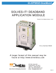
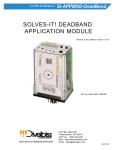
SOLVES-IT! HOUR METER
APPLICATION MODULE
Revision 0 for Software Version 1.0.0.0
PLC on a Chip Patent 7,299,099
A larger format of this manual may be
found at http://www.divelbiss.com
Smart Parts for Managing Automation
9778 Mt. Gilead Rd.
Fredericktown, OH 43019
Toll Free: 1-800-245-2327
Web: http://www.divelbiss.com
Email: [email protected]
2008014.0
Table of Contents
TABLE OF CONTENTS
Table of Contents
Package Contents
Page 1
Page 1
Getting Started
How to Use this Manual
Page 2
Page 2
SI-APPMOD-HourMeter Basics
Get to Know the Module
Module Mounting
Module Input Power
Module Operation
User Interface
Input Connections
Output Connections
Changing Setpoints
Expandability / Customization
Programmed from Factory Specifications
Page
Page
Page
Page
Page
Page
Page
Page
Page
Page
Page
3
3
4
4
5
5
6
6
7
8
8
WARNING!
The SI-APPMOD-HOURMETER, as with programmable controllers, must not be used alone in applications which would be
hazardous to personnel in the event of failure of this device.
Precautions must be taken by the user to provide mechanical
and/or electrical safeguards external to this device. This device
is NOT APPROVED for domestic or human medical use.
PACKAGE CONTENTS
Whats Included
Qty
1
1
1
4
Description
Part Number
Location
SI-200 with Software Pre-loaded
SI-APPMOD-HOURMETER Manual
Din-rail Socket
Commutating Diodes
SI-200
2008014.X
115-105328
111-101012
In
In
In
In
SI-APPMOD-HourMeter User Manual
Document #: 2008014.0.pdf
Box
Box
Box
Box
Page 1 of 8
Divelbiss Corporation 9778 Mt. Gilead Rd. Fredericktown, Ohio 43019 1-800-245-2327 www.divelbiss.com
GETTING STARTED
This section explains how to read this manual and understand the symbols.
HOW TO USE THIS MANUAL
In this manual, the following conventions are used to distinguish elements of text:
BOLD
Denotes labeling, commands, and literal portions of
syntax that must appear exactly as shown.
italic
Used for variables and placeholders that represent the type of text
to be entered by the user.
SMALL CAPS
Used to show key sequences or actual buttons, such as
the OK button.
OK,
where the user clicks
In addition, the following symbols appear periodically in the left margin to call the readers attention to specific details in
the text:
Warns the reader of a potential danger or hazard that is associated
with certain actions.
Appears when the text contains a tip that is especially helpful.
Indicates that the text contains information to which the reader
should pay particularly close attention.
All Information and Specifications Subject to Change without Notice
SI-APPMOD-HourMeter User Manual
Document #: 2008014.0.pdf
Page 2 of 8
Divelbiss Corporation 9778 Mt. Gilead Rd. Fredericktown, Ohio 43019 1-800-245-2327 www.divelbiss.com
MODULE BASICS
This section describes the SI-APPMOD-HourMeter Application Module including input/output assignments and an operational description.
GETTING TO KNOW THE MODULE
The module is connected to external devices via its included mounting socket.
Connector Pin out
Bottom View (Solves-It! Connector)
Pin
Pin
Pin
Pin
Pin
Pin
Pin
Pin
Pin
Pin
Pin
1
2
3
4
5
6
7
8
9
10
11
Setpoint 2 Output
Setpoint 1 Output
Hour Meter Reset Input
Hour Meter Overflow Alarm Reset Input
Input 2 - Not Used
Input 3 - Not Used
Earth Gnd
Input Power Common
10-24.5VDC Input Power
Output 4 - Not Used
Output 3 - Not Used
Figure 2.1 - Module Pin-Out
SI-APPMOD-HourMeter User Manual
Document #: 2008014.0.pdf
Page 3 of 8
Divelbiss Corporation 9778 Mt. Gilead Rd. Fredericktown, Ohio 43019 1-800-245-2327 www.divelbiss.com
Module Basics
MODULE MOUNTING
The Module mounts to an industry standard 11-pin Octal relay socket. To mount the module, align with the socket and
firmly push into position.
MODULE INPUT POWER
The module can be powered with 10-24.5VDC. The input power must be of sufficient supply to drive the module and the
outputs (based on the load currents for each) Maximum current for the module is 150mADC and maximum load for
each outputs is 300mADC. For the pre-programmed software, 2 outputs are used and may be on at a time. Exceeding a
total output load of greater than 1ADC (more than 3 outputs at full load simultaneously) can damage the module.
+10-24.5VDC
POWER IN
11
10
9
7
8
EARTH
GND
-DC /
POWER
COMMON
Status
I1
Programming
Port
I2
I3
I4
Setpoint / Variable Display
APPLICATION MODULE
INPUT POWER
Shown installed in provided
mounting socket
B1
1
B2
2
SI-200
3
4
5
6
Figure 2.2 - Module Input Power Diagram
SI-APPMOD-HourMeter User Manual
Document #: 2008014.0.pdf
Page 4 of 8
Divelbiss Corporation 9778 Mt. Gilead Rd. Fredericktown, Ohio 43019 1-800-245-2327 www.divelbiss.com
Module Basics
MODULE OPERATION
The SI-APPMOD-HourMeter operates an an on-power timer. For each second the module is powered, the hour meter
will increment. While only hours are displayed, the module keeps time to a one-second resolution. Two individual setpoints and outputs are provided as alarm features. Each setpoint can be set from 0 to 9999 hours. When the hourmeter
time reaches each setpoint, its output will energize.
The hourmeter will operate up to 9999 hours before overflowing and wrapping back to zero. If this should occur, I4 will
flash indicating the hour meter has rolled over to zero. Two reset inputs are provided. One resets the actual hour meter
to zero and the other resets the Overflow Alarm.
USER INTERFACE
The user interface consists of two push-buttons; labeled B1 and B2, the Setpoint/Variable Display, four LED indicators
(I1-I4) and the Status LED indicator.
1. Indicator 1
On-Steady indicates that elapsed time is displayed
on the Setpoint / Variable Display.
5
1
4
3
2
2. Indicator 2
On-Steady indicates that the Alarm/Setpoint 1 time is displayed
on the Setpoint / Variable Display.
3. Indicator 3
On-Steady indicates that the Alarm/Setpoint 2 time is displayed
on the Setpoint / Variable Display.
Status
4. Indicator 4
I1
I2
I3
Setpoint / Variable Display
Programming
Port
I4
Flashing indicates the hour meter has rolled over (> 9999)
and has reset to zero.
5. Module Status Indicator
Flashing slowly indicates module problem
Flashing quickly indicated module is operating .
6. B1 Push-button
Each press will cycle one-step through the module menu.
B2
B1
SI-200
1. Actual Elapsed Hours
2. Alarm/Setpoint 1
3. Alarm/Setpoint 2
7. B2 Push-button
6
7
8
For each Setpoint displayed, pressing the B1 will increment
the displayed setpoint by one (1). Holding the B2 button will cause the
setpoint to increment by 10's then 100's then 1000's.
8. Setpoint / Variable Display
View the current elapsed time, configure the setpoints.
Figure 2.3 - User Interface
SI-APPMOD-HourMeter User Manual
Document #: 2008014.0.pdf
Page 5 of 8
Divelbiss Corporation 9778 Mt. Gilead Rd. Fredericktown, Ohio 43019 1-800-245-2327 www.divelbiss.com
Module Basics
INPUT CONNECTIONS
Two inputs are pre-programmed and must be wired to take advantage of functionality. Input 1 is used to reset the hour
meter elapsed time. If this input is energized, the hour meter will reset immediately. Input 2 is used to reset the
Overflow/Rollover Alarm. Figure 2.4 provides a sample connection. As shown in Figure 2.4, switches are used to illustrate what is required; although, any device that operates the same may be used.
11
10
9
8
7
-DC /
POWER
COMMON
Status
I1
Programming
Port
1
2
I3
I4
Setpoint / Variable Display
SI-200
B2
B1
I2
3
4
5
6
RESET HOUR METER
RESET OVERFLOW ALARM
Figure 2.4 - Enable Input Connections
OUTPUT CONNECTIONS
When outputs are energized, the output pin will be sourced with +V (equal to the module input power voltage). Each
output can drive a load up to 300mA maximum (resistive). Depending upon the device connected to an output, a minimum load resistor may be required. If the output is energized at all times, connect a 470Ω to 1KΩ load from the output
to common. Figure 2.5 is a typical output wiring diagram.
The factory installed software for this module will only allow two outputs to be energized at a time. Max total current for
simultaneous outputs is 1ADC. Simultaneous output loads greater than 1A may result in damage to the module. Care
must be taken to ensure the loads connected to the outputs if all channels are used does not exceed 1A.
SI-APPMOD-HourMeter User Manual
Document #: 2008014.0.pdf
Page 6 of 8
Divelbiss Corporation 9778 Mt. Gilead Rd. Fredericktown, Ohio 43019 1-800-245-2327 www.divelbiss.com
Module Basics
+10-24.5VDC
11
ALARM / SETPOINT 2
LOAD / DEVICE
10
9
8
7
EARTH
GND
-DC /
POWER
COMMON
Status
I1
I2
I3
I4
ALARM / SETPOINT 1
Programming
Port
LOAD / DEVICE
Output Voltage will be
equal to Input Voltage
on Pin 9
B1
1
Setpoint / Variable Display
B2
2
SI-200
3
4
5
6
Figure 2.5 - Typical Output Connections
CHANGING SETPOINTS
Indicators I1-I3 represent in order: Current Elapsed Time (in hours), Alarm/Setpoint 1(in hours), Alarm/Setpoint 2 (in
hours). Pressing the B1 button repeatedly will cycle through and display these items.
CHANGING THE SETPOINT
1. Using the B1 button, cycle through the menu until the alarm/setpoint is displayed (indicated by the I1-I3 indicators).
2. Press the B2 button repeately to increment the setpoint time in 1 hour increments. Pressing and holding the B2
button will cause the increment to increase to 10’s, 100’s then 1000’s. The count will increase to 9999 counts then
reset and begin from zero.
To exit from the setpoint, press the B1 button to the next menu item.
SI-APPMOD-HourMeter User Manual
Document #: 2008014.0.pdf
Page 7 of 8
Divelbiss Corporation 9778 Mt. Gilead Rd. Fredericktown, Ohio 43019 1-800-245-2327 www.divelbiss.com
Module Basics
EXPANDABILITY / CUSTOMIZATION
As the module is based on the Solves-It!, Model SI-200, the program can be customized and its functionality expanded.
Accessories are required. The program that was factory installed can be downloaded from
http://www.divelbiss.com. The program can be edited to add additional functionality and logic. To gain functionality of
some inputs and/or outputs, it may be necessary to re-assign the I/O that was factory configured. For more information
about changing the functionality, download the Solves-It! User Manual and the EZ LADDER User Manual.
The following accessories are required to re-program the module and are included in the SI-APPMOD-PGMKIT:
1. SI-PGM
2. EZLDCD-02
Solves-It! Programming Cable
EZ LADDER Lite on CD.
PROGRAMMED FROM FACTORY SPECIFICATIONS
Processor:
Solves-It! Model 200, Based on PLC on a ChipTM
Memory:
64K Flash
Outputs:
2 Sourcing SSR Outputs, rated 10-24VDC @ 300mADC Max. each. Max total output load =
1ADC @ 24VDC power input. Output Voltage = Input Power
Functionality: Alarm/Setpoints 1 & 2
Power Requirements:
Indicators:
Digital Inputs:
10-24.5VDC @ 150mADC Max
I1-I4 LED Indicator, 1 Status LED Indicator
2 Sourcing Inputs
Hourmeter Reset / Hourmeter Overflow Alarm Reset
Display:
Push Buttons:
Operating Temp:
Dimensions:
Mounting:
Type:
4 Digit, 7 Segment Programmable LED Display
2 Programmable Push Buttons
0-60º C
3.62” Wide x 5.21” Length x 1.21” Tall.
Plugs into Industry standard 11-pin Octal Relay Socket
Plastic Housing
SI-APPMOD-HourMeter User Manual
Document #: 2008014.0.pdf
Page 8 of 8
Divelbiss Corporation 9778 Mt. Gilead Rd. Fredericktown, Ohio 43019 1-800-245-2327 www.divelbiss.com
Limited Warranty
Divelbiss Corporation warrants equipment will be free from defects in material and workmanship for
a period of one (1) year from the date of the Divelbiss invoice that the equipment was furnished.
Divelbiss Corporation will not be liable for any design furnished by Buyer and incorporated into the
equipment.
In no event shall Divelbiss Corporation be liable for anticipated profits, consequential damages or
loss of use of equipment or of any installation into which the equipment covered by this order may
be put.
Divelbiss Corporation shall not be liable or responsible for any loss, injury, or damage resulting
directly or indirectly from the use of software and/or programming in any way associated with the
equipment of this order.
Obligations are to be limited to the repair or replacement at the Divelbiss Corporation plant,
Fredericktown, Ohio, upon return of the part or component in question, prepaid by Buyer. The return
freight charges to be paid by Divelbiss. The part or component is only to be returned to Divelbiss
with a Returned Material Authorization number issued by the Divelbiss Service Department. Any
warranty service (consisting of time, travel, and expenses related to such services) performed other
than at Divelbiss Corporation plant, shall be at Buyer's expense.
Warranty of repaired or replacment products will be limited to ninety (90) days or the remainder of
the original warranty whichever is greater.
Warranty is available only if Divelbiss Corporation is promptly notified in writing upon discovery of
any alleged defect and examination of the subject product discloses, to Divelbiss satisfaction, that
any defect has not been caused by misuse; neglect; improper installation; improper operation;
improper maintenance, repair, or alteration; accidents; or unusual deterioration or degradation of the
equipment or parts thereof due to physical environment or due to electrical or electromagnetic noise
environment.
This warranty is in lieu of all other warranties, expressed, implied, or statutory, including warranties
of merchantability or fitness for a specific purpose.