1
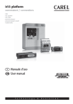
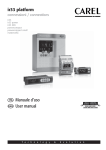
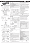
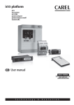
ir33 platform
connessioni / connections
ir33
ir33 power
ir33 DIN
powercompact
powercompact small
mastercella
Manuale d’uso
User manual
User manual
ENGLISH
We wish to save you time and money!
We can assure you that the thorough reading
of this manual will guarantee correct installation and safe use of the product described.
IMPORTANT WARNINGS
CAREL bases the development of its products on decades of experience in HVAC, on the continuous
investments in technological innovations to products, procedures and strict quality processes with incircuit and functional testing on 100% of its products, and on the most innovative production technology
available on the market.
CAREL and its subsidiaries nonetheless cannot guarantee that all the aspects of the product and the software included with the product respond to the requirements of the final application, despite the product
being developed according to start-of-the-art techniques. The customer (manufacturer, developer or
installer of the final equipment) accepts all liability and risk relating to the configuration of the product
in order to reach the expected results in relation to the specific final installation and/or equipment.
CAREL may, based on specific agreements, acts as a consultant for the positive commissioning of the
final unit/application, however in no case does it accept liability for the correct operation of the final
equipment/system.
The CAREL product is a state-of-the-art product, whose operation is specified in the technical documentation supplied with the product or can be downloaded, even prior to purchase, from the website www.
carel.com.
Each CAREL product, in relation to its advanced level of technology, requires setup/configuration/programming/commissioning to be able to operate in the best possible way for the specific application. The
failure to complete such operations, which are required/indicated in the user manual, may cause the
final product to malfunction; CAREL accepts no liability in such cases.
Only qualified personnel may install or carry out technical service on the product.
The customer must only use the product in the manner described in the documentation relating to the
product.
In addition to observing any further warnings described in this manual, the following warnings must be
heeded for all CAREL products:
• Prevent the electronic circuits from getting wet. Rain, humidity and all types of liquids or condensate
contain corrosive minerals that may damage the electronic circuits. In any case, the product should be
used or stored in environments that comply with the temperature and humidity limits specified in the
manual.
• Do not install the device in particularly hot environments. Too high temperatures may reduce the life
of electronic devices, damage them and deform or melt the plastic parts. In any case, the product
should be used or stored in environments that comply with the temperature and humidity limits
specified in the manual.
• Do not attempt to open the device in any way other than described in the manual.
• Do not drop, hit or shake the device, as the internal circuits and mechanisms may be irreparably
damaged.
• Do not use corrosive chemicals, solvents or aggressive detergents to clean the device.
• Do not use the product for applications other than those specified in the technical manual.
All of the above suggestions likewise apply to the controllers, serial boards, programming keys or any
other accessory in the CAREL product portfolio.
CAREL adopts a policy of continual development. Consequently, CAREL reserves the right to make
changes and improvements to any product described in this document without prior warning.
The technical specifications shown in the manual may be changed without prior warning.
The liability of CAREL in relation to its products is specified in the CAREL general contract conditions,
available on the website www.carel.com and/or by specific agreements with customers; specifically, to
the extent where allowed by applicable legislation, in no case will CAREL, its employees or subsidiaries
be liable for any lost earnings or sales, losses of data and information, costs of replacement goods or
services, damage to things or people, downtime or any direct, indirect, incidental, actual, punitive, exemplary, special or consequential damage of any kind whatsoever, whether contractual, extra-contractual
or due to negligence, or any other liabilities deriving from the installation, use or impossibility to use the
product, even if CAREL or its subsidiaries are warned of the possibility of such damage.
Disposing of the parts of the controller:
The controller is made up of metal and plastic parts and a lithium battery. All these parts
must be disposed of separately in compliance with the local standards in force on waste
disposal.
4
ir33 platform “connections” +030220445 - rel. 2.0 - 01.05.2006
1. POWERCOMPACT
ENGLISH
Contents
7
1.1 Dimensions ............................................................................................................................................7
1.2 Electrical specifications ........................................................................................................................7
1.3 Electrical connections ..........................................................................................................................9
2. POWERCOMPACT SMALL
10
2.1 Dimensions............................................................................................................................................10
2.2 Electrical specifications........................................................................................................................10
1.3 Electrical connections ..........................................................................................................................12
3. MASTERCELLA 2
13
3.1 Dimensions............................................................................................................................................13
3.2 Technical specifications .......................................................................................................................13
3.3 Electrical connections ..........................................................................................................................14
4. IR33
15
4.1 Dimensions............................................................................................................................................15
4.2 Electrical specifications........................................................................................................................15
4.3 Electrical connections ..........................................................................................................................17
5. IR33POWER
19
5.1 Dimensions............................................................................................................................................19
5.2 Electrical specifications........................................................................................................................19
5.3 Electrical connections ..........................................................................................................................21
6. IR33DIN
22
6.1 Dimensions............................................................................................................................................22
6.2 Electrical specifications........................................................................................................................22
6.3 Electrical connections ..........................................................................................................................24
ir33 platform “connections” +030220445 - rel. 2.0 - 01.05.2006
5
1.1 Dimensions
Appearance and ergonomics:
The appearance has been designed to fit in harmoniously with the new lines of the refrigeration units.
The main characteristic is its compactness: the dimensions are in fact 167x 36 x75 mm in the standard version.
Key:
1. drilling template 138.5 x 29 mm;
2. faston (spade) version + 8 mm
Fig. 1.a
1.2 Electrical specifications
Power supply
model E:
model A:
model H:
model 0:
Insulation guaranteed by the power
supply
Inputs
Type of probe
voltage
230 V~ 50/60 Hz;
230 V~ 50/60 Hz, 16 A, 8 A, 8 A version;
115 V~ 50/60 Hz;
115 V~ 50/60 Hz, 16 A, 8 A, 8 A version;
115-230 Vac 50/60Hz
12 V~ , 50/60Hz
12 Vdc, 12-18Vdc
power
3 VA, 25 mA~ max
3 VA, 25 mA~ max
3 VA, 50 mA~ max
3 VA, 50 mA~ max
6 VA, 50mA~ max
4 VA, 300 mA~ max
TRADR4W012 transformer, 315 mA slow-blow fuse in secondary,
only use SELV power supply
power
reinforced.; 6 mm air, 8 mm surface; 3750 V insulation
basic; 3 mm air, 4 mm surface; 1250 V insulation
to be guaranteed externally by safety transformer
basic; 3 mm air, 4 mm surface; 1250 V insulation
voltage
insulation from very low voltage parts
insulation from relay outputs
model 0:
insulation from very low voltage parts
insulation from relay outputs
S1
NTC or PTC, depending on the model
S2
NTC or PTC, depending on the model
DI1
voltage-free contact, contact resistance < 10 ohm, closing current 6 mA
S3
NTC or PTC, depending on the model
DI2
voltage-free contact, contact resistance < 10 ohm, closing current 6 mA
S4
NTC or PTC, depending on the model
Maximum distance between probes and digital inputs less than 10 m
Note: in the installation, keep the power supply and load connections separate from the probe, digital inputs, repeater display and supervisor
cables.
Std. Carel NTC
10 kΩ at 25 °C, range –50T90 °C
measurement error: 1 °C in the range –50T50 °C
3 °C in the range +50T90 °C
High temperature NTC
50 kΩ at 25 °C, range –40T150 °C
measurement error: 1.5 °C in the range –20T115 °C
4 °C in the range outside of -20T115 °C
Std. Carel PTC (specific model)
985 Ω at 25°C, range -50T150 °C
measurement error: 2 °C in the range –50T50 °C
4 °C in the range +50T150 °C
model E, A, H:
ir33 platform “connections” +030220445 - rel. 2.0 - 01.05.2006
7
ENGLISH
1. POWERCOMPACT
ENGLISH
Relay outputs
Connections
Case
Assembly
Wide vers. case
(power supply E, A, H, O)
Assembly
(power supply E, A, H, O)
Wide versions
Display
Keypad
Infrared receiver
Clock with backup battery
Buzzer
Clock
Operating conditions
Storage conditions
Front panel index of protection
Environmental pollution
PTI of insulating materials
Period of stress across the insulating parts
Category of resistance to fire
Class of protection against voltage surges
Type of action and disconnection
Construction of the control device
Classification according to protection
against electric shock
Device designed to he hand-held or
integrated into equipment designed to
be hand-held
Software class and structure
Cleaning the front panel of the instrument
Serial interface for CAREL network
Interface for repeater display
Maximum distance between interface
and display
Programming key
depending on the model
5A
EN60730-1: 250 V~ 5 (1) A;
100,000 operating cycles
UL 873:
250 V~ 5A res 1FLA 6LRA C300;
30,000 operating cycles
8A
EN60730-1: 250 V~ 8 (4) on N.O., 6 (4) on N.C., 2 (2) on N.O. and N.C.; 100,000 operating cycles
UL 873:
250 V~ 8A res 2FLA 12LRA C300;
30,000 operating cycles
16 A
EN60730-1: 250 V~ 10 (4) A up to 60°C on N.O., 12 (2) A on N.O. and N.C.;100,000 operating cycles
UL 873:
250 V~ 12A res 5FLA 30LRA C300;
30,000 operating cycles
2HP
EN60730-1: 250 V~ 10 (10) A;
100,000 operating cycles
UL 873:
250 V~ 12A res 12FLA 72LRA;
30,000 operating cycles
insulation from very low voltage parts
reinforced; 6 mm air, 8 mm surface; 3750 V insulation
insulation between the relay outputs
basic; 3 mm air, 4 mm surface; 1250 V insulation
Type of connection
Cross-sections
Maximum current
fixed screw
for cables from 0.5 to 2.5 mm²
12A
plug-in for screw blocks
spade with crimped contact
The correct sizing of the power and connection cables between the instrument and the loads is the responsibility of the installer.
In the max load and max operating temp. conditions, the cables used must be suitable for operation up to 105°C.
plastic: dimensions 36x167x75 mm; mounting depth 64 mm
smooth, hard and indeformable panel: using screws from the front
drilling template: dimensions 29x138.5 mm; distance between fastening screws 153.5mm
fastening screws: countersunk head with maximum thread diameter 3.9mm
plastic
dimensions: 39.4x183x75
mounting depth 63 mm
smooth, hard and indeformable panel
using screws from the front or brackets
drilling template
dimensions: from 138.5x29 to 150x31
distance between fastening screws: 165 mm or 153.5
digits: 3 digit LED
display: from -99 to 999
operating status: indicated with graphic icons on the display
8 silicone rubber buttons
available depending on the model
available depending on the model
available in all models
Error at 25 °C:
± 10 ppm (±5.3 min/year)
Error in the temperature range -10T60 °C:
- 50ppm (-27min/year)
Ageing:
< ±5p pm (±2.7 min/year)
Discharge time:
typically 6 months (8 months maximum)
Recharge time:
typically 5 hours (< 8 hours maximum)
-10T65 °C; <90% RH non-condensing
-20T70 °C; <90% RH non-condensing
assembly on smooth and indeformable panel with IP65 gasket
2, normal situation
printed circuits 250, plastic and insulating materials 175
long
category D and category B (UL 94-V0)
category II
1B relay contacts (micro-disconnection)
electronic control device incorporated
class II when appropriately integrated
no
class A
only use neutral detergents and water
External, available in all models
External, available in models with H and 0 power supplies
10 m
Available in all models
fastening screws
countersunk head with maximum thread diameter 3.9 mm for 165 mm spacing
flat head for 153 mm spacing, maximum thread diameter 3 mm
Table 1.a
8
ir33 platform “connections” +030220445 - rel. 2.0 - 01.05.2006
ENGLISH
1.3 Electrical connections
PB00C
PB00F0E
PB00F0H
PB00H
PB00S
PB00Y
NETWORK
Fig. 2.b
ir33 platform “connections” +030220445 - rel. 2.0 - 01.05.2006
9
2.1 Dimensions
28.2
39.4
Appearance and ergonomics:
The appearance has been designed to fit in harmoniously with the new lines of the refrigeration units.
The main characteristic is its compactness: the dimensions are 167 x 36 x 51 mm.
AUX
40
183.4
45
dima di foratura
drilling template
da 138.5 a 150 x 31mm
36
ENGLISH
2. POWERCOMPACT SMALL
167
153.5
165
Key:
1. drilling template 138.5 x 29 mm.
Fig. 2.a
2.2 Electrical specifications
voltage
power
Power supply
model S:
115 - 230 V~ 50/60 Hz;
6 VA, 50 mA~ max
Insulation guaranteed by the power supply insulation from very low voltage parts
reinforced; 6 mm air, 8 mm surface; 3750 V insulation
insulation from relay outputs
basic; 3 mm air, 4 mm surface; 1250 V insulation
Inputs
S1
NTC or PTC, depending on the model
S2
NTC or PTC, depending on the model
DI1
voltage-free contact, contact resistance < 10 ohm, closing current 6 mA
S3
NTC or PTC, depending on the model
DI2
voltage-free contact, contact resistance < 10 ohm, closing current 6 mA
S4
NTC or PTC, depending on the model
Maximum distance between probes and digital inputs less than 10 m. Note: in the installation, keep the power supply and load connections
separate from the probe, digital inputs, repeater display and supervisor cables.
Type of probe
Std. Carel NTC
10 kΩ at 25 °C, range –50 to 90 °C
measurement error: 1 °C in the range –50 to 50 °C
3 °C in the range +50 to 90 °C
High temperature NTC
50 kΩ at 25 °C, range –40 to 150 °C
measurement error: 1.5 °C in the range –20 to 115 °C
4 °C in the range outside of -20 to 115 °C
Std. Carel PTC (specific model)
985 Ω at 25°C, range -50 to 150 °C
measurement error: 2 °C in the range –50 to 50 °C
4 °C in the range +50 to 150 °C
Relay outputs
depending on the model
5A
EN60730-1: 250 V~ 5 (1) A;
100,000 operating cycles
UL 873:
250 V~ 5A res 1FLA 6LRA C300;
30,000 operating cycles
8A
EN60730-1: 250 V~ 8 (4) on N.O., 6 (4) on N.C., 2 (2) on N.O. and N.C.; 100,000 operating cycles
UL 873:
250 V~ 8A res 2FLA 12LRA C300;
30,000 operating cycles
30 A
EN60730-1: 250 V~ 12 (10) A;
100,000 operating cycles
UL 873:
250 V~ 12A res 2HP 72LRA;
30,000 operating cycles
insulation from very low voltage parts
reinforced; 6 mm air, 8 mm surface; 3750 V insulation
insulation between the relay outputs
basic; 3 mm air, 4 mm surface; 1250 V insulation
Connections
Type of connection
Cross-sections
Maximum current
fixed screw
for cables from 0.5 to 2.5 mm2
12A
plug-in for screw blocks
fixed screw vertical
spade with crimped contact
The correct sizing of the power and connection cables between the instrument and the loads is the responsibility of the installer.
Maximum current at terminals 4 and 7 is 12A. In the max load and max operating temp. conditions, the cables used must be suitable for operation up to 105°C.
10
ir33 platform “connections” +030220445 - rel. 2.0 - 01.05.2006
plastic: dimensions 36x167x45 mm; mounting depth 40 mm
smooth, hard and indeformable panel: using screws from the front
drilling template: dimensions 29x138.5 mm; distance between fastening screws 153.5 mm
fastening screws: countersunk head with maximum thread diameter 3.9 mm
Wide vers. case
plastic
dimensions: 39.4x183x45
(power supply S)
mounting depth 40 mm
Assembly
smooth, hard and indeformable panel
using screws from the front or brackets
(power supply S)
drilling template
dimensions: from 138.5x29 to150x31
Wide versions
distance between fastening screws: 165 mm or 153.5
fastening screws
countersunk head with maximum thread diameter 3.9 mm for 165 mm spacing
flat head for 153 mm spacing, maximum thread diameter 3 mm
Display
digits: 3 digit LED
display: from -99 to 999
operating status: indicated with graphic icons on the display
Keypad
8 silicone rubber buttons
Infrared receiver
available depending on the model
Clock with backup battery
available depending on the model
Buzzer
available in all models
Clock
Error at 25 °C:
± 10 ppm (±5.3 min/year)
Error in the temperature range –10T60 °C:
- 50ppm (-27min/year)
Ageing:
< ±5p pm (±2.7 min/year)
Discharge time:
typically 6 months (8 months maximum)
Recharge time:
typically 5 hours (< 8 hours maximum)
Operating conditions
-10T65 °C; <90% RH non-condensing
Storage conditions
-20T70 °C; <90% RH non-condensing
Front panel index of protection
assembly on smooth and indeformable panel with IP65 gasket
Environmental pollution
2, normal situation
PTI of insulating materials
printed circuits 250, plastic and insulating materials 175
Period of stress across the insulating parts long
Category of resistance to fire
category D and category B (UL 94-V0)
Class of protection against voltage surges category II
Type of action and disconnection
1B relay contacts (micro-disconnection)
Construction of the control device
electronic control device incorporated
Classification according to protection
to be integrated into class I appliances
against electric shock
Device designed to he hand-held or
no
integrated into equipment designed to
be hand-held
Software class and structure
class A
Cleaning the front panel of the
only use neutral detergents and water
instrument
Serial interface for CAREL network
External, available in all models
Interface for repeater display
External, available in all models
Maximum distance between interface
10 m
and display
Programming key
Available in all models
Table 2.a
ir33 platform “connections” +030220445 - rel. 2.0 - 01.05.2006
11
ENGLISH
Case
Assembly
ENGLISH
1.3 Electrical connections
PB00S
PB00S
PB00Y
PB00Y
PB00F
PB00C
Fig. 2.b
12
ir33 platform “connections” +030220445 - rel. 2.0 - 01.05.2006
ENGLISH
3. MASTERCELLA 2
21
8
87
74
3.1 Dimensions
Fig. 3.a
3.2 Technical specifications
voltage
230 V~ 50/60 Hz;
115 V~ 50/60 Hz;
power
11,3 VA, 50 mA~ max
11,3 VA, 100 mA~ max
Power supply
model E:
model A:
Insulation guaranteed by the power supply
voltage
power
insulation from very low voltage parts
reinforced; 6 mm air, 8 mm surface; 3750 V insulation
insulation from relay outputs
basic; 3 mm air, 4 mm surface; 1250 V insulation
S1
NTC or PTC, depending on the model
S2
NTC or PTC, depending on the model
DI1
voltage-free contact, contact resistance < 10 ohm, closing current 6 mA
S3
NTC or PTC, depending on the model
DI2
voltage-free contact, contact resistance < 10 ohm, closing current 6 mA
S4
NTC or PTC, depending on the model
DI3
voltage-free contact, contact resistance < 10 ohm, closing current 6 mA
S5
NTC or PTC, depending on the model
Maximum distance between probes and digital inputs less than 10 m. Note: in the installation, keep the power supply and load connections separate from the probe, digital inputs, repeater display and supervisor cables.
Std. Carel NTC
10 kΩ at 25 °C, range -50 to 90 °C
measurement error: 1 °C in the range -50 to 50 °C
3 °C in the range +50 to 90 °C
High temperature NTC
50 kΩ at 25 °C, range -40 to 150 °C
measurement error: 1.5 °C in the range -20 to 115 °C
4 °C in the range outside of -20 to 115 °C
Std. Carel PTC (specific model)
985 Ω at 25°C, range -50 to 150 °C
measurement error: 2 °C in the range -50 to 50 °C
4 °C in the range +50 to 150 °C
depending on the model
8A
EN60730-1: 250 V~ 8 (4) on N.O., 6 (4) on N.C., 2 (2) on N.O. and N.C.; 100,000 operating cycles
UL 873:
250 V~ 8A res 2FLA 12LRA C300;
30,000 operating cycles
16 A
EN60730-1: 250 V~ 10 (4) A up to 60°C on N.O., 12 (2) A on N.O. and N.C.;100,000 operating cycles
UL 873:
250 V~ 12A res 5FLA 30LRA C300;
30,000 operating cycles
2HP
EN60730-1: 250 V~ 10 (10) A;
100,000 operating cycles
UL 873:
250 V~ 12A res 12FLA 72LRA;
30,000 operating cycles
30 A
EN60730-1: 250 V~ 12 (10) A;
100,000 operating cycles
UL 873:
250 V~ 12A res 2HP 72LRA;
30,000 operating cycles
insulation from very low voltage parts
reinforced; 6 mm air, 8 mm surface; 3750 V insulation
insulation between the relay outputs
basic; 3 mm air, 4 mm surface; 1250 V insulation
Type of connection
Cross-sections
Maximum current
fixed screw
for cables from 0.5 to 2.5 mm2
12A
plug-in for screw blocks
spade with crimped contact
wire cross-section for probes and digital inputs: 0.25 to 2.5 mm2 (from 20 to 13 AWG)
wire cross-section per power supply and loads: 1.5 to 2.5 mm2 (from 15 to 13 AWG)
The correct sizing of the power and connection cables between the instrument and the loads is the responsibility of the installer.
In the max load and max operating temp. conditions, the cables used must be suitable for operation up to 105°C.
plastic: dimensions 200x240x87 mm; mounting depth 64 mm
open main board and front panel: base dimensions 178x86x40 mm; front panel dimensions 100x90x12 mm
model E, A:
Inputs
Type of probe
Relay outputs
Connections
Case
ir33 platform “connections” +030220445 - rel. 2.0 - 01.05.2006
13
ENGLISH
Assembly
Display
Keypad
Infrared receiver
Clock with backup battery
Buzzer
Clock
Operating conditions
Storage conditions
Front panel index of protection
Environmental pollution
PTI of insulating materials
Period of stress across the insulating parts
Category of resistance to fire
Class of protection against voltage surges
Type of action and disconnection
Construction of the control device
Classification according to protection against
electric shock
Device designed to he hand-held or integrated into equipment designed to be hand-held
Software class and structure
Cleaning the front panel of the instrument
Serial interface for CAREL network
Interface for repeater display
Maximum distance between interface and
display
Programming key
wall mounting (with plastic case):
using fastening screws;
spacing 162.5x218.5 mm
panel installation (with plastic front panel): using fastening screws;
spacing 159.5x197.5 mm
open board:
using fastening screws for main board and front panel
digits: 3 digit LED
display: from -99 to 999
operating status: indicated with LEDs and graphic icons made in the polycarbonate label applied to the plastic case
8 mechanical buttons, keypad made in the polycarbonate label applied to the plastic case
available depending on the model
available depending on the model
available in all models
Error at 25 °C:
± 10 ppm (±5.3 min/year)
Error in the temperature range -10T60 °C:
- 50 ppm (-27min/year)
Ageing:
< ± 5 ppm (±2.7 min/year)
Discharge time:
typically 6 months (8 months maximum)
Recharge time:
typically 5 hours (< 8 hours maximum)
open board:
-10T65 °C; <90% RH non-condensing
with plastic case:
-10T50 °C; <90% RH non-condensing
With the following current configurations:
Relay 1 12 A, Relay 2 0 A, Relay 3 4 A, Relay 4 4 A, Relay 5 4 A
Relay 1 0 A, Relay 2 12 A, Relay 3 4 A, Relay 4 4 A, Relay 5 4 A
The currents indicated above will be reduced according to the relays used.
-20T70 °C; <90% RH non-condensing
with plastic case
IP65 without disconnecting switch
panel installation with plastic front panel
IP54 with disconnecting switch
2, normal situation
printed circuits 250, plastic and insulating materials 175
long
category D and category B (UL 94-V0)
category II
1B relay contacts (micro-disconnection)
electronic control device incorporated
class II when appropriately integrated
no
class A
only use neutral detergents and water
Built-in, available in all models, upon request
Built-in, available in all models, upon request
10 m
Available in all models
Table 3.a
3.3 Electrical connections
Fig. 3.b
14
ir33 platform “connections” +030220445 - rel. 2.0 - 01.05.2006
4.1 Dimensions
Appearance and ergonomics:
The appearance has been designed to fit in harmoniously with the new lines of the refrigeration units.
The main characteristic is its compactness: the dimensions are in fact 34.4 x 76.2 x 65 mm, and 34.4 x 76.2 x 79 mm for the version with traditional transformer.
The drilling templates for both versions are 29 x 71 mm.
1
70.5
79
76.2
38.6
34.4
3
56.5
65
80.6
Key:
1. version O, L, H;
2. version E, A;
3. drilling template 71x29 mm
2
Fig. 4.a
4.2 Electrical specifications
Power supply
Insulation guaranteed by the power
supply
Inputs
Type of probe
Relay outputs
E:
A:
E, A:
voltage
230 V~ 50/60 Hz;
115 V~ 50/60 Hz;
voltage
insulation from very low voltage parts
insulation from relay outputs for model E, A,
for I, L, M, N connections only
insulation from relay outputs for model E, A,
for A, B, C, D, E, F, G, H connections only
power
3 VA, 25 mA~ max
3 VA, 50 mA~ max
power
reinforced; 6 mm air, 8 mm surface; 3750 V insulation
basic; 3 mm air, 4 mm surface; 1250 V insulation
basic; 3 mm air, 4 mm surface; 1250 V insulation
S1
NTC or PTC, depending on the model
S2
NTC or PTC, depending on the model
DI1
voltage-free contact, contact resistance < 10Ω, closing current 6 mA NTC or PTC
S3
depending on the model
DI2
voltage-free contact, contact resistance < 10Ω, closing current 6 mA NTC or PTC
S4
depending on the model
Maximum distance between probes and digital inputs less than 10 m
Note: in the installation, keep the power supply and load connections separate from the probe, digital inputs, repeater display and supervisor
cables.
Standard Carel NTC
10 kΩ at 25 °C, range -50T90 °C
measurement error: 1 °C in the range -50T50 °C
3 °C in the range +50T90 °C
High temperature NTC
50 kΩ at 25 °C, range -40T150 °C
measurement error: 1.5 °C in the range -20T115 °C
4 °C in the range outside of -20T115 °C
Standard Carel PTC
985 Ω at 25°C, range -50T150 °C
(specific model)
measurement error: 2 °C in the range -50T50 °C
4 °C in the range +50T150 °C
depending on the model
EN60730-1: relay R3 250 V~ ; 5 (1) A;
100,000 operating cycles
UL 873:
relay R3 250 V~1 A resistive 1FLA 6LRA C300;
30,000 operating cycles
EN60730-1: relay R2 250 V~ 8(4) A on N.O.,
100,000 operating cycles
6(4) A on N.C.,
2 (2) A on N.O. and N.C.;
UL 873:
relay R2 250 V~ 8 A res 2FLA 12LRA C300;
30,000 operating cycles
EN60730-1: relay R1 250 V~ 12 (10) A
100,000 operating cycles
UL 873:
relay R1 250 V~ 12A res 2Hp 12 FLA
300,00 operating cycles
insulation from very low voltage parts
reinforced; 6 mm air, 8 mm surface; 3750 V insulation
ir33 platform “connections” +030220445 - rel. 2.0 - 01.05.2006
15
ENGLISH
4. IR33
Type of connection
Cross-sections
Max current.
fixed screw 16A
for cables from 0.5 to 4.2 mm2
16A
fixed screw
for cables from 0.5 to 2.5 mm2
12A
estraibili per blocchetti a vite
The correct sizing of the power and connection cables between the instrument and the loads is the responsibility of the installer.
Depending on the model, the maximum current at the common terminals is 12A or 16A. In the max load and max operating temp. conditions,
the cables used must be suitable for operation up to 105°C.
Case
plastic:
E, A dimensions 34.4x76.2x65 mm - mounting depth 56.5 mm
Assembly
smooth, hard and indeformable panel: side fastening brackets, to be pressed in fully
drilling template: dimensions 28.8 ± 0.2 x 70.8 ± 0.2 mm
Display
digits: 3 digit LED
display: from -99 to 999
operating status: indicated with graphic icons on the display
Keypad
4 silicone rubber buttons
Infrared receiver
available depending on the model
Clock with backup battery
available depending on the model
Buzzer
available in all models
Clock
error at 25 °C:
± 10 ppm (±5.3 min/year)
error in the temperature range -10T60 °C:
- 50 ppm (-27min/year)
ageing:
< ± 5 ppm (±2.7 min/year)
discharge time:
typically 6 months (8 months maximum)
recharge time:
typically 5 hours (< 8 hours maximum)
Operating temperature
-10T60 °C; with max current 16 A
-10T50°C; with max current 24 A (E, F, G, H connections)
Operating humidity
<90% RH non-condensing
Storage temperature
-20T70 °C
Front panel index of protection
assembly on smooth and indeformable panel with IP65 gasket
Environmental pollution
2, normal situation
PTI of insulating materials
printed circuits 250, plastic and insulating materials 175
Period of stress across the insulating parts long
Category of resistance to fire
category D and category B (UL 94-V0)
Class of protection against voltage surges category II
Type of action and disconnection
1B relay contacts (micro-disconnection)
Construction of the control device
electronic control device incorporated
Classification according to protection
class II when appropriately integrated
against electric shock
Device designed to he hand-held or
no
integrated into equipment designed to
be hand-held
Software class and structure
class A
Cleaning the front panel of the instruonly use neutral detergents and water
ment
Serial interface for CAREL network
External, available in all models
Programming key
Available in all models
Table 4.a
ENGLISH
Connections
16
ir33 platform “connections” +030220445 - rel. 2.0 - 01.05.2006
IRxxC(0,7) (0,L) (N,R,C,B) (0,2)xx
IRxxC(0,7) H (N,R,C,B) (0,2)xx
Maximum total current on terminal 3: 12 A
Maximum total current on terminal 3: 12 A
N
L EN60730-1
R4 AUX
R3
13 14 15 16 17 18
R1
R2
R3
R4
12 (2) A 8 (4) A 8 (4) A 8 (4) A
UL 873 250 V~ 12A 5FLA 8A 2FLA 8A 2FLA 8A 2FLA
30LRA
12LRA 12LRA 12LRA
POWER
SUPPLY
R2
N
1
L
2
1
R4
8 (4) A
8A 2FLA
12LRA
R2
tLAN
interface
L
PROBES DI DI
115...230 V~ 50mA~ max
IRxxF(0,7) (E,A) (N,R,C,B) (0,1,2,3,5)xx
N
1 2
1 2
tLAN
L N
L
PROBES DI DI
interface
IRxxxx0xxxx: 12 V~ 300mA~ max, 12...18 Vdc 300mAdc max
IRxxxxLxxxx: 12...24 V~ 300mA~ max, 12...30 VDC 300mAdc max
IRxxF(0,7) H (N,R,C,B) (0,2)xx
Maximum total current on terminal 3: 12 A
R1
R2
R3
EN60730-1
8 (4) A
8 (4) A 5 (1) A
UL 873 250 V~ 8A 2FLA 8A 2FLA 5A 1FLA
12LRA
12LRA 6LRA
N
L
R3
R1
R2
R3
EN60730-1
12 (2) A 8 (4) A 8 (4) A
UL 873 250 V~ 12A 5FLA 8A 2FLA 8A 2FLA
30LRA
12LRA 12LRA
13 14 15
SERIAL
and KEY
-10T60
1 2 3 4 5 6 7 8 9 10 11 12
POWER
SUPPLY
- 10T 60
SERIAL
and KEY
1 2 3 4 5 6 7 8 9 10 11 12
R1
1 2
1
L N
R1
R2
PROBES DI
IRxxxxExxxx: 230 V~ 25mA~ max
IRxxxxAxxxx: 115 V~ 50mA~ max
R3
R3
SERIAL
and KEY
- 10T 60
R1
2
Maximum total current on terminal 1: 12 A
L
N
R2
1 2 3 4 5 6 7 8 9 10 11 12
N
POWER
SUPPLY
13 14 15 16 17 18
R1
12 (2) A 8 (4) A 8 (4) A
UL 873 250 V~ 12A 5FLA 8A 2FLA 8A 2FLA
30LRA
12LRA 12LRA
SERIAL
and KEY
-10T60
1 2 3 4 5 6 7 8 9 10 11 12
R1
N
L EN60730-1
R4 AUX
R3
R2
N
1
L
L
N
2
1
2
PROBES DI DI
tLAN
interface
115...230 V~ 50mA~ max
IRxxF(0,7) (0,L) (N,R,C,B) (0,2)xx
Maximum total current on terminal 3: 12 A
N
L
R3
R1
R2
R3
EN60730-1
12 (2) A 8 (4) A 8 (4) A
UL 873 250 V~ 12A 5FLA 8A 2FLA 8A 2FLA
30LRA
12LRA 12LRA
13 14 15
-10T60
SERIAL
and KEY
1 2 3 4 5 6 7 8 9 10 11 12
R1
R2
N
1 2
1 2
tLAN
interface
L
PROBES DI DI
IRxxxx0xxxx: 12 V~ 300mA~ max, 12...18 Vdc 300mAdc max
IRxxxxLxxxx: 12...24 V~ 300mA~ max, 12...30 Vdc 300mAdc max
IRxxM(0,7) (E,A,0) (N,R,C,B) (0,1,2,3,5)xx (NO R1)
IRxxM(0,7) (E,A) (A,M,L,T) (0,1,2,3,5)xx
IRxxM(0,7) (L) (N,R,C,B) (0,2)xx (NO R1)
IRxxM(0,7) (0,L) (A,M,L,T) (0,2)xx
R1
EN60730-1
8 (4) A
UL 873 250 V~ 8A 2FLA
12LRA
1 2 3 4
L
N
POWER
SUPPLY
-10T60
7 8
9 10 11 12
R1 AUX
1
L
2
R1
EN60730-1
12 (2) A
UL 873 250 V~ 12A 5FLA
30LRA
SERIAL
and KEY
1
- 10T 60
1 2 3
6 7 8 9 10 11 12
R1 AUX
1
N
PROBES
DI
IRxxxxExxxx: 230 V~ 25mA~ max
IRxxxxAxxxx: 115 V~ 50mA~ max
IRxxMx0(N,R,C,B)xxx: 12 V~ 300mA~ max, 12...18 Vdc 300mAdc max
ir33 platform “connections” +030220445 - rel. 2.0 - 01.05.2006
SERIAL
and KEY
N
L
2
1
2
tLAN
interface
PROBES DI DI
IRxxxx0xxxx: 12 V~ 300mA~ max, 12...18 Vdc 300mAdc max
IRxxxxLxxxx: 12...24 V~ 300mA~ max, 12...30 Vdc 300mAdc max
17
ENGLISH
4.3 Electrical connections
ENGLISH
IRxxS(0,7) (E,A) (P,Q,S,U) (0,1,2,3,5)xx (NO R2)
IRxxS(0,7) (E,A) (V,X,Y,Z) (0,1,2,3,5)xx
IRxxS(0,7) (E,A) (N,R,C,B) (0,1,2,3,5)xx (NO R2)
IRxxS(0,7) (E,A) (A,M,L,T) (0,1,2,3,5)xx
Maximum total current on terminal 1: 12 A
Maximum total current on terminal 5: 12 A
R1
R1
R2
POWER
SUPPLY
SERIAL
and KEY
-10T60
R2
EN60730-1
12 (2) A 5 (1) A
UL 873 250 V~ 12A 5FLA 5A 1FLA
30LRA
6LRA
EN60730-1
8 (4) A
8 (4) A
UL 873 250 V~ 8A 2FLA 8A 2FLA
12LRA
12LRA
POWER
SUPPLY
SERIAL
and KEY
- 10T 60
3 4 5 6 7 8 9 10 11 12
1 2 3 4 5 6 7 8 9 10 11 12
L
AUX
L
N
R1
R2
1
L
N
2
AUX
1
PROBES
N
R2
DI
R1
R2 AUX
N
1
L
L
2
1
R2
EN60730-1
12 (2) A 8 (4) A
UL 873 250 V~ 12A 5FLA 8A 2FLA
30LRA
12LRA
SERIAL
and KEY
SERIAL
and KEY
- 10T 60
1 2 3 4 5 6 7 8 9 10 11 12
R1
1
Maximum total current on terminal 3: 12 A
R2
EN60730-1
12 (2) A 8 (4) A
UL 873 250 V~ 12A 5FLA 8A 2FLA
30LRA
12LRA
-10T60
2
N
IRxxS(0,7) (0,L) (N,R,C,B) (0,2)xx (NO R3)
IRxxS(0,7) (0,L) (A,M,L,T) (0,2)xx
IRxxS(0,7) H (A,M,L,T) (0,2) xx
Maximum total current on terminal 3: 12 A
POWER
SUPPLY
L
PROBES DI
IRxxxxExxxx: 230 V~ 25mA~ max
IRxxxxAxxxx: 115 V~ 50mA~ max
IRxxxxExxxx: 230 V~ 25mA~ max
IRxxxxAxxxx: 115 V~ 50mA~ max
R1
1
R1
1 2 3 4 5 6 7 8 9 10 11 12
2
tLAN
interface
N
PROBES DI DI
115...230 V~ 50mA~ max
R1
N
R2 AUX
1 2
1 2
tLAN
L N
interface
L
PROBES DI DI
IRxxxx0xxxx: 12 V~ 300mA~ max, 12...18 Vdc 300mAdc max
IRxxxxLxxxx: 12...24 V~ 300mA~ max, 12...30 Vdc 300mAdc max
IRxxY(0,7) (E,A) (P,Q,S,U) (0,1,2,3,5)xx
IRxxY(0,7) (E,A) (N,R,C,B) (0,1,2,3,5)xx (NO R2)
IRxxY(0,7) (E,A) (A,M,L,T) (0,1,2,3,5)xx
Maximum total current on terminal 5: 12 A
Maximum total current on terminal 1: 12 A
R1
R1
R2
EN60730-1
8 (4) A 8 (4) A 5 (1) A
UL 873 250 V~ 8A 2FLA 8A 2FLA 5A 1FLA
12LRA 12LRA 6LRA
POWER
SUPPLY
-10T60
POWER
SUPPLY
SERIAL
and KEY
AUX
1
2
L
N
1
IRxxY(0,7) H (N,R,C,B) (0,2)xx (NO R3)
IRxxY(0,7) H (A,M,L,T) (0,2)xx
IRxxY(0,7) (0,L) (N,R,C,B) (0,2)xx (NO R3)
IRxxY(0,7) (0,L) (A,M,L,T) (0,2)xx
Maximum total current on terminal 3: 12 A
N
L
AUX R3
Maximum total current on terminal 3: 12 A
R1
R2
R3
POWER
SUPPLY
-10T60
R2
N
L
1
L
N
2
1
2
PROBES DI DI
R1
R2
R3
EN60730-1
12 (2) A 8 (4) A 8 (4) A
UL 873 250 V~ 12A 5FLA 8A 2FLA 8A 2FLA
30LRA
12LRA 12LRA
13 14 15
SERIAL
and KEY
- 10T 60
1 2 3 4 5 6 7 8 9 10 11 12
R1
N
L
AUX R3
EN60730-1
12 (2) A 8 (4) A 8 (4) A
UL 873 250 V~ 12A 5FLA 8A 2FLA 8A 2FLA
30LRA
12LRA 12LRA
13 14 15
1 2
1
L N
R1
PROBES DI
IRxxxxExxxx: 230 V~ 25mA~ max
IRxxxxAxxxx: 115 V~ 50mA~ max
R2
L N
R1
R2
PROBES DI
IRxxxxExxxx: 230 V~ 25mA~ max
IRxxxxAxxxx: 115 V~ 50mA~ max
R3
SERIAL
and KEY
- 10T 60
3 4 5 6 7 8 9 10 11 12
1 2 3 4 5 6 7 8 9 10 11 12
L
N
R2
EN60730-1
12 (2) A 5 (1) A
250 Vac
V~ 12A 5FLA 5A 1FLA
UL 873
6LRA
30LRA
R3
SERIAL
and KEY
1 2 3 4 5 6 7 8 9 10 11 12
R1
tLAN
interface
R2
N
115...230 V~ 50 mA~ max
1 2
1 2
tLAN
L N
L
interface
PROBES DI DI
IRxxxx0xxxx: 12 V~ 300mA~ max, 12...18 Vdc 300mAdc max
IRxxxxLxxxx: 12...24 V~300 mA~ max, 12...30 Vdc 300mAdc max
Fig. 4.b
18
ir33 platform “connections” +030220445 - rel. 2.0 - 01.05.2006
ENGLISH
5. IR33POWER
5.1 Dimensions
See “Dimensions” for the chapter on the ir33.
5.2 Electrical specifications
Power supply
Insulation guaranteed by the power
supply
Inputs
Type of probe
Relay outputs
Connections
Case
Assembly
Display
Keypad
Infrared receiver
Clock with backup battery
Buzzer
Clock
model E:
model A:
model E, A, H:
voltage
230 V~ 50/60 Hz;
115 V~ 50/60 Hz;
voltage
insulation from very low voltage parts:
insulation from relay outputs for model
E, A for I, L, M, N connections only:
insulation from relay outputs with model
E, A for A, B, C, D connections only:
power
3 VA, 25 mA~ max
3 VA, 50 mA~ max
power
reinforced; 6 mm air, 8 mm surface; 3750 V insulation
basic; 3 mm air, 4 mm surface; 1250 V insulation
Do not insulate from the power supply as one
phase is taken from the relay common
S1
NTC or PTC, depending on the model
S2
NTC or PTC, depending on the model
DI1
voltage-free contact, contact resistance < 10 ohm, closing current 6 mA
S3
NTC or PTC, depending on the model
DI2
voltage-free contact, contact resistance < 10 ohm, closing current 6 mA
S4
NTC or PTC, depending on the model
Maximum distance between probes and digital inputs less than 10 m. Note: in the installation, keep the power supply and load connections
separate from the probe, digital inputs, repeater display and supervisor cables.
NTC std. Carel
10 kΩ at 25 °C, range –50 to 90 °C
measurement error: 1 °C in the range –50 to 50 °C
3 °C in the range +50 to 90 °C
High temperature NTC
50 kΩ at 25 °C, range –40 to 150 °C
measurement error: 1.5 °C in the range –20 to 115 °C 4 °C C in the range outside of -20 to 115 °C
Std. Carel PTC (specific model)
985 Ω at 25°C, range -50 to 150 °C
measurement error: 2 °C in the range –50 to 50 °C
4 °C in the range +50 to 150 °C
depending on the model
R3
EN60730-1: 250 V~ 5(1) A;
100,000 operating cycles
UL 873:
250 V~ 1A res 1FLA 6LRA C300;
30,000 operating cycles
R2
EN60730-1: 250 V~ 8(4) A on N.O., 6(4) A on N.C., 2(2) A on N.O. and N.C.; 100,000 operating cycles
UL 873:
250 V~ 12A res 5FLA 30LRA C300;
30000 operating cycles
R1
EN60730-1: 250 V~ 10 (10) A;
100,000 operating cycles
UL 873:
250 V~ 12A res 12HP 72LRA;
30,000 operating cycles
insulation from very low voltage parts
reinforced; 6 mm air, 8 mm surface; 3750 V insulation
insulation between the relay outputs independent basic; 3 mm air, 4 mm surface; 1250 V insulation
Type of connection
Cross-sections
Maximum current
fixed screw 16A
for cables from 0.5 to 4.5 mm²
16 A
fixed screw
for cables from 0.5 to 2.5 mm²
12 A
plug-in for screw blocks
for cables from 0.5 to 2.5 mm²
12 A
The correct sizing of the power and connection cables between the instrument and the loads is the responsibility of the installer. Depending
on the model the maximum current at the common terminals is 12A or 16A. In the max load and max operating temp. conditions, the cables
used must be suitable for operation up to 105°C.
plastic = O, L, H dimensions: 34.4x76.2x79 mm,
mounting depth: 70.5 mm
smooth, hard and indeformable panel: side fastening brackets, to be pressed in fully
drilling template: dimensions 28.8±0.2 x 70.8±0.2 mm
digits: 3 digit LED
display: from -99 to 999
operating status: indicated with graphic icons on the display
4 silicone rubber buttons
available depending on the model
available depending on the model
available in all models
Error at 25 °C:
± 10 ppm (±5.3 min/year)
Error in the temperature range -10T60 °C:
- 50 ppm (-27min/year)
Ageing:
< ± 5 ppm (±2.7 min/year)
Discharge time:
typically 6 months (8 months maximum)
Recharge time:
typically 5 hours (< 8 hours maximum)
ir33 platform “connections” +030220445 - rel. 2.0 - 01.05.2006
19
ENGLISH
Operating conditions
Storage conditions
Front panel index of protection
Environmental pollution
PTI of insulating materials
Period of stress across the insulating parts
Category of resistance to fire
Class of protection against voltage surges
Type of action and disconnection
Construction of the control device
Classification according to protection
against electric shock
Device designed to he hand-held or
integrated into equipment designed to be
hand-held
Software class and structure
Cleaning the front panel of the instrument
Serial interface for CAREL network
Interface for repeater display
Maximum distance between interface
and display
Programming key
-10T60 °C; <90% RH non-condensing
-20T70 °C; <90% RH non-condensing
assembly on smooth and indeformable panel with IP65 gasket
2, normal situation
printed circuits 250, plastic and insulating materials 175
long
category D and category B (UL 94-V0)
category II
1B relay contacts (micro-disconnection)
electronic control device incorporated
class II when appropriately integrated
no
class A
only use neutral detergents and water
External, available in all models
External, available in models with power supplies H, L and 0
10 m
Available in all models
Table 5.a
The IR33 Power range fitted with the standard Carel NTC probe is compliant with standard EN 13485 on thermometers for measuring the air temperature in applications on units
for the conservation and sale of refrigerated, frozen and deep-frozen food and ice cream. Designation of the instrument: EN13485, air, S, A, 1, -50T90°C.
The standard Carel NTC probe is identifiable by the printed laser code on “WP” models, or the code “103AT-11” on “HP” models, both visible on the sensor part.
20
ir33 platform “connections” +030220445 - rel. 2.0 - 01.05.2006
ENGLISH
5.3 Electrical connections
Fig. 5.a
ir33 platform “connections” +030220445 - rel. 2.0 - 01.05.2006
21
6.1 Dimensions
The dimensions of the ir33DIN are 60x111x70.4 mm for all versions, with the drilling template measuring 40x70 mm.
DIN rail assembly
DIN
111
ENGLISH
6. IR33DIN
HACCP
60
70.4
Fig. 6.a
6.2 Electrical specifications
Power supply
model E:
model A:
model H:
model L:
model O:
Insulation guaranteed by the power
supply
Inputs
Type of probe
Relay outputs
voltage
230 V~ 50/60 Hz;
115 V~ 50/60 Hz;
115-230 V~ 50/60 Hz;
12...24 V~ 50/60 Hz;
12 Vdc, 12 - 30 Vdc
12 V~ 50/60 Hz;
12 Vdc, 12 - 18 Vdc
power
3 VA, 25 mA~ max
3 VA, 50 mA~ max
6 VA, 50 mA~ max
4 VA, 300 mA~ max
TRADR4W012 transformer, 315 mA slow-blow fuse in secondary,
only use SELV power supply
4 VA, 300 mA~ max
TRADR4W012 transformer, 315 mA slow-blow fuse in secondary,
only use SELV power supply
power
reinforced; 6 mm air, 8 mm surface; 3750 V insulation
basic; 3 mm air, 4 mm surface; 1250 V insulation
to be guaranteed externally by safety transformer
basic; 6 mm air, 8 mm surface; 3750 V insulation
voltage
insulation from very low voltage parts:
insulation from relay outputs:
model O, L:
insulation from very low voltage parts:
insulation from relay outputs:
S1
NTC or PTC, depending on the model
S2
NTC or PTC, depending on the model
DI1
voltage-free contact, contact resistance < 10 ohm, closing current 6 mA
S3
NTC or PTC, depending on the model
DI2
voltage-free contact, contact resistance < 10 ohm, closing current 6 mA
S4
NTC or PTC, depending on the model
DI3
voltage-free contact, contact resistance < 10 ohm, closing current 6 mA
S5
NTC or PTC, depending on the model
Maximum distance between probes and digital inputs less than 10 m
Note: in the installation, keep the power supply and load connections separate from the probe, digital inputs, repeater display and supervisor
cables.
Std. Carel NTC
10 kΩ at 25 °C, range -50 to 90 °C
measurement error: 1 °C in the range -50 to 50 °C
3 °C in the range +50 to 90 °C
High temperature NTC
50 kΩ a 25 °C, range -40 to 150 °C
measurement error: 1.5 °C in the range -20 to 115 °C
4 °C in the range outside of -20 to 115 °C
Std. Carel PTC (specific model)
985 Ω at 25°C, range -50 to 150 °C
measurement error: 2 °C in the range -50 to 50 °C
4 °C in the range +50 to 150 °C
depending on the model
8A
EN60730-1: 250 V~ 8(4) A on N.O., 6(4) A on N.C., 2(2) A on N.O. and N.C.; 100,000 operating cycles
UL 873:
250 V~ 8A res 2FLA 12LRA C300;
30,000 operating cycles
16 A
EN60730-1: 250 V~ 10(4) on up to 60 °C on N.O., 12(2) A on N.O. and N.C.;
100,000 operating cycles
UL 873:
250 V~ 12A res 5FLA 30LRA C300;
30,000 operating cycles
2HP
EN60730-1: 250 V~ 10 (10) A;
100,000 operating cycles
UL 873:
250 V~ 12A res 12FLA 72LRA;
30,000 operating cycles
insulation from very low voltage parts
reinforced; 6 mm air, 8 mm surface; 3750 V insulation
insulation between the separate relay outputs
basic; 3 mm air, 4 mm surface; 1250 V insulation
model E, A, H:
22
ir33 platform “connections” +030220445 - rel. 2.0 - 01.05.2006
Type of connection
Cross-sections
Maximum current
fixed screw 16A
for cables from 0.5 to 2.5 mm2
12 A
plug-in for screw blocks
for cables from 0.5 to 2.5 mm2
12 A
spade with crimped contact
for cables from 0.5 to 2.5 mm2
12 A
Wire cross-section for probes and digital inputs
0.5 to 2.5 mm2 (from 20 to 13 AWG)
Wire cross-section for power supply and loads
1.5 to 2.5 mm2 (from 15 to 13 AWG)
The correct sizing of the power and connection cables between the instrument and the loads is the responsibility of the installer.
In the max load and max operating temp. conditions, the cables used must be suitable for operation up to 105°C.
Case
plastic
dimensions: 111x70.4x60 mm
Assembly
DIN rail:
using built-in fastening system
drilling template for front panel:
dimensions 45x70mm
Display
digits: 3 digit LED
display: from -99 to 999
operating status: indicated with graphic icons on the display
Keypad
4 silicone rubber buttons
Infrared receiver
available depending on the model
Clock with backup battery
available depending on the model
Buzzer
available in all models
Clock
Error at 25 °C:
± 10 ppm (±5.3 min/year)
Error in the temperature range -10T60 °C:
- 50 ppm (-27min/year)
Ageing:
< ± 5 ppm (±2.7 min/year)
Discharge time:
typically 6 months (8 months maximum)
Recharge time:
typically 5 hours (< 8 hours maximum)
Operating conditions
power supply O, L, H: -10T55 °C; <90% RH non-condensing
power supply E, A:
-10T50 °C; <90% RH non-condensing
Storage conditions
-20T70 °C; <90% RH non-condensing
Front panel index of protection
front panel IP40, complete controller IP20
Environmental pollution
2, normal situation
PTI of insulating materials
printed circuits 250, plastic and insulating materials 175
Period of stress across the insulating parts long
Category of resistance to fire
category D and category B (UL 94-V0)
Class of protection against voltage surges category II
Type of action and disconnection
1B relay contacts (micro-disconnection)
Construction of the control device
electronic control device incorporated
Classification according to protection
class II when appropriately integrated
against electric shock
Device designed to he hand-held or
no
integrated into equipment designed to be
hand-held
Software class and structure
class A
Cleaning the front panel of the instrument only use neutral detergents and water
Serial interface for CAREL network
Built-in, available in all models, upon request
Interface for repeater display
Built-in, available in all models, upon request
Maximum distance between interface
10 m
and display
Programming key
Available in all models
ENGLISH
Connections
Table 6.a
EN13485 certification
The ir33 platform range fitted with the standard Carel NTC probe is compliant with standard EN 13485 on thermometers for measuring the air temperature in applications on
units for the conservation and sale of refrigerated, frozen and deep-frozen food and ice cream.
Designation of the instrument: EN13485, air, S, A, 1, -50 +90°C. The standard Carel NTC probe is identifiable by the printed laser code on “WP” models, or the code “103AT-11”
on “HP” models, both visible on the sensor part.
ir33 platform “connections” +030220445 - rel. 2.0 - 01.05.2006
23
ENGLISH
6.3 Electrical connections
Fig. 6.b
24
ir33 platform “connections” +030220445 - rel. 2.0 - 01.05.2006
Notes:
Notes:
CAREL S.p.A.
Via dell’Industria, 11 - 35020 Brugine - Padova (Italy)
Tel. (+39) 049.9716611 - Fax (+39) 049.9716600
e-mail: [email protected] - www.carel.com
+030220445 rel. 2.0 - 01.05.2006
Agenzia / Agency: