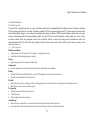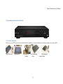
1
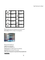
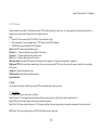
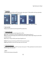
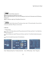
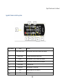
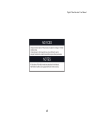
Digital Video Recorder: User Manual USER MANUAL ET16C2E 16 channel CIF Digital Video Recorder 1 Digital Video Recorder: User Manual DVR User’s Installation and Operation Manual Welcome Thank you for purchasing our DVR . This manual is designed to be a reference tool for the installation and operation of your system. Here you can find information about this series, DVR features and functions as well as a detailed menu tree. Before installation and operation, please read the following safeguards and warnings carefully! Important Safeguards and Warnings: 1. Do not place heavy objects on DVR. 2. Do not let any solid or liquid fall into or infiltrate the DVR. 3. Please brush printed circuit boards (PCB‟s), connectors, fans, machine box and so on regularly. 4. Before the dust cleaning, please Switch OFF the power supply and unplug it. 5. Do not disassemble or repair the DVR by yourself. Do not replace the components by yourself. Environment: 1. Please place and use the DVR between 0 – 40 degree Celsius. Avoid direct sunlight. Stay away from heat source. 2. Do not install the DVR in damp environment. 3. Do not use the DVR in smoky and dusty environment. 4. Please ensure that the DVR level installation is in a stable workplace. 5. Please install in ventilated place. Keep the vent clean. 6. Use within the rating input and output scope. 2 Digital Video Recorder: User Manual Table of Contents Contents...................................................................................................................................................................................................................... ..3 1. Product Introduction............................................................................................................................................................................................... ..5 1.1 Product overview............................................................................................................................................................................................ ..5 1.2 Main functions................................................................................................................................................................................................. ..5 2. Open-package check and cable connections.................................................................................................................................................. ........ ..7 2.1 Hard Disk Installation..................................................................................................................................................................................... ..7 3. Basic operation....................................................................................................................................................................................................... 10 3.1 Turn on............................................................................................................................. .............................................................................. 10 3.2 Turn off........................................................................................................................................................................................................... 10 3.3 Login.............................................................................................................................................................................................................. 10 3.4 Preview............................................................................................................................. ............................................................................... 11 3.5 Desktop shortcut menu............................................................................................................................. ....................................................... 11 3.5.1 Main menu ..................................................................................................................................................................................................... .11 3.5.2 Video playback ..................................................................................................................................................................................... ...........12 3.5.3 Record Mode ......................................................................................................................................................................................... ..........14 3.5.4 Alarm output ........................................................................................................................................................................................ ...........14 3.5.5 PTZ control .......................................................................................................................................................................................... ...........15 3.5.6 Color Settings.................................................................................................................................................................................................. 18 3.5.7 TV adjust ......................................................................................................................................................................................................... 18 3.5.8 Logout............................................................................................................................................................................................................. .19 3.5.9 Window switch ............................................................................................................................................................................................. .19 4. Main Menu.............................................................................................................................................................................................................. .20 4.1 Main menu navigation.................................................................................................................................................................................. .20 4.2 Recording function...........................................................................................................................................................................................22 4.2.1 Recording Configuration........................................................................................................................................................................,22 4.2.2 Video playback............................................................................................................................. ............................................................23 4.2.3 Video backup............................................................................................................................. ...............................................................23 4.3 Alarm Function............................................................................................................................. ................................................................... 24 4.3.1 Motion Detect ...................................................................................................................................................................................................24 4.3.2 Video Loss .........................................................................................................................................................................................................25 3 Digital Video Recorder: User Manual 4.3.3 Alarm input........................................................................................................................................................................................................25 4.3.4 Alarm output .....................................................................................................................................................................................................26 4.3.5 Abnormality.......................................................................................................................................................................................................26 4.4 System setup.....................................................................................................................................................................................................26 4.4.1 General setup.....................................................................................................................................................................................................26 4.4.2 Encode setup .....................................................................................................................................................................................................27 4.4.3 Network setup ...................................................................................................................................................................................................28 4.4.4 Network service ................................................................................................................................................................................................28 4.4.5 GUI display .......................................................................................................................................................................................................30 4.4.6 PTZ setup ..........................................................................................................................................................................................................31 4.4.7 Serial port setup ................................................................................................................................................................................................31 4.4.8 Tour setup .......................................................................................................................................................................................................31 4.5 Management tools............................................................................................................................................................................................32 4.5.1 Hard disk management............................................................................................................................................................................32 4.5.2 User management .............................................................................................................................................................................................32 4.5.3 Online user ........................................................................................................................................................................................................33 4.5.4 TV adjust ...........................................................................................................................................................................................................33 4.5.5Auto maintenance ..............................................................................................................................................................................................34 4.5.6 Resume default..................................................................................................................................................................................................34 4.5.7 Upgrade .............................................................................................................................................................................................................34 4.6 System information...........................................................................................................................................................................................35 4.6.1 Hard disk information.......................................................................................................................................................................................35 4.6.2 Code stream statistics .......................................................................................................................................................................................35 4.6.3 Log information ................................................................................................................................................................................................35 4.6.4 Edition information...........................................................................................................................................................................................35 4.7 Shut down system.............................................................................................................................................................................................. 35 5. FAQs and Maintenance.............................................................................................................................................................................................. 36 5.1 FAQs.................................................................................................................................................................................................................. 36 5.2 Maintenance...................................................................................................................................................................................................... 41 Appendix 1.Remote controller operation...................................................................................................................................................................... 42 Appendix 2. Mouse Operation.............................................................................................................................................................................. ........ 43 4 Digital Video Recorder: User Manual 1. Product Introduction 1.1 Product overview The series DVR is designed especially for security and defense field which is outstanding Digital Surveillance product. It introduces embedded LINUX operating system which is more stable. It introduces standard H.264 video compression format and G 711A audio compressed format which ensures the high quality image, low error coding ratio and single frame playing. It introduces TCP/IP network technology which achieves the strong network communication ability and telecommunication ability. The series DVR can be used individually or online applied as a part of a safety surveillance network. With the professional network video surveillance software it achieves the strong network communication ability and telecommunication ability. The series DVR can be applied in the bank, telecom, electric power system, judicial system, factory, storehouse, water conservancy and so on. .1 1.2 Main functions Real-time surveillance Analog interface and VGA interface (VGA interface is equipped selectively). Surveillance function through monitor or display. Storage Special storage format which ensures the data safety. Compression Real time compression which ensures the audio and video signal stable synchronization. Backup Through SATA interface and USB interface such as USB equipment, removable hard disk and so on. Through net download the files in the hard disk. Playback Individual real time video recording as well as searching, playback, network surveillance, recording check, downloading and so on. Multi-Playback mode zooms at arbitrary region. Net operating Through net tele-surveillance in the real time. Tele-PTZ control. Tele-recording and real time playback. Alarm linkage Multi-route relay output which is convenient for the alarm linkage and light control and the sort. Protecting circuits at the alarm input and output interface which protects the main machine from damage. 5 Digital Video Recorder: User Manual Communication interface RS485 interface which fulfills the PTZ control. Standard Ethernet network interface which fulfills the telecommunication function. Intelligent operating Mouse action function. Fast copy and paste operating for the same setting. 6 Digital Video Recorder: User Manual 2. Open-package check and cable connections 2.1 Hard Disk Installation Before you use the DVR for the first time, the HDD should be installed in, 1/2/4 units of HDD can be installed according to the model of DVR. Take off the cover Open the DVR Fix the HDD by housing Cover the housing screen 7 Fix the housi ng, connect the data Digital Video Recorder: User Manual Description of rear panel: Rear panel of 4 channel H.264 DVR: 8 Digital Video Recorder: User Manual Name Description Video input Standard BNC port connected with the Camera. Video output Connected with the video input of the monitor. Name Description VGA VGA video signal output port connected with a VGA port of a computer monitor. Audio output Connected with earphone or cable speaker. Audio input port Connected to audio input device. “485” (AB) External alarm port RS485, it can connect PTZ or decoder, and can Control PTZ via the panel, mouse, remote control and network. Connected with alarm input and output. USB Connected to USB Pen-drive or mouse and used for system software upgrade or video file backup. NET RJ-45 network port connected to network cable and used for remote browse or control. Power Power input is DC 12V/5A (16 Channel DVR). Power input is 12V/3A (4/8 channel DVR). 9 Digital Video Recorder: User Manual 3. Basic operation Note: The button in gray display indicates non-support. 3.1 Turn on Plug the power supply and turn on the power supply switch. Power supply indicator light indicates „turning on‟ of the video r ecorder. After the startup you will hear a beep. The default setting of video output is multiple-window output mode. If the startup time is within the video setting time, the timing video recording function will start up automatically. Then the corresponding channel is shining and the DVR is working normally. Note: 1. Make sure that the input voltage corresponds with the switch of the DVR power supply. 2. Power supply demands: 220V ±10% /50Hz. 3. Suggest using the UPS to protect the power supply under allowable conditions. 3.2 Turn off There are two methods to turn off the DVR. Entering [main menu] and choosing [turn off] in the [turn off the system] option is called soft switching. Pressing the power supply switch is called hard switching. Illumination: Auto resume after power failure. If the DVR is shut down abnormally, it can automatically backup video and resume previous working status after power failure. Replace the hard disk. Before replacing the hard disk, the power supply switch in the rear panel must be turned off. Replace the battery. Before replacing the battery, the setting information must be saved and the power supply switch in the real panel must be turned off. The DVR uses button battery. The system time must be checked regularly. If the time is not correct you must repla ce the battery, we recommend replacing the battery every year and using the same battery type. Note: The setting information must be saved before replacing the battery, otherwise, information will be lost. 3.3 Login When the DVR boots up, the user must login and the system provides the corresponding functions with the user purview. There a re two user settings. The names are 'admin' and 'guest'. These names have no password. 'Admin' is the super user purview; and 'Guest' permissions are preview and video playback. User 'admin' and 'guest' passwords can be revised, while their permissions can‟t be revised. 10 Digital Video Recorder: User Manual Password protection: If the password is continuous wrong three times, the alarm will start. If the password is continuous wrong five times, the account will be locked. (The account can be unlocked through reboot or after half an hour, the account will be unlocked automatically). For your system security, please modify your password after first login. Picture 3.1 Login 3.4 Preview You can right click mouse to choose to switch between the windows. The system date, time and channel name are shown in each v iewing window. The surveillance video and the alarm status are shown in each window. 3.5 Desktop shortcut menu In preview mode you can right click mouse to get a desktop shortcut menu. The menu includes: main menu, video playback, video control, alarm output, PTZ control, color setup, TV adjust, shut down system, window switch. 3.5.1 Main menu When you login, the system main menu is shown as below . Picture 3.2 Main menu Picture 3.3 video playback Picture 3.4 detect the storage 11 Picture 3.5 Recording backup Digital Video Recorder: User Manual 3.5.2 Video playback There are two methods for you to play the video files in the hard disk. 1. In the desktop shortcut menu. 2. Main menu > video recording > video playback. Note: The hard disk that saves the video files must be set as read-write or read-only state. [Listed files] Look up the listed files that accord with the searching criteria. [File information] Look up the found file information. [File backup] Backup the chosen file. Click the button and operate as followed. Note: The storage must be installed before the file backup. If the backup is terminated, the already existing backup can playback individually. Detect: Detect the storage connected with the DVR such as hard disk or universal disk. Erase: Choose the file to delete and click 'Erase' to delete the file. Stop: Stop the backup. Backup: Click 'Backup' button and the dialog box is popped up. You can choose the backup file according to type, channel and time. Remove: Clear the file information. Add: Show the file information satisfying the set file attributes. Start/Pause: Click the 'Play' button to start the backup and click the 'Pause' button to stop the backup. Button Function Play/pause Button Function Backward 12 Digital Video Recorder: User Manual Stop Volume Slow play Fast play Previous frame Next frame Previous file Repeat playback Next file Full screen Cancel: During backup you can exit the page layout to carry out their functions. [File searching]:Search the file according to the searching parameter. Picture 3.6 File searching File type: Set the searching file type. Channel: Set the searching channel. Start Time: Set the searching time scan. Playback control: Refer to the following sheet for more information. Operation hint: Displays the function of the cursor place. NOTE: Frame by frame playback is only performed in the pause playback mode Special Functions: 13 Digital Video Recorder: User Manual Accurate playback: Input time (H/M/S) in the time column and then click 'Play'. The system can operate accurate playback according to the searching time. Local zoom: When the system is in single-window full-screen playback mode, you can drag your mouse in the screen to select a section and then left click mouse to realize local zoom. You can right click mouse to exit. 3.5.3 Record Mode Picture 3.7 Recording Control Interface Picture 3.8 Alarm output Picture 3.9 PTZ Setup Please check current channel status: “o” means it is not in recording status “●” means it is in recording status. You can use desktop shortcut menu or click [main menu] > [recording set] to enter the recording control interface. [Schedule]Record according to the configuration. [Manual] Click the 'All' button and the corresponding channel starts recording, no matter the channel in any state. [Stop] Click the 'Stop' button and the corresponding channel stops recording, no matter the channel in any state. 3.5.4 Alarm output Please check current channel status: “o” means it is not in alarming status “●” means it is in alarming status. You can use d esktop shortcut menu or click [Main menu] > [alarm output] to enter the alarm output interface. [Configuration] Alarm is 'on' according to the configuration. [Manual] Click the 'All' button and the corresponding channel is alarming, no matter the channel in any state. [Stop] Click the 'Stop' button and the corresponding channel stops alarming, no matter the channel in any state. 14 Digital Video Recorder: User Manual 3.5.5 PTZ control Operation interface is as follows. The functions include: PTZ direction control step, zoom, focus, iris, setup operation, tour between spots, trial tour, boundary scan, assistant switch, light switch, level rotation and so on. Note 1. Decoder A(B) line connects with DVR A(B) line. The connection is right. 2. Click [main menu] > [system configuration] > [PTZ setup] to set the PTZ parameters. 3. The PTZ functions are decided by the PTZ protocols. [Step] Set the PTZ rotation range, Default range 1-8. [Zoom]click +/ - button to adjust the zoom multiple of the camera. [Focus]click +/ - Button to adjust the focus of the camera. [Iris] click +/ - Button to adjust the iris of the camera. [Direction control] Control the PTZ rotation, 8 directions control is supportive, (4 directions in front panel is supportive). [High speed PTZ] Full screen shows channel image, left press mouse and control PTZ to rotate, then rotate the mouse to adjust the zoom multiple of the camera. [Setup] Enter the function operation menu. [Window switch] Switch between different windows. Special Function: 1. Preset. Set a location for the preset, calls the preset points, PTZ automatically turns to the set position. 1) Preset option Set a location for the preset, procedure is as follows: Step 1:In picture 3.10, clicking the direction buttons will turn into preset position, click the 'set' button to enter Picture 3.11. Step 2:Click the 'Preset' button, then write the preset points in the input box. Step 3:Click 'Set' button, return to the picture 3.10. Complete setup that is the preset points and preset position corresponds to t he values entered. DEL Preset: After entering preset points, click 'Del Preset' button to remove the preset. 15 Digital Video Recorder: User Manual 2) Preset point calls In picture 3.10, click 'Page switch' button, enter PTZ control interface as shown in picture 3.12. In the input blank, write the preset point number, then click 'Preset' button, PTZ turns to the corresponding preset point. Picture 3.10 Preset Settings Picture 3.11 PTZ Control Picture 3.12 Tour between point settings Picture 3.13 Scan Setup 2. Tour between Points Multiple preset points connected tour line, call tour points, the PTZ run around on the line. 1) Tour between points settings Tour line is connected by multiple preset points, setting procedure is as follows: Step 1: In picture 3.10, the Direction key will turn PTZ to designated location, click 'Set' button to enter Picture 3.13. Step 2: Click 'Tour' button, then write proper values in the 'Preset' box, then click 'Add preset' button and complete settings (al so can add or delete tour which has been set up). Step 3: Repeat step 1 and step 2, until all the points in the preset designated tour is set. Del Preset: Please input preset value in the box, click 'Del Preset' button to remove the preset points. Del Tour: Input the number of tour line, click 'Del Tour' button to remove the tour lines set. 2) The Calls of Tour between Points. In picture 3.10, click 'Page Switch' button, enter PTZ control menu as shown in picture 3.12. Please input the number of tour in the box, then click 'Tour' & PTZ begins to work on the tour line. 3. Pattern PTZ also can work on the preset scan line repeatedly. 16 Digital Video Recorder: User Manual 1) Pattern setup Step 1: In picture 3.10, click 'Set' button, enter picture 3.14. Step 2: Click Pattern button, then enter proper values in the scan box. Step 3: Click Begin button, enter picture 3.10, here you can set the following terms: Zoom, Focus, Iris, Direction and soon click 'Set' button to go back picture 3.14. Step 4: Click 'End' button to complete setup. Click right button of the mouse to exit. 2) Pattern Calls In picture 3.10, click 'Page Switch' button, then enter PTZ control menu as shown in picture 3.12. Please enter the number of the scan in the value box, then click 'AutoScan' button, PTZ begins to work on the scan line. 4. Border Scan 1) Boundary Scan Setup Step 1: In picture 3.10, click Direction button to turn the PTZ to preset direction, then click 'Set' button to enter Picture 3.15, select 'Border' button, then 'left' and return to picture 3.10. Step 2: Please click direction arrows to adjust PTZ direction, click 'Set' button to enter Picture 3.15. Select 'Border', then 'right' and return to picture 3.10. Step 3: You have thus completed the setup of position of left and right boundary. Picture 3.14 Boundary Scan Setup Picture 3.15 Auxiliary Function Control 17 Picture 3.16 PTZ menu settings Picture 3.17 Image colour Digital Video Recorder: User Manual 5. Horizontal Rotating Click Horizontally rotating button, PTZ begins to rotate horizontally (relative to original position of the camera). Click 'Stop' button to stop. 6. Rotate Click on the Horizontal rotating button; PTZ turns around. 7. Reset PTZ restart; all the data clears to 0. 8. Page Switch In picture 3.12, click 'Page Switch' button to enter into picture 3.16, setting auxiliary function. Enter Auxiliary number corresponding to auxiliary switch on the decoder. [Auxiliary Number] The operation of corresponding auxiliary switch according to PTZ agreement. [Page Switch] In picture 3.16, click 'Page Switch' button to enter the Picture 3.17 PTZ Main Menu, the menu itself can be controlled by the Menu control buttons. Enter Menu: Enter PTZ menu. Exit Menu: Exit PTZ menu. Direction Button: The function buttons to choose PTZ menu. Confirm/Cancel: To choose PTZ menu. 3.5.6 Color Settings Set the selective image parameters (current channel for single window display and cursor place for multi-window display). You can use the desktop shortcut menu and enter the interface. The image parameters include: tonality, brightness, contrast, saturation. You can set different parameters at different time sections. 3.5.7 TV adjust Adjust TV output area parameters. You can use the desktop shortcut menu or enter [main menu]> [management tools]> [TV adjust] 18 Digital Video Recorder: User Manual Picture 3.18 TV adjust Picture 3.19 shut down the system 3.5.8 Logout Logout, shut down the system or reboot up. You can use the desktop shortcut menu or enter [main menu]. [logout] Quit the menu. Offer password next entrance [shut down] Quit the password. Turn off the power supply. When press the shutdown button, there is schedule hint. After three seconds, th e system is shut down. Cancel midway is of no effect. [reboot] Quit the system. Reboot up the system. 3.5.9 Window switch Preview in single window/four windows/eight windows/nine windows according to the choice. 19 Digital Video Recorder: User Manual 4. Main Menu 4.1 Main menu navigation Main Menu Function Sub Menu Setup Set the recording configuration, recording type, recording time section. Recording Playback Backup Motion detection Abnormality Video loss Alarm Set recording look-up, recording play, video file storage Detect or format backup equipment, back the selective files Set motion detect alarm channel, sensitivity, area, linkage parameters: defending time section, alarm output, screen hint, recording, PTZ, tour. Set alarm (message or buzzer) for abnormal events such as IP address conflict or full HDD. Set video loss alarm channel, linkage parameters: depending time section, alarm output, screen hint, recording, PTZ, tour. Alarm input Set alarm input channel, equipment type, linkage parameters: defending time section, alarm output, screen hint, recording, PTZ, tour. Alarm output Set alarm output, screen hint, recording, PTZ, tour. Common Configuration Set system time, data format, language, hard disk full time operation, machine number, video format, output made, summer time, stay time. Code Configuration Set main (assistant) coding parameter: code mode, resolving ability, frame rate, code stream control, image quality type, code stream value, frame between value video/audio enable. System configuration 20 Digital Video Recorder: User Manual Network configuration System Configuration Network service PPPOE, NTO, E-Mail purview, DDNS parameter. Output Mode Set channel name, purview hint icon state, transparency, cover area, time title, channel time fold. PTZ configuration System configuration Management tools Set basic network parameters, DHCP and DNS parameters, network high speed download. Set channel, PTZ protocol, address, baud rate, date bit, stop bit, check Serial port configuration Set serial port function, baud rate, date bit, stop bit, check Tour configuration Set tour mode and interval time Hard disk management Set appointed hard disk as read-write disc, read-only disc or redundant disc, clear data, resume date and so on. User management Modify user, group or password. Add user or group. Delete user or group. Online user Break the connection with the already logged in user. Lock the account after break until booting up again. TV adjust Adjust TV upside, downside, nearside, starboard distance Automatic maintenance Set automatic reboot system and automatic deleting files. Resume default Resume setup state : common setup, code setup, recording setup, alarm setup, network setup, network service, preview playback, serial port setup, user management 21 Digital Video Recorder: User Manual System information Shutdown Hard disk information Display hard disk capability and recording time Code stream statistics Logs Display code stream information Version Display edition information Log out, shut down or reboot Clear all log information according to the log video and time 4.2 Recording function 4.2.1 Recording Configuration. Set the recording parameters in the surveillance channel. The system is set for 24 hours consecutive recording in the first startup. You can enter [Main menu] > [Recording function] > [Recording setup] to set. Note: There is at least one read-write hard disk.(refer to chapter 4.5.1) Picture 4.1 recording setup Picture 4.2 detect the equipment Picture 4.3 file backup [Channel] Choose the corresponding channel number to set the channel. Choose the 'All' option to set the entire channels. 22 Digital Video Recorder: User Manual [Redundancy] Choose the redundancy function option to implement the file double backup function. Double backup is writing the video file s in two hard disks. When you do the double backup, make sure there are two hard disks installed. One is read-write disk and the other is redundant disk. (refer to 4.5.1) [Length] Set the time length of each video file. (60 minutes default value) [Pre-Record] Record 30 seconds before the action. (time length is decided by the code stream) [Mode] Set video state: schedule, manual or stop. Schedule: Record according to the set video type (regular, detection and alarm) and time section. Manual: Click the button and the corresponding channel starts recording, no matter the channel in any state. Stop: Click the stop button and the corresponding channel stops recording, no matter the channel in any state. [Time section] Set the time section of common recording. The recording will start only in the set range. [Recording type] Set recording type: regular, detection or alarm. Regular: Perform the regular recording in the set time section. The video file type is “R”. Detection: Trigger the “motion detect”, “camera mask” or “video loss” signal. When above alarm is set as opening recording, the “detecti on recording” state is on. The video file type is “M”. Alarm: Trigger the external alarm signal in the set time section. When above alarm is set as opening recording the “detection recording” state is on. The video file type is “A”. Note: Refer to chapter 4.3 to set corresponding alarm function. 4.2.2 Video playback Refer to chapter 3.5.2. 4.2.3 Video backup You can back up the video files to external storage through setup. Note: The storage must be installed before the files backup. If the backup is terminated, the already existing backup can playback individually. [Detect] Detect the storage connected with the DVR such as hard disk or universal disk. [Erase] Choose the file to delete and click erasure to delete the file. [Stop] Stop the backup. [Backup] Click backup button and the dialog, box is popped up. You can choose the backup file according to the type, channel and time. 23 Digital Video Recorder: User Manual Remove: Clear the file information. Add: Show the file information satisfying the set file attributes. Start/Pause: Click the play button to start the backup and click the pause button to stop the backup. Cancel: During backup you can exit the page layout to carry out other functions. 4.3 Alarm Function Alarm functions include: motion detect, video loss, alarm input and alarm output. 4.3.1 Motion Detect When system detects the motion signal that reaches the set sensitivity, the motion detect alarm is on and the linkage function is turned on. Picture 4.4 motion detect Picture 4.5 set the area Picture 4.6 set the time section Picture 4.7 PTZ Activation [Channel number] Choose the set motion detect channel. [Enable] Means that the motions detect function is on. [Sensitivity] Choose in the six options according to the sensitivity. [Area] Click setup and enter the set area. The area is divided into PAL22X18. Green block means the current cursor area. Yellow block means the dynamic detect defensive area. Black block means the unfenced area. You can set the area as followed. Drag the mouse and draw the area. [Period] Trigger the motion detect signal in the set time section. You can set according to week or set uniformly. Each day is divided into four time sections. Means the set valid. [Interval] Only one alarm signal is turned on (even there are several motion detect signals) in the set interval. 24 Digital Video Recorder: User Manual [Alarm output ] Start the external equipment of corresponding linkage alarm when the motion detect alarm is turned on. [Delay] Delay a few moments and stop when the alarm state is turned off. The range is 10-300 seconds. [Record channel] Choose the recording channel (multiple options supportive). Trigger the video signal when the alarm is turned on. Note: Set in the [recording channel] and perform the linkage recording. Start detecting video files in the corresponding t ime section. [PTZ Activation] Set the PTZ linkage when the alarm is turned on. Note: PTZ linkage is set in the [shortcut menu] > [PTZ control]. Set the tour between spots, trail tour and so on . [Show message] Pop the alarm information dialog box in the local host computer screen. [E-Mail] Means sending an E-mail to user when the alarm is turned on. Note: Set in the [network service] and send an E-Mail. Picture 4.8 video loss Picture 4.9 alarm input Picture 4.10 Abnormality 4.3.2 Video Loss When the equipment cannot obtain the channel video signal , the video loss alarm is turned on and the linkage function is turned on. Set method: refer to chapter 4.3.1. 4.3.3 Alarm input When the equipment obtains the external alarm signal, the alarm function is turned on. Set method: refer to chapter 4.3.1. 25 Digital Video Recorder: User Manual 4.3.4 Alarm output Refer to chapter 3.5.4. 4.3.5 Abnormality Analyzing and inspecting current software and hardware of the device: When some abnormal events happen the device will make a relative answer such as show message and buzzer. [Event type] Selecting abnormality you want to inspect. [Enable] Select it to make sure abnormal function workable. [Show message] Automatically alarm cue dialog box come out of the main screen. [Buzzer] In-built buzzer will ring when alarm occurs. 4.4 System setup Set the system parameters such as general setup, code setup, network setup, network service, output mode, PTZ control, serial port setup and alternate patrol setup. 4.4.1 General setup [System time] Set system data and time. [Data format] Choose the data format: YMD, MDY, DMY. [Date separator] Choose list separator of the data format. Picture 4.11 regular setup Picture 4.12 week setup Picture 4.13 date setup 26 Digital Video Recorder: User Manual [Time format] Choose time format: 24-hour or 12-hour. [Language] English or Chinese. [Hard disk full] Choose stop: Stop recording when the hard disk is full. Choose cover: Cover the earliest recording files and continue recording when the hard disk is full. [DVR Number] Only when the address button in the remote controller and the corresponding DVR number is matched, the remote operation valid. [Video format] PAL or NTSC. 4.4.2 Encode setup Set the video/audio code parameter: video file, remote monitoring and so on. Set every independent channel‟s coding parameter in the left part and set the combination coding parameter in the right port. Note: Combination coding introduces video compression technique which combines and compresses multi-channel‟s video to a special channel. Its main using: multi-channel playback simultaneously, DUN multi-channel real-time surveillance, mobile surveillance and so on. [Channel ] Choose the channel number. [Code format]Standard H.264. [Resolution] Resolution type: CIF . [Frame rate] P: 1 Frame/s- 25 frames/s. [Code stream control] You can choose limited code stream or variable code stream. When you choose the variable code stream there are six image quality options. [Code stream value] Set the code stream value to modify the image quality. The larger code stream value the better image quality. [Video/ Audio] When the icons are all in reverse displayed, the video file is video and audio multiplex stream. 27 Digital Video Recorder: User Manual Picture 4.14 network setup Picture 4.15 code setup Picture4.16 network service Picture 4.17 PPPOE setup 4.4.3 Network setup [Network card] You can choose cable network card or wireless network card. [DHCP enable] Obtain IP address automatically. Note: DHCP server is pre-installed. [IP address] Set the subnet mask code. Default: 192.168.1.10. [Subnet mask code] Set the subnet mask code. Default: 255.255.255.0. [Default gateway] Set the default gateway. Default: 192.168.1.1. [DNS setup] Domain name server, it translates the domain name into IP address. The IP address is offered by network provider. The address must be set and reboot then it works. [TCP port] Default: 34567. [HTTP port] Default: 80. [HS download]: The high speed download option can be enabled. [Network transmission strategy] There are three strategies: self-adaption, image quality, precedence and fluency precedence. The code stream will adjust according to the setup. Self adaption is the trade-off between the image quality precedence and fluency precedence. Fluency precedence and self-adaption are valid only when the assistant code stream is turned on. Otherwise image quality precedence is valid. 4.4.4 Network service Choose the network service option and click the set button to configure the advanced network functions or double click the service button to configure the parameters. [PPPOE setup] 28 Digital Video Recorder: User Manual Input the user name and password that ISP (Internet service provider) provides. After saving it reboot up your system. Then the DVR will build a network connection based on PPPOE. The IP address will change into dynamic IP address above operation is well done. Operation: After PPPOE dialing successfully look up the IP address in the [IP address] and obtain the current IP address. Then use this IP address to visit the DVR through user port. [NTP setup] The NTP server must be installed in the PC. Picture 4.18 NTP setup Picture 4.19 EMAIL setup Picture 4.20 IP purview setup Host computer IP: Input the IP address installed NTP server. Port: Default 123. You can set the port according to NTP server. Time zone: London GMT+0, Berlin GMT+1, Cairo GMT+2, Moscow GMT+3, New Delhi GMT+5, Bangkok GMT+7, Hong Kong Beijing GMT+8, Tokyo GMT+9, Sydney GMT+10, Hawaii GMT-10, Alaska GMT-9, Pacific time GMT-8, American mountain time GMT-7, American mid time GMT-6, American eastern time GMT-5, Atlantic time GMT-4, Brazil GMT-3, Atlantic mid time GMT-2. Update cycle: The same with the NTP server check interval. Default: 10 minutes. [DDNS] It is the abbreviation of dynamic domain name server. Local domain name: Provide the domain name registered by DDNS. User name: Provide the account registered by DDNS. Password: Provide the password registered by DDNS. When the DDNS is successfully configured and start, you can connect the domain name in the IP address. Note: The DNS must be configured in the network setup. 29 Digital Video Recorder: User Manual Picture 4.21 DNS setup Picture 4.22 Mobile Monitor Setup Picture 4.23 Output Mode [Mobile Monitor Setup] To visit the device by mobile, please make a router mapping of this port and use CMS to monitor and operate it by protocol. [Enable] Select it to make sure abnormal function workable. [Port] It‟s a port of mobile monitoring which you ned to make a router mapping of if want to visit it by mobile. 4.4.5 GUI display 【Channel name】■ Click the channel name modify button and enter the channel name menu. Modify the channel name. The 16 Chinese characters and 25 letters are supportive. 【Time title】■ means the selective state. Display the system data and time in the surveillance window. 【channel title】■ means the selective state. Display the system channel number in the surveillance window. 【Recording status】■ means the selective state. Display the system recording status in the surveillance window. 【alarm status】■ means the selective state. Display the system alarm status in the surveillance window. 【code stream information】■ means the selective state. The ninth window displays the code stream information in the nine-window preview status. 【transparency】■ Choose the background image transparency. The range is 128~255. 【resolution】■ set display resolution. 【channel】■ Choose the set code output channel number. 30 Digital Video Recorder: User Manual 4.4.6 PTZ setup [Channel] Choose the dome camera input channel. [Protocol] Choose the corresponding dome protocol, (PELCOD as an example). [Address] Set as the corresponding dome address. Default 1. (Note: The address must be consistent with the dome address.) [Baud rate] Choose the corresponding dome baud rate length. You can control the PTZ and vidicion. Default: 115200. [Date bit] Include 5-8 options. Default: 8. [Stop bit] Include 2 options. Default: 1. [Parity] Include odd check, even check, sign check, blank check. Default: void. 4.4.7 Serial port setup Picture 4.24 PTZ setup Picture 4.25 Serial Port Setup Picture 4.26 Tour Setup [Serial port function] Common serial port is used to debug and update program or set up specific serial port. [Baud rate] Choose the corresponding baud rate length. [Data bit] Include 5-8 options. [Stop bit] Include 2 options. [Parity] Include odd check, even check, sign check, blank check. 4.4.8 Tour setup Set the tour display. Means that the tour mode is turned on. You can choose the single window, four windows, nine windows, si xteen windows tour display or single display. [Interval] Set the tour switch interval. The set range is 5-120 seconds. 31 Digital Video Recorder: User Manual Note: / means turn off/on the tour. 4.5 Management tools 4.5.1 Hard disk management Configure and manage the hard disk. The menu displays current hard disk information: hard disk number, input port, type, status and overall capability. The operation include: setup the write-read disk, read-only disk, redundant disk, hard disk format, resume default. Choose the hard disk and click the right function button to execute. Note: write read disk: The equipment can write or read data. Read-only disk: The equipment can read data but cannot write data. Redundant disk: Double backup the video files in the write-read disk. Picture4.27 hard disk management Picture 4.28 user management Picture 4.29 modify password Picture 4.30 add user 4.5.2 User management Manage the user purview. Note: 2) The char length is 8 bytes at most for the following user and user group name. the blank or behind the char string is invalid. The middle blank is valid. Legal char include: letter, number, underline, subtraction sign, dot. 3) There is no limit in the user and user group. You can add or delete the user group according to user definition. 32 Digital Video Recorder: User Manual The factory setup include: user /admin. You can set the group as you wish. The user can appoint the purview in the group. 4) The user management include: group/user. The group and user name cannot be the same. Each user only belongs to one group. [Modify user] Modify the existing user attribute. [Modify group] Modify the existing group attribute. [Modify password] Modify the user password. You can set 1-6 bit password. The blank ahead or behind the char string is invalid. The middle blank in the char string is valid. Note: The user who possesses the user control purview can modify his/her own or other user password. Once the group is chosen, the user purview is the subclass of the group. We recommend that the common user‟s purview is lower than the advanced user. [Add group] Add user group and set the purview. There are different criteria: shut down the equipment, real time surveillance, playback, recording setup, video file backup and so on. Picture 4.31 add group Picture 4.32 Delete group [Delete user] Delete the current user. Choose the user and click delete user button. [Delete group] Delete the current group. Choose the group click the 'Delete group' button. 4.5.3 Online user Look up the network user information in the local DVR. You can choose the network user and cut the connection. Then the user is locked until next boot-strap. 4.5.4 TV adjust Refer to chapter 3.2.7. 33 Digital Video Recorder: User Manual Picture 4.33 Resume default Picture 4.34 upgrade information Picture 4.35 hard disk statistics 4.5.5Auto maintenance The user can set the auto reboot time and auto file deleting time limit. 4.5.6 Resume default The system resume to the default setup. You can choose the items according to the menu. 4.5.7 Upgrade Code stream Picture 4.37 log information Picture 4.38 edition information Picture 4.36 [Upgrade] Choose USB interface. [Upgrade file] Choose the file which needs upgraded. 34 Digital Video Recorder: User Manual 4.6 System information 4.6.1 Hard disk information Display the hard disk state: hard disk type, overall capability, residual capability, the recording time and so on. Clue: Means that the hard disk is normal. X means that the hard disk is broken down. – means that there is no hard disk. If the user needs to change the damaged hard disk, you must shut down the DVR and take up all the damaged hard disks then install a new one. * behind serial number means the current working disk such as 1*. If the corresponding disk is damaged, the information will display “?”. 4.6.2 Code stream statistics Display the code stream (Kb/s) and hard disk capability (MB/s) in real time. It displays as the wave sketch map. 4.6.3 Log information Look up system log according to the set mode. Log information include: System operation, configuration operation, data management, alarm affair, recording operation, user management, file management and so on. Set the time section to look up and click the look up button. The log information will display as a list. (one page is 128 items) Press Page up or Page down button to look up and press delete button to clear all the log information. 4.6.4 Edition information Display the basic information such as hardware information, software edition, issue data and so on. 4.7 Shut down system Refer to chapter 3.5.8. 35 Digital Video Recorder: User Manual 5. FAQs and Maintenance 5.1 FAQs If the problems are not listed, please contact the local service or call the HQ service. We are willing to offer the service. 1. The DVR cannot boot up normally. Possible reasons are as followed: The power supply is not correct. Switch power supply line is not in good connection. Switch power supply is damaged. The program uploading is wrong. The hard disk is damaged or the hard disk lines are broken. The front panel is damaged. The main board of the DVR is damaged. 2. The DVR reboots automatically or stops working after boot up a few minutes. Possible reasons are as followed: The input voltage is not stable or too low. The hard disk is damaged or the hard disk lines are broken. The power of the switch power supply is low. Frontal video signal is not stable. Bad heat radiator or too much dust or bad running circumstances for the DVR. The SATA port of main board is damaged. 3. System cannot detect hard disk. Possible reasons are as followed: The hard disk power supply line is not connected. The cables of the hard disk are damaged. The hard disk is damaged. The SATA port of main board is damaged. 4. There are no video outputs in single channel or multiple channels and all channels. Possible reasons are as followed: The program is not matched. Please update the program. The image brightness is all 0. Please resume the default setup. 36 Digital Video Recorder: User Manual There is no video input signal or the signal is too weak. The channel protection or the screen protection is set. The hardware of the DVR is damaged. 5. Real-time image problems such as the image color or the brightness distortion. Possible reasons are as followed: When using the BNC output, the option between the N mode or PAL mode is wrong and the image becomes black and white. The DVR is not matched the monitor impedance. The video transmission distance is too far or the loss of the video transmission line is too large. The color and brightness setting of the DVR is wrong. 6. I cannot find the video files in local playback mode. Possible reasons are as followed: The data line of the hard disk is damaged. The hard disk is damaged. Update the different program with the origin program files. The recording is not on. 7. The local video is not clear. Possible reasons are as followed: The image quality is too bad. the reading program is wrong. Reboot up the DVR. The data line of the hard disk is damaged. The hard disk is damaged. The hardware of the DVR is damaged. 8. There is no audio signal in the surveillance window. Possible reasons are as followed: It is not an active tone arm. It is not an active squad box. The audio lines are damaged. The hardware of the DVR is damaged. 9. There is audio signal in the surveillance window but no audio signal in the playback state. 37 Digital Video Recorder: User Manual Possible reasons are as followed: Settings: the audio is not chosen. The according channel is not connected with the video. 10. The time is wrong. Possible reasons are as followed: Setting is wrong. The battery is in bad connection or the voltage is too low. The oscillation is damaged. 11. The DVR cannot control the PTZ. Possible reasons are as followed: There is something wrong with the frontal PTZ. The setting, connection or the installation of the PTZ decoder is not correct. The connections are not correct. The PTZ setting of the DVR is not correct. The protocols of the PTZ decoder and the DVR are not matched. The address of the PTZ decoder and the DVR are not matched. When multiple decoders are connected, the far port of the PTZ decoder line A(B) must connect a 120 ohms resistance to reduce the reflection otherwise the PTZ control is not stable. The distance is too far. 12. The motion detect is not working. Possible reasons are as followed: The time range set is not correct. The motion detect area set is not correct. The sensitivity is too low. Limited by some hardware edition. 13. I cannot login via web. Possible reasons are as followed: The system is Windows 98 or windows me. We recommend updating to Windows 2000sp4 or higher edition or installing the software for low edition. ActiveX is hold back. 38 Digital Video Recorder: User Manual The edition is not exceeded dx8.1. Update the display card driver. Network connection failure. Network setting issues. Invalid password or user name. The user edition is not matched the DVR program edition. 14. The image is not clear or there is no image in network preview state or video file playback state. Possible reasons are as followed: Network is not stable. The user machine is resource limited. The region shelter or channel protection is set. Choose the play-in team mode in the network setup of DVR. The user has no surveillance purview. The real-time image of the hard disk recording machine itself is not clear. 15. Network connection is not stable. Possible reasons are as followed: Network is not stable. IP address is conflicted. MAC address is conflicted. The network card of the computer or the hard disk recording machine is bad. 16. There is something wrong with the USB backup or writing a CD. Possible reasons are as followed: The rewritable machine and the hard disk are shared the same data lines. The data is too much. Please stop recording and backup. The data exceeds the backup storage. The backup equipment is not compatible.‟ The backup equipment is damaged. 17. The keyboard cannot control the DVR. Possible reasons are as followed: The serial port of the DVR is not set correctly. 39 Digital Video Recorder: User Manual The address is not correct. When multiple transformers are connected, the power supply is not large enough. Please give each transformer individual power supply. The distance is too far. 18. Alarm cannot be recessional. Possible reasons are as followed: The setting of the alarm is not correct. The alarm output Is turned on manually. The input machine is damaged or the connections are not correct. There are some problems for specific program edition, please update the program. 19. Alarm is not working. Possible reasons are as followed: The setting of the alarm is not correct. The connection of the alarm is not correct. The alarm input signal is not correct. An alarm is connected with two loops synchronously. 20. The remote controller is not working. Possible reasons are as followed: The remote control address is not correct. The remote control distance is too far or the angle is too large. The battery is used up. The remote controller or the front panel of the recording machine is damaged. 21. The storage time is not enough. Possible reasons are as followed: Front vidicon quality is bad. The lens is too dirty. The vidicon is in backlighting installation. The hard disk capability is not enough. The hard disk is damaged. 22. The downloading file cannot play. Possible reasons area as followed: There is no media player. 40 Digital Video Recorder: User Manual There is no DX8.1 software or higher edition. There is no DivX 503 bundle.exe file to play AVI video files. The DivX503bundle.exe and ffdshow-20041012.exe files must be installed in the windows XP system. 23. I cannot remember the advanced code or network in the local menu operation. Please contact the local service or call the HQ service. We will offer the service according the machine type and the program. 5.2 Maintenance 1. Please brush printed circuit boards, connectors, fans, machine box and so on regularly. 2. Please keep the grounding well done to prevent the video or audio signal interfered and the DVR from static or inductive electricity. 3. Do not pull out the video signal line or RS-232 port with the power on. 4. Do not use the TV in the local video output port(VOUT) of DVR. It will damage the video output circuit easily. 5. Do not turn off the switch directly, please use the turn-off function in the menu or press the turn-off button in the panel (3 seconds or longer) to protect the hard disk. 6. Please keep the DVR away from heat resource. 7. Please keep the DVR ventilated for better heat radiator. Please check the system and maintain regularly. 41 Digital Video Recorder: User Manual Appendix 1.Remote controller operation Serial number Name Function (1) Multi-window button (2) Numeric button (3) 【Esc】 Same function as 【Esc】 button in the front panel (4) Direction button Same function as direction button in the front panel (5) Record control (6) Record mode (7) ADD (8) FN Same function as Multi-window button in the front panel Code input/ number input/ channel switch Control the record Same function as “Record mode” Input the number of DVR to control it Assistant function 42 Digital Video Recorder: User Manual Appendix 2. Mouse Operation *Take right hand as an example The mouse in USB connection is supportive. Operation Function Double click one item in the file list to playback the video Double click the playback video to zoom in or out the screen Double left click Press middle button Double click the channel to make it full screen display Add or subtract number in the number setting Switch the items in the combo box Page up or down in the list Double click again to resume the multiwindow display Move mouse Choose the widget or move the item in the widget Left click Choose the according function in the menu Drag mouse Set the motion detect area Right click Pop desktop short cut menu in preview state Set the cover area Current short cut menu in the menu 43 Digital Video Recorder: User Manual INFORMATION ON E-WASTE HANDLING AND MANAGEMENT Dear Customer, The Ministry of Environment and Forests have published The E-waste (Management and Handling ) Rules 2010 which comes in effect from 1st May 2012. E-waste is defined as any electrical or electronic component of products in whole or in part , or rejects from their manufactur ing or repair process which are intended to be discarded. These rules apply to every producer, consumer or bulk consumer involved in the manufacture, sale, purchase and processing of electrical and electronic equipment or components as specified in Schedule 1 (please refer to our website www.godrej.com in the „Good & Green‟ section of CSR module for more details). Under these rules , specific roles and responsibilities are defined for producers , consumers and recyclers handling and mana ging E-waste. E-waste is to be managed in an environmentally sound manner which means, taking steps to ensure that health and environment are protected from adverse effects of hazardous substance contained in such wastes. Rule 6 of the E-waste (Management and Handling) Rules 2010 states that bulk consumers of electrical and electronic equipment shall be responsible for recycling of the e-waste generated by them. Bulk consumer means bulk users of electronic and electrical equipment such as Central Government or State Government Departments, public sector undertakings, banks, educational institutions, multinationa l organizations, international agencies, private companies that are registered under the Factories act 1948 and Companies act 19 56. The bulk consumers have to ensure that the e-waste generated by them is channelized to authorized collection centers or is taken back by the producers. They shall maintain records of E-waste generated by them in Form 2 and make such records available for scrutiny by the State pollution control or the Pollution control Committee concerned. All consumers of electrical and electronic equipment irrespective of their status as bulk consumers or not , shall ensure that E-waste generated by them is channelized to authorized collection center(s) or registered dismantler(s), or recycler(s) or is returne d to the pickup/take back services provided by the producers. (Please refer to our website www.godrej.com in the „Good & Green‟ section of CSR module for more details). All our products intended to be recycled under the category of E-waste (as defined above) carry a label or stamp of the WEEE symbol (A wheelie bin with a cross) , which states that it falls under the hazardous waste category and is not to be disposed along wit h normal garbage. We seek your support in ensuring environmentally sound management of E-waste and aid us in sustaining our earth‟s natural resources and maintaining the earth‟s green cover intact for the benefit of our future generations. 44 Digital Video Recorder: User Manual 45