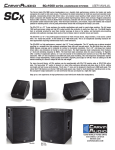
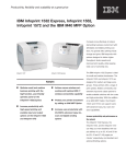
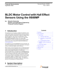
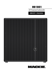
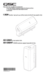
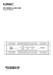
1
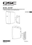
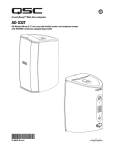
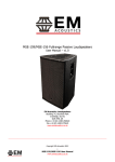
AcousticDesignTM Surface-mount Loudspeaker User Manual
AD-S28Tw
Dual 200 mm (8 in) Bandpass Subwoofer
EN
*TD-000287-00-A*
TD-000287-00-B
important safety precautions
EN
1 - Read these instructions.
2 - Keep these instructions.
3 - Heed all warnings.
4 - Follow all instructions.
5 - Clean only with a dry cloth.
6 - Install in accordance with all QSC instructions and documentation. Suspension and mounting should be attempted only by those
who are trained and skilled in safe suspension and mounting practices
7 - Do not install near any heat sources such as radiators, heat registers, stoves, or other apparatus (including amplifiers) that
produce heat.
8 - Only use attachments/accessories from QSC Audio Products, LLC.
9 - Use only with mounts or brackets specified by QSC Audio Products, LLC.
10 - Refer all servicing to qualified personnel. Servicing is required when the apparatus has been damaged in any way.
The lightning flash with the arrowhead symbol within an equilateral triangle is intended to alert the user to the presence
of uninsulated “dangerous” voltage within the product’s enclosure that may be of sufficient magnitude to constitute a
risk of shock to humans.
The exclamation point within an equilateral triangle is intended to alert the user to the presence of important operating
and maintenance (servicing) instructions in this manual.
WARNING! Before placing, installing, rigging or suspending any loudspeaker product, inspect all hardware,
suspension, cabinets, transducers, brackets and associated equipment for damage. Any missing , corroded,
deformed, or non-load rated component could significantly reduce the strength of the installation and should
be immediately corrected. Use only hardware which is rated for the loading conditions of the installation
and any possible short-term unexpected overloading. Never exceed the rating of the hardware or equipment. Consult a licensed, professional engineer when any doubt or questions arise regarding a physical
equipment installation.
Warranty (USA only; other countries, see your dealer or distributor)
Disclaimer
QSC Audio Products, LLC is not liable for any damage to amplifiers or any other equipment that is caused by negligence or improper installation
and/or use of this loudspeaker product.
QSC Audio Products 3 Year Limited Warranty
QSC Audio Products, LLC (“QSC”) guarantees its products to be free from defective material and/or workmanship for a period of three (3) years
from the date of sale and will replace defective parts and repair malfunctioning products under this warranty when the defect occurs under normal
installation and use - provided the unit is returned to our factory or one of our authorized service stations via prepaid transportation with a copy
of proof of purchase (i.e., sales receipt). This warranty provides that the examination of the returned product must indicate, in our judgement, a
manufacturing defect. This warranty does not extend to any product which has been subjected to misuse, neglect, accident, improper installation ,
or where the date code has been removed or defaced. QSC shall not be liable for incidental and/or consequential damages. This warranty give you
specific legal rights. This limited warranty is freely transferable during the term of the warranty period.
Customer may have additional rights, which vary from state to state.
In the event that this product was manufactured for export and sale outside of the United States or its territories, then this limited warranty shall
not apply. Removal of the serial number on this product, or purchase of this product from an unauthorized dealer will void this limited warranty.
Periodically, this warranty is updated. To obtain the most recent version of QSC’s warranty statement, please visit www.qscaudio.com.
Contact us at 800-854-4079 or visit our website at www.qscaudio.com.
© Copyright 2008, QSC Audio Products, LLC
QSC® is a registered trademark of QSC Audio Products, LLC
“QSC” and the QSC logo are registered with the U.S. Patent and Trademark Office
All trademarks are the property of their respective owners.
2
Introduction
Congratulations and thank you for your purchase of this subwoofer. The AD-S28Tw model offers excellent acoustic performance in an easy-to-install and attractive enclosure. Please review these instructions and carefully follow the recommendations. Consult a licensed installation professional if you are uncertain about any mounting issues.
The AD-S28Tw features dual 8” (200 mm) low frequency (LF) drivers in a ported bandpass enclosure. The AD-S28Tw is
equipped with an audio transformer suitable for 70V and 100V distributed systems, as well as a tap-selector switch which
can bypass the transformer for 8 ohm applications. The AD-S28Tw also includes a bypassable 120Hz low pass filter. The
marine-grade plywood enclosure may be used in floor-standing as well as yoke mounted and suspended applications.
What’s Included
Your surface mount subwoofer includes:
- the loudspeaker cabinet with grille
- extra grille backing foam sheet
- steel yoke bracket
- steel suspension point shear plates (x3)
- steel M6 forged shoulder eyebolts (x4)
- hex head / phillips-head M6 bolts (x3)
- flat washers (x4)
- rubber yoke mounting gaskets (x2)
- rubber feet with integrated attachment bolts (x4)
Features
1 - Marine grade plywood enclosure, painted
2 - ABS grille endcaps
3 - Steel grille with foam backing
4 - Rotatable QSC logo badge
5 - Integrated M6 suspension points
6 - Input cup with rotating door (see detail)
7 - Rubber feet (shown attached)
8 - Service access panel
9 - Low Pass Filter Switch
10 - Transformer tap switch
11 - Input cup door (shown in open position)
12 - Input screw terminals
9
EN
1
2
5
3
4
10
6
12
8
11
3
7
Installation Options
The AD-S28Tw has been designed for installation flexibility. The subwoofer may be mounted using a number of different
suspension techniques, as well as being easily shelf or floor mounted. The QSC logo on the grille is rotatable to accommodate horizontal or vertical orientation. While low frequency products do not have directional dispersion characteristics, all of
the sonic energy produced by this subwoofer exits the cabinet through the port due to the ported bandpass design. For that
reason, the port (located behind the grille) must not be physically blocked by anything, and should not be placed within
twelve (12) inches of any objects larger than 3 to 4 inches (75 to 100 mm).
When the subwoofer is floor or shelf standing it is recommended that the rubber feet be attached.
For suspended installations, the enclosure can be attached with flypoints or the included yoke bracket. The enclosure can be
oriented in multiple positions when suspended:
EN
Attaching the Feet
Locate the four M6 attachment points on the bottom of the sub. Consult the following illustrations and pay careful attention
to which attachment points are correct.
Remove the screws from the selected attachment points using a #2 phillips-head screw driver or electric driver. Remove only
the four screws for the attachment of the feet. DO NOT REMOVE ANY OTHER SCREWS. If a screw hole is left open, it
will create an airleak which will cause noise and compromise the performance of the cabinet.
Screw the rubber feet into the attachment point. It should not require significant force to rotate the foot if the threads are
properly engaged. If the foot is not screwing in easily, remove it and engage it in the threads again.
Do not use any tools for installation of the feet. The rubber may be damaged if a tool is used.
Continue rotating the foot until it makes contact with the cabinet. Only hand generated force is necessary to properly seal
the hole and keep the foot screwed in.
Once the feet are attached, place the subwoofer in the desired location.
4
Mounting the Subwoofer Using the Yoke
The yoke can be used to mount the subwoofer either on a vertical surface, like a wall, or from an overhead surface, like
a ceiling or ceiling beams. In either case, the attachment points on the enclosure for securing the yoke are the same. The
yoke is designed to attach to only two sides of the cabinet and cannot be attached to any other surfaces. The yoke features
slots to allow for either maximum rotation of the cabinet, or for minimum separation between the cabinet and the mounting
surface. Consult the following illustrations.
EN
It is recommended that the yoke be attached to the mounting surface prior to attaching the yoke to the subwoofer enclosure. The yoke is designed to allow attachment to the mounting surface with mounting points ranging from 5.5 in (140 mm)
to 6.5 in (165 mm) apart.
1 - Remove the screws from the selected attachment points using a #2 phillips-head screw driver or electric driver. Remove
only the two screws that will be used for the attachment of the yoke. DO NOT REMOVE ANY OTHER SCREWS. If a
screw hole is left open, it will create an airleak which will cause noise and compromise the performance of the cabinet.
2 - Remove the adhesive backing from the rubber pad and attach the pad to the cabinet by pressing the adhesive coated
side against the cabinet. Make sure not to obstruct the attachment holes. The adhesive will hold the pad in place as you
mount the enclosure to the yoke.
3 - Align the yoke with the attachment points on the subwoofer and place the attachment hardware according to the illustration.
Hex-head / phillips-head M6 Bolt
Lock washer
Flat washer
Adhesive rubber pad (affixed to enclosure)
4 - Tighten the hex-head/phillips-head bolts enough to hold the subwoofer in place but loose enough to rotate with minimum
force. Check the alignment of the subwoofer for best desired appearance. As long as the port is not blocked, the alignment
of the subwoofer will not affect performance. Once positioned, tighten the bolts so that the subwoofer will not rotate with
force.
The yoke must be secured to structure that is capable of supporting the weight of the subwoofer and must be connected using load rated hardware.
Consult a licensed, professional engineer when any doubt or questions arise regarding a physical equipment installation.
Once the subwoofer is secured in position, the QSC logo can be rotated if desired. If the logo is difficult to rotate the first
time, a tool may be required. A small flat-head screw driver is recommended. Gently work the tool between the logo badge
and the grille to allow rotation. Exercise care to avoid scratching the grille surface.
5
Any unused attachment point can be used as a safety/seismic secondary attachment. Attach an eyebolt to an available attachment point according to the section of the manual titled: Suspending the Subwoofer Using Eyebolts and
Shear Plates. Be sure to leave less than 12 in (300 mm) of slack in the secondary attachment cable.
The safety/seismic secondary attachment must be secured to structure that is capable of supporting the weight of the subwoofer and must be connected using load rated hardware.
Suspending the Subwoofer Using Eyebolts and Shear Plates
EN
The subwoofer can be suspended using the included eyebolts. There are three possible orientations for installing the subwoofer this way.
1. Port facing laterally, subwoofer in “wide” orientation
2. Port facing laterally, subwoofer in “narrow” orientation
3. Port facing down
For each of these orientations, the points for eyebolt and shear plate attachment are very specific. Please consult the following illustrations to understand each orientation and pay careful attention to which attachment points are correct.
6
The locations of the eyebolts were designed to suspend the subwoofer using the fewest number of attachment points.
Where possible there are only three attachment points to be used. These points are located so that the triangle they form
“encloses” the center of gravity and the subwoofer will balance with all three points suspended. In some cases, one or
more of the attachment points is not on a cabinet side that is facing up. In these cases DO NOT USE AN EYEBOLT. In this
position, the eyebolt will be in shear and the eyebolt is greatly derated in this use. For these attachment points a SHEAR
PLATE MUST BE USED FOR SUSPENDING the subwoofer.
Remove the screws from the selected attachment points using a #2 phillips-head screw driver or electric driver. Remove
only the screws that will be used for the attachment eyebolts or shear plates. DO NOT REMOVE ANY OTHER SCREWS.
If a screw hole is left open, it will create an airleak which will cause noise and compromise the performance of the cabinet.
Eyebolts
Screw the eyebolt into the attachment point. It should not require significant force to rotate the eyebolt if the threads are
properly engaged. If the eyebolt is not screwing in easily, remove it and engage it in the threads again.
Continue rotating the eyebolt until it makes contact with the cabinet. Once the eyebolt shoulder has made contact with the
cabinet, continue to rotate it until it reaches the desired alignment with the cabinet. If necessary, use a tool such as a long
handheld screwdriver to tighten it. Place the blade of the screwdriver through the eyebolt and use it to rotate the eyebolt.
It is not necessary to tighten the eyebolt to the point that it cannot rotate any further. Once the shoulder has made contact
with the enclosure, any further tightening is actually cutting the shoulder of the eyebolt in to the wood of the cabinet. This
“cutting in” coupled with the tension of suspension on the eyebolt will prevent the eyebolt from loosening once the cabinet
is suspended.
The eyebolts must be secured to structure that is capable of supporting the weight of the subwoofer and must be connected using load rated hardware.
Consult a licensed, professional engineer when any doubt or questions arise regarding a physical equipment installation.
Shear Plates
Align the mounting hole of the shear plate with the enclosure attachment point with the rubber pad between the plate and
the cabinet. Place the attachment hardware according to the illustration. Tighten the hex-head bolts enough to hold the shear
plate in place but leave it just loose enough to rotate with minimum force. Check the alignment of the shear plate so that it is
perpendicular to the cabinet. Once positioned, tighten the bolts so that the shear will not rotate with force.
The shear plates must be secured to structure that is capable of supporting the weight of the subwoofer and must be connected using load rated hardware.
Consult a licensed, professional engineer when any doubt or questions arise regarding a physical equipment installation.
Hex-head / phillips-head M6 Bolt
Lock washer
Flat washer
Shear plate
Attached rubber pad
7
EN
Once the subwoofer is secured in position, the QSC logo can be rotated if desired. If the logo is difficult to rotate the first
time, a tool may be required. A small flat-head screw driver is recommended. Gently work the tool between the logo badge
and the grille to allow rotation. Exercise care to avoid scratching the grille surface.
Any unused attachment point can be used as a safety/seismic secondary attachment. Attach an eyebolt to an available
attachment point according to the Eyebolt instructions above. Be sure to leave less than 12 in (300 mm) of slack in the
secondary attachment cable.
The safety/seismic secondary attachment must be secured to structure that is capable of supporting the weight of the subwoofer and must be connected using load rated hardware.
EN
Wiring Signal to the Subwoofer
The input terminal is on the rear of the subwoofer and is covered by a hinged door. Open the door to expose the screw
terminals. There are four sets of screw terminals arranged in positive/negative pairs for parallel wiring. One pair is labeled
for input (receive signal) and the other pair is labeled for output (pass signal to next device). But be sure that the wiring is
consistent and paired properly.
The terminals are designed to accept wiring between 18 AWG (1.02 mm) and 12 AWG (2.053). Use a #2 Phillips-head screw
driver to loosen the terminal screw. Strip the insulation for the signal wire so that approximately 3/4 in (20 mm) of bare wire
is exposed. Place the bare wire under the screw down plate and retighten the screw as tightly as possible with a manual
screw driver.
The input and output pairs are parallel. The output terminals will pass exactly what is presented at the input terminals. If low
impedance full range audio signal is presented at the input (it is recommended that the subwoofer’s internal low pass filter
be used in this instance) then low impedance full range audio will be passed to the next device wired to the parallel output
of the AD-S28Tw. If high impedance 70V or 100V signal is presented at the input, then high impedance 70V or 100V signal
will be passed to the next device wired to the parallel output of the AD-S28Tw. If an external low pass filter is used and only
low passed signal is presented at the input, then only low passed audio will go to the next device wired to the parallel output
of the device.
Using 70V or 100V Drive for Distributed Audio Systems
High impedance 70V or 100V drive allows for a typically larger number of loudspeakers to be wired to one amplifier output
and allows smaller wire gauge to be used over longer runs with less loss. When using high impedance drive, the internal
transformer on the AD-S28Tw MUST be engaged. To do this, rotate the tap selector switch so that it is aligned with one of
the four (three for 100V) transformer tap settings. The tap setting on the switch selects which tap of the transformer is used
to buffer the signal and is expressed in terms of the power draw on the amplifier. The larger the tap, the more output from
the subwoofer. Transformer tap settings should be considered when selecting an amplifier to drive the system. A good “rule
of thumb” is that the rated power of the amplifier per channel should be the minimum of all of the connected taps added
together with an additional 20% for headroom. An example:
8 Loudspeakers each tapped at 50W
50 + 50 + 50 +50 + 50 + 50 + 50 + 50 = 400
400 + 20% = 480
or
8 x 50 = 400
Use an amplifier with a minimum channel power rating of 480W
Multitap 70V / 100V transformers can saturate with low frequency energy. Saturation causes analog clipping distortion of
the signal. The transformer use in the AD-S28Tw is custom designed to saturate at frequencies below the functional low
frequency range of the AD-S28Tw. It is recommended that a -6 dB, 30 Hz high pass filter be engaged to prevent saturation of
the transformer.
8
Specifications
AD-S28Tw
Frequency Response1:
42 - 165 Hz (-3 dB), 36 - 205 Hz (-10 dB)
Maximum Output2:
(Calculated) 118 dB SPL continuous rms output
124 dB SPL peak output
Transducers:
Dual 8 inch (200 mm) weather resistant, polypropylene cone woofer, rubber surround
Impedance (ohm): 8.0 nom. / 9.5 min at 77 Hz with LPF “IN” / 5.3 min at 63 Hz with LPF “OUT”
Power Handling3:
RMS (IEC 2hrs):
250 W
Recommended amp rating: 500 W
EN
Sensitivity:
94 dB, 2.83 V, 1 m, ground plane (2P)
Internal Filter:
120 Hz low pass, passive, bypassable
Optional Processing: 120 Hz low pass >12 dB/octave, internal filter bypassed
Transformer:
Type:
Taps:
Custom low distortion laminated core, wide bandwidth design
70 V: 200, 100, 50, 25 W / 100 V: 200, 100, 50 W / 8 W selected by rotary switch
Connectors:
Four position screw terminals; 2 in / 2 out
Controls:
Transformer tap selector and bypass; rotary switch
Low pass filter rotary switch
Enclosure Configuration:
Dual chamber bandpass, one chamber ported, surface mount
Enclosure Construction:
Marine grade plywood
Environmental:
IEC 60529 IP-x4 rated against dust and water incursion. Not recommended for outdoor installation without adequate cover.
Finish:
Textured black paint (paintable)
Grille:
Zinc plated steel with black paint coating and black ABS end caps
Mounting Hardware:
Included black powder coated steel yoke with attachment hardware
Included black zinc coated forged shoulder steel M6 eyebolts
Included black powder coated steel shear plates with attachment hardware
Included black rubber feet with integral threaded bolt
Weight - Net / Shipping:
43 lb (19.5 kg) / 55 lb (25 kg)
Specification Notes:
1 - All frequency ranges specified refer to half space measured response (2P).
2 - Calculated peak SPL at 1m, half space, speaker operating at rms power, pink noise input, 50 Hz to 20 kHz.
3 - Maximum input power tested in accordance with IEC recommendations; 50 Hz to 20 kHz band limiting, 6 dB signal crest factor.
Specifications are subject to change without notice.
For detailed information, visit QSC’s web site at http://www.qscaudio.com or call us at 1-800-854-4079 (toll free USA only)
9
AD-S28Tw Dimensions
50 mm (1.9)
574 mm
(22.6)
394 mm
(15.5)
EN
10 mm (0.4)
125 mm
(4.9)
251 mm
(9.9)
404 mm (15.9)
109 mm (4.3)
114 mm
(4.5)
288 mm
(11.3)
254 mm (10.0)
574 mm
(22.6)
125 mm
(4.9)
251 mm
(9.9)
10
603 mm
(22.75)
404 mm
(15.9)
AD-S28Tw Yoke Dimensions
18 mm
(0.7)
EN
400 mm (15.75)
28 mm (1.1)
13 mm (0.5)
64 mm (2.5)
127 mm (5.0)
405 mm (15.9)
11
203 mm (8.0)
How to Contact QSC Audio Products, LLC
Cómo comunicarse con QSC Audio Products, LLC
Comment prendre contact avec QSC Audio Products, LLC
Kontaktinformationen für QSC Audio Prodcuts, LLC
QSC Audio Products, LLC
EN
Mailing Address:
QSC Audio Products, LLC
1675 MacArthur Boulevard
Costa Mesa, CA 92626-1468 USA
Telephone Numbers:
Main Number
(714) 754-6175
Sales & Marketing
(714) 957-7100 or toll free (USA Only) (800) 854-4079
Customer Service
(714) 957-7100 or toll free (USA Only) (800) 772-2834
Facsimile Numbers:
Sales & Marketing FAX
(714) 754-6174
Customer Service FAX
(714) 754-6173
World Wide Web:
www.qscaudio.com
E-mail: [email protected]
[email protected]
QSC Audio Products, LLC
1675 MacArthur Boulevard Costa Mesa, California 92626 USA
©2009, “QSC” and the QSC logo are registered with the U.S. patent and Trademark Office.