1
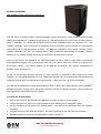
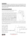
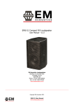
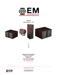
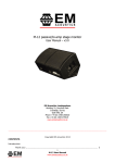
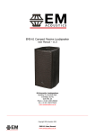
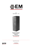
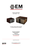
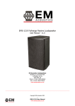
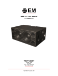
MSE-159/MSE-156 Fullrange Passive Loudspeakers
User Manual – v1.0
EM Acoustics Loudspeakers
Building 74, Dunsfold Park
Cranleigh, Surrey
GU6 8TB, UK
Phone +44 (0) 1483 266520
Fax +44 (0) 1483 275619
www.emacoustics.co.uk
_________________________________________________________________________________________
Copyright EM Acoustics 2012
1
MSE-159/MSE-156 User Manual
www.emacoustics.co.uk
CONTENTS
Introduction
Thank you ...……………………………………………………………………………………………………………………………. 3
Unpacking ……………………………………………………………………………………..……………………………………….. 3
Declaration of Conformity …………………….…………………………………………………………………………………… 3
Product Overview
MSE-159/MSE-156 passive two-way enclosures…………………………………………………………………….……… 4
System Set-up
Safety Considerations………………………………………………………………………………………………………………… 5
Cabling & Amplifier selection ……………………………………………………………………………………………………… 6
Protective DSP Settings ................................................................................................................. 7
Mounting & Rigging Options
Rigging Hardware & Accessories ………………………………………………………………………………………………… 8
Permanent Installations …………………………………………………………………………………………………………….. 8
Flying hardware Use........……………………………….…………………………………………………………………………. 9
Maintenance
MSE-159 Drive Unit Service ……………………………………………………………………………………………………….11
Warranty ……………………………………………………………………………………………………………………………………………. 12
Appendix A – Technical Specifications …………………………………………………………………………………………………… 13
2
MSE-159/MSE-156 User Manual
www.emacoustics.co.uk
INTRODUCTION
Thank you
Thank you for purchasing a product from the acclaimed EMS Series from EM Acoustics. The EMS Series products
have been carefully designed and rigorously tested to ensure years of flawless operation and unprecedented sonic
quality. Flexibility is the key factor with EMS products, and consequently they are at home within a wide variety of
applications from live and portable applications, through to cafes, bars, nightclubs, theatres and conference
centres.
Please ensure that you read this manual carefully before use, and that you keep it to hand should you need it for
further reference. Furthermore, should you have any difficulties please do not hesitate in contacting your EM
Acoustics dealer, or email [email protected] for further assistance.
Unpacking
Every EM Acoustics product is built to the highest standard and thoroughly tested before it leaves our factory.
After unpacking your loudspeaker, please inspect it carefully for any signs of transit damage. If such damage is
found, please notify the carrier at once to instigate a claim. It is suggested that you retain all packaging for future
re-shipment.
DECLARATION OF CONFORMITY
The products contained within this manual conform to the requirements of the EMC
Directive 89/336/EEC, amended by 92/31/EEC and to the requirements of the Low
Voltage Directive 73/23/EEC amended by 93/68/EEC.
Standards Applied:
EMC
Emission
EN55103-1:1996
Immunity
EN55103-2:1996
Electrical Safety
EN60065:1993
RECYCLING
This product and its packaging constitute the applicable product according to the WEEE directive.
Please ensure that at the end of the working life of this product, it is disposed of sensibly in
accordance with local and national recycling regulations. The packaging supplied with this product
is recyclable. Please retain all packaging, however if disposing of this packaging please ensure
that you comply with local recycling regulations. These products also all comply to the RoHS
Directive 2002/95/EC.
3
MSE-159/MSE-156 User Manual
www.emacoustics.co.uk
PRODUCT OVERVIEW
MSE-159/MSE-156 fullrange passive loudspeakers
The MSE-159 is a compact, versatile, passive loudspeaker product designed for a wide variety professional sound
reinforcement applications. It features a high-power 15” (381mm) neodymium LF drive unit in a reflex enclosure,
and a 4” diaphragm, 1.4” (36mm) exit neodymium high frequency compression drive unit coupled to a 90° x 60°
rotatable waveguide. These components are matched by an internal passive crossover network for unprecedented
sonic quality from a completely passive enclosure. The MSE-156 is identical in every respect, excluding that the
rotatable waveguide has a 60° x 40° coverage pattern. Sonic performance and character is incredibly consistent
between the two models, allowing easy mixing of the different products within a system.
Due to its discreet size and appearance, the MSE-159 and MSE-156 can be used in a wide variety of professional
audio applications ranging from corporate and theatre use up to medium scale front of house or in-fill/out-fill for
much larger systems.
The primary intention for the MSE-159 and MSE-156 were primary loudspeakers for
theatrical sound reinforcement.
As with all EM Acoustics full-range products, no active controller or programmed EQ is required for correct
operation. For demanding applications, a 50Hz, 24dB/octave high pass filter is recommended to increase drive unit
headroom however this is not essential for normal operation – please see page 7 for further information.
The MSE-159 and MSE-156 are supplied as standard in black or white, and is fitted with two Neutrik SpeakONTM
NLT4MP connectors. Custom colours and specific connectors can also be supplied if required – please contact your
local EM Acoustics representative for more details.
To rotate the HF waveguide:
1. Remove the front grille as described in the Maintenance section on Page 10 of this manual.
2. Using a 4mm Allen key, remove the eight countersunk bolts retaining the HF waveguide in place.
3. Lift the waveguide up and rotate to the desired position – the label on the waveguide shows the dispersion
orientation.
4. Reinstate the socket-head bolts and retighten. Avoid over-tightening as this may crack the waveguide.
5. Reinstate the grille as described in the Maintenance section on Page 11.
4
MSE-159/MSE-156 User Manual
www.emacoustics.co.uk
SYSTEM SET-UP
Safety Considerations
Loudspeaker systems are potentially dangerous objects if used incorrectly.
Please ensure that you read this
section fully, and contact EM Acoustics or your local dealer should you be in any doubt over correct operation
procedures.
Professional loudspeaker systems are capable of producing damage-inducing sound pressure levels, and hence
care should be taken when setting your system up, particularly when it comes to loudspeaker placement within a
venue. Damage to the ear can result from levels above 90dB under prolonged exposure.
Stand Mounting
The MSE-159 and MSE-156 can be mounted from a loudspeaker stand using the integral polemount adapter for a
standard 35mm loudspeaker stand. When mounting in this way, please consider the following:
Ensure your stand height is locked off and the tripod legs are positioned so as to be stable.
Check the weight loading of your stands before attempting to mount the loudspeaker.
Do not stack a second loudspeaker on top of the stand-mounted one.
Ensure cables are run so as to leave enough slack to enable neat wiring, and thus reduce the risk of the
speaker being pulled over. Loose cables should be covered or taped down wherever possible to reduce trip
hazards.
If stands are being used outdoors, it may be necessary to add ballast to the base of the stand to prevent it
toppling over.
When using poles on top of subwoofer systems, please observe similar precautions.
Ground Stacking
Ensure that the floor or stage surface can withstand the weight of the system.
Wherever possible, avoid high stacks and use ratchet straps to secure loudspeakers together. Please also
remember that vibrations from subwoofer systems can shake other loudspeakers out of place, which may
present a toppling hazard. The use of ratchet straps and non-slip material is recommended to prevent this.
Rigging and Suspension
There are a variety of different methods for suspending your MSE-19 enclosures – please see the detailed section
on Page 8 for further information.
WARNING: The overhead suspension of loudspeakers is a very serious issue with potentially lethal
consequences should anything go wrong.
Rigging should only be carried out by experienced
5
MSE-159/MSE-156 User Manual
www.emacoustics.co.uk
personnel following safe working practice. Should you be in any doubt whatsoever, please contact
your local dealer who will be able to refer you to a suitable rigging company.
Cabling and Amplifier Selection
The MSE-159 and MSE-156 are designed to be used with professional power amplifiers providing the following
power outputs:
MSE-159/MSE-156
1500W/channel into eight ohms
2 x MSE-159/MSE-156
3000W/channel into four ohms
A small power amplifier working too hard is more likely to damage a loudspeaker than a large power amplifier
working within its operating range!
It is good practice to use an amplifier equal to the program power rating of the loudspeaker – so as to retain
sufficient headroom and good dynamic range. Care should be taken during operation to avoid amplifier clipping,
and it is recommended that suitable limiters are applied in order to keep amplifier channels clear from clipping – as
this can cause serious damage to your loudspeakers. If in doubt, please contact your dealer who will be happy to
assist you in correct amplifier choice and setup.
Cabling
The MSE-159 and MSE-156 are supplied as standard with Neutrik SpeakONTM NLT4MP connectors, wired pin 1+/1-.
It is recommended that the resistance of your cable is less than one tenth of the nominal system impedance.
Given below are the recommended maximum cable lengths for different cross-sections and impedances.
Conductor Cross Sectional Area
Maximum Recommended Cable Length
4 ohms
8 ohms
16 ohms
2
1.0mm
11m
22m
44m
1.5mm2
17m
34m
68m
2
2.0mm
22m
44m
88m
2.5mm2
29m
58m
116m
2
4.0mm
44m
88m
176m
6.0mm2
66m
132m
264m
Pins 2+/2- on the SpeakONTM connectors are wired together to allow link-through with 4-core cables.
6
MSE-159/MSE-156 User Manual
www.emacoustics.co.uk
Protective DSP Settings
The MSE-159 and MSE-156 require no DSP program to function correctly.
However, excessive low frequency
information will cause the LF drive unit’s excursion to increase, which can result in damage to your loudspeaker.
The higher you raise the high pass filter on an MSE-159, the more headroom and overall sound pressure level
output there is available. For most medium-to-high level applications, we would recommend a minimum of a 50Hz
high pass filter with a 24dB/octave slope to sufficiently protect the loudspeaker. For higher SPL applications, we
would recommend raising this filter – we would stress that the higher the filter, the safer the loudspeaker will be.
If you are in any doubt over suitable settings for your MSE-159, please don’t hesitate to contact EM Acoustics or
your local dealer for support and advice.
7
MSE-159/MSE-156 User Manual
www.emacoustics.co.uk
MOUNTING & RIGGING OPTIONS
Rigging Hardware & Accessories
The MSE-159 and MSE-156 have three options for mounting and suspension, both for temporary use and
permanent fixed installation.
The MSE-159 and MSE-156 are fitted with bespoke flying plates top & bottom of the enclosure to enable
suspension in a variety of ways. Simple suspension is available using M10 forged shoulder eyebolts (minimum
thread length 20mm) in the M10 threaded holes in the flying plates. These M10 points can also be used as
secondary safety points with M10 eyebolts.
The most common method for suspension uses the keyhole cutouts in the top & bottom flying plates. Machined
bosses on the optional flying hardware mate with these keyhole plates, allowing extremely swift attachment of
flying hardware in a touring environment. ¼” ball-lock pins secure the optional flying hardware into the flying
plates.
The MSE-159 and MSE-156 also has an M8 threaded fixing on the rear for use as a pull-back point or for
attachment of a secondary safety point.
With any suspension method, a second anchor point should be used as a safety.
Under no circumstances should the mounting points of one enclosure be used to suspend another
enclosure below it.
EM Acoustics are in no way responsible for the failure of incorrectly rigged
systems. This information relates specifically to the rigging techniques for the MSE-159/MSE-156
enclosure only. If you are in any doubt about safe practices for rigging loudspeakers, please contact
your local EM Acoustics dealer who will be able to advise you.
Permanent Installations
Any installation (permanent or temporary) must be securely attached to the structure of the building using chain,
steel wire or web straps that are certified and load rated for the loudspeaker system. Consideration must be taken
when determining the loading on the structure to include loudspeakers and rigging hardware, and the appropriate
safety factor can then be decided upon.
If you are in any doubt whatsoever, please contact your EM
Acoustics dealer who will be able to refer you to an experienced rigging company. A reputable rigging organisation
should also be able to advise on legislation regarding safety factors for suspended systems of this type.
8
MSE-159/MSE-156 User Manual
www.emacoustics.co.uk
Safety Considerations
When utilising any suspension method, a secondary safety must be used. For any suspension method, fit an M8
eyebolt to any of the rigging points. A safety steel can then be attached to this and connected to your safety
point. If you are in any doubt whatsoever about how to safely suspend your loudspeakers, do not
hesitate to contact your EM Acoustics representative who will be able to refer you to a qualified
rigging company for advice.
Attachment of the FC-159v vertical flying cradle
The FC-159v vertical flying cradle is intended particularly for touring
purposes, hence the extremely quick attachment method.
To attach the cradle, first release the two ball-lock pins from the coffin
plate on the cradle. Position the cradle over the top or bottom of the
loudspeaker (it can be flown either way up) and insert the bosses on
the bottom of the cradle’s coffin-shaped plate into the keyholes on the
enclosure’s flying plate. Slide the cradle to the rear of the enclosure
until the two ¼” diameter locking-pin holes line up. Insert the two
ball-lock pins into the holes to lock the cradle in place. IMPORTANT:
DO NOT ATTEMPT TO LIFT THE LOUDSPEAKER WITHOUT
BOTH BALL-LOCK PINS IN PLACE. The point on the top of the
flying cradle can be used for permanent installations or to secure a
hook clamp. Ensure that an eyebolt is secured to the rear point on
the MSE-159/MSE-156 (M8 at the rear) or one of the top points (M10 on top or bottom) to use as a secondary
safety. To set the angle of the loudspeaker, there are standard clamping levers on each side as a primary system
however as a secondary, and to act as a repeatable method for flying, the holes and ball-lock pins allow quick and
easy angle setting in 5-degree increments.
As shown in the diagram
opposite, as you rotate the
inner yoke different holes
will be available to secure
with the pins.
Select the
desired angle, and lock in
place with the attached balllock pin.
To give further
explanation, Holes A-D are
used for down-tilt and holes
9
MSE-159/MSE-156 User Manual
www.emacoustics.co.uk
E-H are used for up-tilt. Hole A is used for 0-degree angle, and also for multiples of 20 degrees above this (20, 40,
60, 80 degree down-angle). Hole B is used for 10 degrees, and multiples of 20 degrees above this (10, 30, 50, 70,
90 degree down angle). Similarly, Hole C is used for 5 degrees and multiples of 20 degrees above this (5, 25, 45,
65, 85) and Hole D is used for 15 degrees and multiples of 20 degrees above (15, 35, 55, 75). Holes E-H apply in
a similar way for up-tilt.
Attachment of the VFA-159 variable flying bracket
To attach the bracket, first release the two ball-lock pins from
the base of the bracket. Position the bracket over the top or
bottom of the loudspeaker (it can be flown either way up) and
insert the bosses on the bottom of the bracket into the keyholes
on the enclosure’s flying plate. Slide the bracket to the rear of
the enclosure until the two ¼” diameter locking-pin holes line
up.
Insert the two ball-lock pins into the holes to lock the
bracket in place. IMPORTANT: DO NOT ATTEMPT TO LIFT
THE LOUDSPEAKER WITHOUT BOTH BALL-LOCK PINS
IN PLACE. Finally, attach a hook-clamp to the sliding mounting
point and secure the mounting point bolt through the main
section of the VFA-159 bracket.
The VFA-159 bracket works on the centre of gravity of the MSE-159.
The lone hole in the centre of the VFA
bracket will mean the MSE-159 enclosure will hang level. Moving the pickup point to the rear of the enclosure will
add down-tilt, and moving to the front of the enclosure will apply up-tilt. Each notch represents 5-degrees of
angle, so by taking the weight of the loudspeaker the angle can easily be changed. The VFA-159 will allow a
maximum of 25 degrees of up-tilt and 30 degrees of down-tilt. For more extreme down-tilt angles, select the
rearmost notch and use the M8 point on the rear of the enclosure as a pull-back.
Ensure that an eyebolt is secured to the rear point on the MSE-159/MSE-156 (M8 at the rear) or one of the top
points (M10 on top or bottom) to use as a secondary safety.
10
MSE-159/MSE-156 User Manual
www.emacoustics.co.uk
MAINTENANCE
Your EM Acoustics loudspeakers have been rigorously tested before they leave our factory, to ensure that they give
you a lifetime of flawless operation. Should any of your drive units fail and need replacing, please follow the
guidelines below.
MSE-159/MSE-156: Low Frequency Drive Unit
1. Using a 3mm Allen key, undo the six M4 machine screws top & bottom of the enclosure (3 each end). Gently
remove the grille from the front of the enclosure.
2. Using a 5mm Allen key, remove the two M6 socket-head bolts holding the central grille brace in place.
3. Using a 5mm Allen key, remove the eight M6 socket-head bolts holding the drive unit in place, and keep them
safe – ensuring you have collected both the shake-proof and flat washers for each bolt. Gently lift the drive
unit out of its locating hole – please take care as it is heavy! Carefully disconnect the cables from the drive
unit.
4. To reinstate the driver, simply reverse the above procedure. Please observe the correct polarity – red cable to
positive terminal, black cable to negative.
5. Reinstate the grille by gently placing it in place over the front of the loudspeaker. Replace the six M4 machine
screws to secure it in place.
MSE-159/MSE-156: High Frequency Drive Unit
1. Follow the procedure above to remove the front grille.
2. Using a 4mm Allen key, remove the eight M6 countersunk socket-head bolts holding the waveguide in place.
Gently disconnect the cables from the drive unit and remove the unit from the enclosure.
3. To reinstate the drive unit, gently reconnect the cables (white cable to positive terminal, yellow cable to
negative) and insert back into position. Note the waveguide orientation for correct dispersion. Replace the
four bolts and gently tighten.
4. Reinstate the grille by gently placing it in place over the front of the loudspeaker. Replace the six M4 machine
screws to secure it in place.
11
MSE-159/MSE-156 User Manual
www.emacoustics.co.uk
WARRANTY
Limited Warranty
This EM Acoustics loudspeaker product is warranted to the original end-user purchaser and all subsequent owners
for a period of three years from the original date of purchase.
Warranty Coverage
This warranty covers defects in materials and workmanship. It does not include:
Damage or failure caused by accident, misuse, neglect, abuse or modification by any person other than an
authorised EM Acoustics representative.
Damage or failure caused by operating the loudspeaker product contrary to the instructions contained within
this manual.
Damage caused during shipment.
Claims based on any misrepresentation by the seller.
Products which contain anything other than the original components (or EM Acoustics factory supplied spare
parts).
Products on which the serial number has been removed, altered or defaced.
Returning your EM Acoustics loudspeaker
Should your EM Acoustics loudspeaker develop a fault, please return it (freight prepaid) in its original packaging,
along with proof of purchase to your local dealer or to:
EM Acoustics (Returns Department), Building 74, Dunsfold Park, Cranleigh, Surrey, GU6 8TB, UK
including a description of the suspected fault. Serial numbers must be quoted in all correspondence relating to the
claim. EM Acoustics or its representatives are in no way liable for any loss or damage in transit, and hence it is
recommended that the sender insure the shipment. EM Acoustics will pay for return freight should the repair be
covered under warranty.
EM Acoustics’ liability is to the replacement or repair (at our discretion) of any defective components, and as such
are not liable for any incidental and consequential damages including (without limitation) injury to persons,
damage to property or loss of use.
This warranty is exclusive and no other warranty is expressed or implied. This warranty is also in
addition to – and in no way detracts from – your statutory rights as a consumer.
12
MSE-159/MSE-156 User Manual
www.emacoustics.co.uk
APPENDIX A – TECHNICAL SPECIFICATIONS
EM Acoustics operates a continuous process of research and development, and as such reserves the right to alter specifications without notice.
MSE-159/MSE-156
Enclosure Type:
2-way, reflex loaded
Dimensions (HxWxD, mm/ins):
707/27.8 x 440/17.3 x 450/17.7
Net Weight:
43kg
Frequency Response (+/- 3dB):
65Hz – 20KHz
Phase Response:
250Hz – 12KHz +/- 45°
Sensitivity:
98dB, 1W/1m
Dispersion:
90 x 60 rotatable (MSE-159)
60 x 40 rotatable (MSE-156)
Drive Units:
15” (305mm) LF cone drive unit
1.4” (36mm) exit neo HF compression drive unit
Power Handling:
750W RMS, 1500W Program
Maximum SPL:
130dB continuous, 136dB peak
Nominal Impedance:
8 ohms
Crossover:
internal passive
Connectors:
2 x Neutrik SpeakonTM NL4TMP
Enclosure:
15mm (5/8”) Finnish Birch plywood
Rigging/Suspension:
Keyhole quick-release fixings top & bottom
4 x M10 exposed thread flypoints top & bottom
1 x M8 exposed thread safety point.
Internal steel angle bracing
35mm polemount socket
Grille:
Perforated polyester coated steel backed with acoustic foam
Options:
Colours
Connectors
Spares & Accessories:
FC-159v vertical flying cradle
VFA-159 variable angle flying bracket
DU-1505 replacement LF drive unit
CDU-1402 replacement HF drive unit
RFG-159 replacement foam/grille
PX-159 passive crossover network (MSE-159)
PX-156 passive crossover network (MSE-156)
13
MSE-159/MSE-156 User Manual
www.emacoustics.co.uk