1
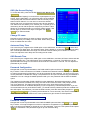
SCOUT 8
SCOUT 16
8 / 16 Port KVM Switch
Installation guide
Specifications
Part Numbers:
1014-108P
SCOUT 8 – 8 Port KVM Switch.
1014-116P
SCOUT 16 – 16 Port KVM Switch
Optional Cables:
2085-02P
SCOUT combi Cable 1.8m
2085-03P
SCOUT combi Cable 3.0m
2085-05P
SCOUT combi Cable 5.0m
2085-07P
SCOUT combi Cable 7.5m
2085-10P
SCOUT combi Cable 10.0 m
2141-01U
PS/2-USB Adaptor
Package Contents:
1014-108P
1 x SCOUT 8
1 x Power Adaptor
1 x Daisy Chain Cable 1.8m
1 x Rackmount Kit (19”)
Physical Properties
Height
1014-108P
4.45 cm
1014-116P
8.60 cm
1014-116P
1 x SCOUT 16
1 x Power Adaptor
1 x Daisy Chain Cable 1.8m
1 x Rackmount Kit (19”)
Width
41 cm
41 cm
Depth
16.5 cm
16.5 cm
Weight
2.2 kg
3.5 kg
Connections
Console Port
Computer Ports
Daisy Chain Port
Power
Power:
DC 9V 1A
1014-108P
1 x HD15 – VGA
1 x PS/2 – Keyboard
1 x PS/2 – Mouse
8 x HD15 – VGA
8 x PS/2 – Keyboard
8 x PS/2 – Mouse
1 x HD15 – VGA
1 x PS/2 – Keyboard
1 x PS/2 – Mouse
1 x DC Input
Max Resolution:
1920 x 1440
1014-116P
1 x HD15 – VGA
1 x PS/2 – Keyboard
1 x PS/2 – Mouse
16 x HD15 – VGA
16 x PS/2 – Keyboard
16 x PS/2 – Mouse
1 x HD15 – VGA
1 x PS/2 – Keyboard
1 x PS/2 – Mouse
1 x DC Input
Bandwidth:
200MHz
© Copyright 2005. All rights reserved.
Daxten, the Daxten logo, SCOUT and The Brains Behind KVM Switching and Sharing are trademarks of Daxten Industries. All
other trademarks acknowledged.
Revision 1.1
SCOUT 8 & SCOUT 16
Introduction
Thank you for purchasing the SCOUT 8 / SCOUT 16, KVM Switch. This product will ensure easy and
accurate control over your PCs through a single console. The SCOUT is compatible with PS/2 style
computers. It has keyboard and mouse emulation for error free boot-ups and supports a wide variety
of mice. The SCOUT supports high resolutions of up to 1920 x 1440 without any deterioration of the
image quality. Switching between PCs can be accomplished in three ways: through keyboard Hot Key
commands, by using the convenient front panel selection buttons or through the OSD (On-ScreenDisplay).
Product Features
¾
¾
¾
¾
¾
¾
¾
¾
¾
¾
¾
8 or 16 port SCOUT Switch with On-Screen-Display - OSD
PS/2 connectors for Keyboard and Mouse
15 pin VGA connector
Cascadable up to 256 Computers
19" Rack-mount-kit included
Switching by front-panel push buttons, OSD or hotkeys
LED indicators
Resolution up to1920 x 1440 @ 85 Hz
Comes with Auto-Scan mode for convenient automatic switching.
Front panel status LEDs give a clear indication of the active PC.
Optional PS/2 to USB adaptor for USB Computers (2141-01U)
Hardware Installation
Installation
1.
Before connecting your computers and console devices to the SCOUT switch, please ensure
that all devices are powered off. Connecting devices while powered on may lead to damage
to your computers or the SCOUT switch. Daxten cannot be held responsible for damage
caused by connecting devices that are powered.
2.
Connect your keyboard, monitor and mouse to the console connectors on the rear of your
SCOUT switch.
3.
Connect each computer system to the SCOUT Switch.
4.
Power on the SCOUT Switch by attaching the power adapter cord.
Daisy-chain Multiple SCOUT Switches
1.
2.
3.
4.
5.
6.
7.
Make sure your SCOUT Switch, your PCs and peripherals are all in powered-off state. If not,
turn the power off for the SCOUT Switch, PCs and peripherals.
Connect the shared keyboard, PS/2 mouse and monitor to the console connectors on the
rear of the master (first) SCOUT Switch.
Connect the power adapter cord to power on the master SCOUT Switch.
Use a daisy-chain cable to connect the daisy-chain port (labelled daisy-chain in) of the
master switch to the console port of the second switch. Then connect the power cord to
power on the second SCOUT Switch.
If you are cascading more SCOUT switches, just repeat step 4.
Connect each computer system (still in powered-off state) in turn with your Combi CPU
Cable. Then power on each computer.
After you have set up and powered up the daisy-chain connection of the SCOUT Switches,
you have to perform a first-time initialization for all the switches either by pressing and
holding down Button 1 on the master switch for at least 2 seconds, or using the hotkey
sequence: Scroll Lock Scroll Lock End for daisy-chain initialization.
Reset
The SCOUT Switch can be reset without disconnecting or powering down your computers either by
pressing down Button 1 on the front panel for 2 seconds, or with the hotkey sequence Scroll Lock
Scroll Lock End
Note: Each keystroke should be followed by its next keystroke within 2 seconds!
Note: After you have set up cascaded SCOUT Switches, and you want to initialize this
setup for the first time, you should perform the reset on the first (master) switch (that is,
the first bank) to initialize. Also remember to turn on all the other switches on the daisychain. The reason is that the first (master) switch will send message to the slave units. If
the slave units are not there to receive and respond to this reset message, system errors
will occur. If you want a reset later during your operation, you can do on the SCOUT’s
other than the master unit.
Keyboard Hot Key commands
To send Hot Key commands to the SCOUT switch, press and release the Scroll Lock Scroll Lock
within 2 seconds. Press a command key for the desired effect. The following commands are
supported:
First Key
Second Key
Scroll Lock
Command Key
2 digit bank number +
2 digit port number
Command Result
Switches to the desired PC
Scroll Lock
Scroll Lock
Scroll Lock
↑
Switch to previous PC
Scroll Lock
Scroll Lock
↓
Switch to next PC
Scroll Lock
Scroll Lock
Page Up
Next lower unit (bank)
Scroll Lock
Scroll Lock
Page Down
Next higher unit (bank)
Scroll Lock
Scroll Lock
B
Sound ON/OFF for Auto-Scan
Scroll Lock
Scroll Lock
S
Auto-Scan ON
any key
Scroll Lock
Scroll Lock
R
Stop Auto Scan
Refresh EEPROM
Scroll Lock
Scroll Lock
F
Find PC by Name
Scroll Lock
Scroll Lock
Space Bar
Displays OSD
Scroll Lock
Scroll Lock
End
Reset KVM
In Auto-Scan mode, the image shown on the monitor will automatically switch to the next computer.
After the last computer has been shown, the first computer will be shown again.
Note: In Auto Scan mode there is no mouse or keyboard control. Press any key to exit
the Auto-Scan mode. The SCOUT switch will stop at the last PC shown
Selection buttons
Pressing the individual PC buttons on the front of the SCOUT will switch the signal to the desired
computer.
OSD (On-Screen-Display)
To access the OSD, press the Hot Key Scroll Lock Scroll Lock
Space Bar.
OSD (On Screen Display) is a menu that is superimposed on your
screen. On the OSD Menu, you will have a listing of the available
units (banks) and channels for selection and the currently online
status of each channel. You can use it to control the SCOUT
Switch with more convenient and intuitive menu-driven operation.
The OSD menu also allows you to rename your computer (up to 9
characters), and to find the specific computer by its name. It also
allows you to password-protect your SCOUT Switch system. Use
the left, right, up, down cursor keys to navigate. Use Enter /
Insert key to select and edit.
Change PC name
Navigate to the PC Name you want to change, and then press
Enter or Insert key for editing a new PC name. When done, press
Enter to validate the new name.
Figure 1 – OSD Display
Autoscan Delay Time
Use cursor keys to navigate to the SCAN option on the OSD Menu, and then hit Enter to select and
edit the auto scan delay time. The Autoscan Delay Time is default to 10 seconds. The autoscan delay
time could be specified within the range of 5 seconds to 99 seconds by an increment of 1 second.
Users can adjust the scan delay time according to their needs.
OSD Remain Time
Use cursor keys to navigate to the OSD option on the OSD Menu, and then hit Enter to select and edit
the OSD Remain time. The OSD Remain Time is defaulted to 10 seconds. The OSD time can be
specified within the range of 5 seconds to 99 seconds in increments of 1 second. You can adjust this
parameter to your needs.
Password Configuration
Navigate with cursor keys downwards to the PWD CONFIG option and then hit Enter key or Insert
key to select. Follow the submenu to Enable or Disable the Password Protection. Every time you want
to change the password configuration, you will be prompted for the password. You have to type in the
correct password to validate the change. The password can be up to 8 characters long and defaults to
00000000. You can change the default password with your own password with the PWD CHANGE
option.
The Password Configuration (PWD CONFIG) function defaults to “No password protection”. When
password protection is enabled, then every time the SCOUT Switch is reset, it will prompt the next
user for a password. This feature will provide security to the local KVM console preventing
unauthorised access or accidental tempering of your computers by unauthorized persons. If you are
concerned about security of the KVM console, you should have the password protection enabled with
this OSD option. The next time you leave the KVM console, press the reset hotkey sequence: Scroll
Lock Scroll Lock End (or by pressing the last button for over 2 seconds). The SCOUT Switch will
reset and next user will be asked for the correct password to gain access to KVM operation.
Note: The Default password is 00000000
Password Change
Navigate with cursor keys downward to the PWD CHANGE option and then hit Enter key or Insert
key to select. A Prompt will appear on screen to request for old password. Type in the old password
and a new prompt will appear to request for your new password. Type in the new password and press
Enter for confirmation. The password length is up to 8 characters long.
Service Information
Technical Support
If you cannot determine the nature of a problem, please call Daxten and ask for Technical Support. If
possible, call from a phone located near the unit, as we may be able to solve your problem directly
over the phone. If we cannot solve your problem, and determine that the fault is in the unit, we will
issue a Return Material Authorisation (RMA) number that must appear on the outside of all returned
products. The unit should be double-packed in the original container, insured, and shipped to the
address given to you by our Technical Support representative. The Technical Support offices are
found on the back of this manual.
Limited Warranty
Daxten warrants to the end user that this product is and will be free from defects in materials and
workmanship for a period of 24 months from the date of purchase. If during the warranty period the
product should fail, the purchaser must promptly call Daxten for a RETURN MATERIALS
AUTHORIZATION (RMA) number. Make sure that the RMA number appears on the packing slip, proof
of purchase, AND ON THE OUTSIDE OF EACH SHIPPING CARTON. Unauthorized returns or collect
shipments will be refused.
Ship prepaid to the Daxten office (see back page) where you purchased your product. The above
limited warranty is voided by occurrence of any of the following events, upon which the product is
provided as is, with all faults, and with all disclaimers of warranty identified below:
1.
2.
3.
4.
5.
6.
7.
If non-Daxten approved power supply or cabling is attached to the product.
If defect or malfunction was caused by abuse, mishandling, unauthorized repair, or use other
than intended.
If unauthorized modifications were made to product.
If unreported damages occurred in any shipment of the product.
If damages were due to or caused by equipment or software not provided by Daxten.
If the product is used with non-grounded or incorrectly polarized AC power.
If the product is used in contradiction to any instruction provided by any User Guide or
Instruction Sheet provided to you or with the product.
EXCEPT AS SPECIFICALLY PROVIDED ABOVE AND TO THE MAXIMUM EXTENT ALLOWED BY
LAW, DAXTEN DISCLAIMS ALL WARRANTIES AND CONDITIONS WHETHER EXPRESS,
IMPLIED, OR STATUTORY AS TO ANY MATTER WHATSOEVER INCLUDING, WITHOUT
LIMITATION, TITLE, NON-INFRINGEMENT, CONDITION, MERCHANTABILITY OR FITNESS FOR
ANY PARTICULAR OR INTENDED PURPOSE.
EXCEPT AS EXPRESSLY PROVIDED ABOVE AND TO THE MAXIMUM EXTENT ALLOWED BY
LAW, DAXTEN SHALL NOT BE LIABLE FOR ANY SPECIAL, INDIRECT OR CONSEQUENTIAL
DAMAGES (INCLUDING WITHOUT LIMITATION, LOSS OF PROFIT, LOSS OF BUSINESS, LOSS
OF INFORMATION, FINANCIAL LOSS, PERSONAL INJURY, LOSS OF PRIVACY OR
NEGLIGENCE) WHICH MAY BE CAUSED BY OR RELATED TO, DIRECTLY OR INDIRECTLY, THE
USE OF A PRODUCT OR SERVICE, THE INABILITY TO USE A PRODUCT OR SERVICE,
INADEQUACY OF A PRODUCT OR SERVICE FOR ANY PURPOSE OR USE THEREOF OR BY
ANY DEFECT OR DEFICIENCY THEREIN EVEN IF DAXTEN OR AN AUTHORIZED DAXTEN
DEALER HAS BEEN ADVISED OF THE POSSIBILITY OF SUCH DAMAGES OR LOSSES.
Waste Electrical and Electronic Equipment (WEEE)
Within the European this symbol indicates that this product should not be disposed in
household waste. It should be deposited at an appropriate facility to enable recovery and
recycling. For information on how to recycle this product, please check with the reseller of the
product that replaces this product "Take Back" or the original seller of this product.
www.daxten.com
Ireland
Bay 21
Free Zone West
Shannon, Co. Clare
[email protected]
www.daxten.ie
Tel: +353 (0) 61 23 4000
Fax: +353 (0) 61 23 4099
USA
811 W. Evergreen Ave
Suite 302A
Chicago, IL 60622
[email protected]
www.daxten.us
Tel: +1 312 475 0795
Fax: +1 312 475 0797
United Kingdom
5 Manhattan Business Park
Westgate
London W5 1UP
[email protected]
www.daxten.co.uk
Tel: +44 (0) 20 8991 6200
Fax: +44 (0) 20 8991 6299
•
•
•
Österreich
Künstlergasse 11/4
A-1150 Wien
[email protected]
www.daxten.at
Tel: +43 (0)1 879 77 65
Fax: +43 (0)1 879 77 65 30
Deutschland
Salzufer 16, Geb. B
10587 Berlin
[email protected]
www.daxten.de
Tel: +49 (0) 30 8595 37-0
Fax: +49 (0) 30 8595 37-99
Schweiz
Seebahnstr. 231
8004 Zürich
[email protected]
www.daxten.ch
Tel: +41 (0) 43 243 32 11
Fax: +41 (0) 43 243 32 16
•
•
•
España
C/Florian Rey, 8
50002 Zaragoza
Sweden
[email protected]
www.daxten.se
[email protected]
www.daxten.com.es
Tel: +34 902 197 662
Fax: +34 976 201 633
Denmark
[email protected]
www.daxten.dk
France
B.P 04 - 77
Route de Cheptainville
91630 Marolles-en-Hurepoix
[email protected]
www.daxten.fr
Tel: +33 (0)1 64 56 09 33
Fax: +33 (0)1 69 14 88 34
•
•
•
•