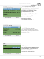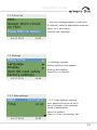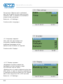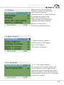
1
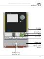
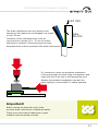
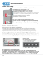
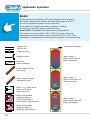
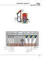
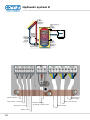
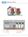
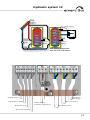
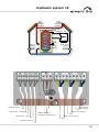
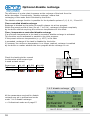
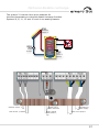
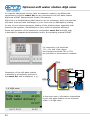
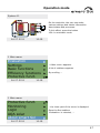
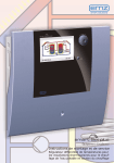
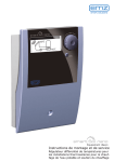
These Assembly and Operating Instructions are an integral part of the product.
> Read Assembly and Operating Instructions carefully before using the product.
> Keep them in a safe place during the product‘s service life.
Translation from the German original edition ©emz 2011 - Subject to modifications.
Table of Contents
Table of contents
Page
Important fundamental information
4
Symbols used
5
Description
6
Dimensions
7
Technical Data
8
Designation of the components
10
Operation of the controller
12
Display
13
Opening the terminal cover
14
Wall-mounting
15
Connection to power supply
16
Optional features
18
Hydraulic systems
20
Optional disable recharge
36
Optional soft water station AQA solar
40
Commissioning mode
41
Automatic mode
46
Operation mode
47
Malfunction
60
Replacement of fuse
66
Professional mode
67
Disassembly/Disposal
85
Warranty and liability
86
Copyright 87
Commissioning report
88
Error report
89
EC Declaration of conformity
90
Index
91
3
Important fundamental information
These instructions describe installation, commissioning, operation, repair
and disassembly of the differential temperature controller smart Sol for
solar thermal plants.
For operation of the entire plant, the technical documentation of all the
components used such as solar collectors, boiler, tank, pumps, mixers
and valves etc. must be complied with.
Danger!
Assembly, connection, commissioning, repair and disassembly of
the controller may only be performed by a qualified specialist!
The controller is handled by the operator of the entire solar
thermal plant, i. e. as a rule by technical non-experts.
Danger!
The controller by no means replaces the safety
components required under plant engineering aspects!
Make sure not to use the controller until you have thoroughly read and
understood these Assembly and Operating Instructions and the safety provisions.
Comply with all safety provisions and involve a specialist in case of doubt.
Important!
The fitter installing the controller must inform the plant operator about
operation, functioning and the method of action of the smart Sol!
Keep these Assembly and Operating Instructions and all reference
documents so that they are available if required.
When relocating or when selling the device, hand the documents over to your successor.
Danger!
The device in operation may only be made accessible to
adults disposing of appropriate knowledge and experience!
4
Symbols used
When handling the differential temperature controller smart Sol
and the entire plant, please make sure that the following safety provisions
in the Assembly and Operating Instructions are complied with!
Danger!
Immediate danger for assets, life and limb!
Important!
Important information compliance with which is essential!
Note!
Useful information regarding handling of the device and the plant!
5
Description
The differential temperature controller smart Sol is an independent electronic
controller for surface-mounting which is used for the control of solar thermal plants.
The controller is equipped with a robust three-part plastic housing
which can only be opened by means of tools (screw driver PH2).
Operation is effected by means of only two control elements;
indications appear against a backlit colour display.
Before connection of the electrical system, the controller
must be mounted firmly to a perpendicular, robust surface (wall).
For its own supply and the supply of the outputs, the controller must be connected
to an electrical energy supply system in accordance with the technical data.
Note!
The device must be connected to the power supply via an earth contact
plug or, in case of stationary electrical installation, via a disconnector
ensuring complete isolation according to the erection regulations!
Assembly, connection, commissioning, repair and disassembly
of the controller are only admissible in a specialist workshop.
To ensure correct operation, temperature sensors type Pt 1000
must be used - the sensor design does not affect function.
Each temperature sensor has two connectors which are equivalent,
i. e. interchangeable. Thus, polarity reversal is not an issue.
The sensor lines can be extended up to a length of 100 m, to
this effect, a cable cross section of 2 x 1.5 mm2 is recommended.
Important!
Make sure that only a dry or slightly moistened cloth is used for cleaning and servicing of the housing, the control elements and the display.
The surfaces must never get into contact with cleaning products
or solvents - mat, brittle or slightly dissolved plastic parts must
be replaced immediately!
A device with damaged housing must not be operated!
6
Dimensions
115 mm
46 mm
dmax 5mm/9mm
26 mm
57,5 mm
57,5 mm
173 mm
120 mm
5 mm
27 mm
7
Technical Data
Intended Use
The differential temperature controller may be used exclusively as controller for the control of solar thermal plants. It must be operated within the scope of all the specifications
described. Installation and set-up of the controller may only be performed by specialists.
The fitter must have read and understood the operating manual.
The fitter explains all the relevant functions to the operator.
For operation, it is essential that the housing is closed and free of damage.
Scope of supplies
1 Differential temperature controller smart Sol
1 Instruction manual
Differential temperature controller smart Sol
Type of mounting
Wall-mounting
Housing Plastics, in several parts
Type of protection IP 20
Dimensions Width x Height x Depth [mm] 115 x 173 x 46
Weight [g] Basic version 370
Storage/operating temperature [°C] 0-40, non-condensation
Handling
via rotary encoder and pushbuttons
Display TFT colour display 47 x 35 mm, backlit
Connection to power supply
Design
3 spring-type terminals PE, N and L
Service voltage [VAC] 230 ±10%
Line frequency [Hz] 50 ±1%
Auxiliary consumption typ. [W]
1,74
Power consumption max. [W]
3.5
Fuse
Micro fuse, type 5 x 20 mm, T2A
Rated pulse voltage [V]
2500
8
Technical Data
Interfaces TS 1 / TS 2 / TS 3 / TS 4
Design
2 spring-type terminals each
Assignment as inputs
Admissible temperature probe Temperature sensor Pt 1000
Optional assignment of
TS3 / TS4 to the impeller sensor
DFZ 1-100 pulses/litre
Optional assignment as
output on TS 4
PWM signal 100Hz...2kHz or
analogue output 0...10V, max. 10mA
Triac outputs RO 1 / RO 2
Design
3 spring-type terminals each, PE, N and L
Output voltage [VAC] 230 ±10%
Output power max.
per output [VA] 200
Output current max.
per output [A] 1
Switching output REL: Floating change-over contact
Design
3 spring-type terminals
Switching voltage max. [V] 253
Switching capacity max. [VA] 800
Switching current max. [A] 4
Max. cross sections to be connected
Cable end sleeve:
0.25 to 0.75 mm2
Single-wire 0.50 to 1.50 mm2
Fine-wired 0.75 to 1.50 mm2
9
Designation of the components
Display
esc button
Rotary encoder
with OK button
Housing
cover
Terminal
cover
Screw fastening
of terminal cover
10
Designation of the components
Housing
base
Spare fuse
Fuse
Terminals
Break-out
segments
Strain relief
device
Drillhole for
securing bolt
11
Operation of the controller
The entire set-up and operation of the differential temperature controller
smart Sol is effected via only two control elements on the device front.
All settings and interrogations are effected via the rotary encoder.
To find a required menu item, turn the rotary encoder to ›scroll‹
through the menu - the selectable option appears on a coloured
background on the display.
To confirm the selected menu item, press the rotary encoder.
An appropriate submenu is called up, or selection is activated.
Press the esc button to make the menu return by one level from any subitem.
If no input is made within the preset time (30-255 s),
the controller returns automatically to the initial level.
12
Display
For indication of the operating mode and for communication in case of set-up,
malfunction, modification and evaluation, the differential temperature controller
smart Sol is equipped with a coloured full graphics display which is permanently backlit.
The display is active as long as there is supply voltage on the controller.
After a preset time (30 - 255 s), backlighting is dimmed to 10%.
System 11
Active system
with current
temperatures
Date and time
Display elements; example: information screen
Number and name of menu
Professional mode
Manual mode
Message
1.3.2 Tube collector
n solar 1
t solar 2
n solar 2
t start
t end
04. 07. 2011
100%
20s
30%
6:00
7:00
10:35
Selection menu
Activatable
menu item
Date and time
Display elements; example: communication screen
13
Opening the terminal cover
Danger!
Mortal danger due to electrocution! Whenever work is performed on the
open terminal cover, all poles of the power supply must be
disconnected reliably and protected against being switched on again!
1
2
Release the lock screw.
Swing terminal cover
forward ...
3
... push it upwards ...
4
... and remove it.
Store the terminal cover
carefully and protect
it against damage!
To close the terminal cover,
reverse the opening procedure.
14
Wall-mounting
Important!
The device corresponds to protection type IP 20 - make sure the
appropriate prerequisites exist on the envisaged place of installation.
Do not use the housing base as drill template.
A device with damaged housing must not be operated!
1
2
Fasten the top securing bolt so
that a space of 2 to 3 mm is
created between the wall and
the screw head.
Move the device so that the
upper fastening port is located
above the screw head ...
3
... and push it downwards.
4
Fasten the lower securing bolt.
If necessary, use dowel
pins for wall-mounting!
15
Connection to power supply
Danger!
Mortal danger due to electrocution! Whenever work is performed
on the open terminal cover, all poles of the power supply must be
disconnected reliably and protected against being switched on again!
The differential temperature controller smart Sol is connected to the
power supply via three groups of spring-type terminals which are
visible once the terminal cover is opened.
To introduce the cables, release the three screws on the strain relief device;
if necessary, remove the strain relief device.
In case of flush mounting of the cables, the break-out segments in the housing
base can be removed carefully and the cables routed through these ports.
The central terminal block is the interface to a floating change-over
contact - here, it may be necessary to route electrical resistors into the
spring-type terminals and to connect part of the cables via luster terminals.
The spring-type terminals for the power supply, RO1, RO2 and REL, and for TS1,
TS2, TS3 and TS4 can accommodate solid wires up to a cross section of 1.5 mm2.
Appropriate stranded wires must be preassembled with cable end sleeves.
For the strain relief device function, TS1 to TS4 and REL require
cable cross sections of at least 5mm, for Power, RO1, RO2 at least 7mm.
Terminal block
TS1-TS4
Screw connection
strain relief device
16
Terminal block
REL
Resistor
Terminal block
RO2/RO1/Power
Luster terminal
Strain relief
device
Connection to power supply
9-10 mm
The strain relief device can only ensure solid
clamping if the cables are not stripped to a length
of over 35 mm.
Insulation of the individual wires must be
removed over a length of 9 - 10 mm to ensure
safe electric contact in the spring-type terminal.
max.
35 mm
Stranded wires must be provided with cable end sleeves!
For connection, press the actuation pushbutton
of the spring-type terminal using a screwdriver and
insert the wire to its stop in the appropriate port.
Release the actuation pushbutton and pull the
cable slightly to ensure that it is safely clamped.
Important!
Before closing the terminal cover, make
sure the strain relief device is tightened safely.
Check once more that all cables are in good
condition and connected correctly.
17
Optional features
Optional micro SD card:
The solar controller features the following data interfaces:
The recesses in the left-hand side of the
housing base accommodate an USB connector
and a slot for a data medium (micro SD card).
These interfaces can be used e. g. to read error messages or
saved data or to transfer software updates to the controller.
Access to the data on the micro SD card
is possible via the USB connector.
Only the SD cards authorized by emz may be used.
The micro SD card is detected by the controller automatically.
Before removing the micro SD card from the controller, the item
›Remove SD card safely‹ must be selected under ›1.2 Settings‹.
Optional volumetric flow sensor:
Measurement of solar radiation (heat quantity):
The solar yield is calculated from the flow rate and the differential temperature.
The differential temperature is the difference in the temperature of the collector
sensor and the solar circuit return line sensor. There are various technical options:
a) Use of a vortex volumetric flow sensor with 2 analog signals for flow rate and
temperature. The vortex sensor can be inserted directly at the plug connector provided
behind the TS3/4 terminals. All plant layouts permit solar radiation. When a vortex
sensor is connected to plug UI1/UI2, the cover plate at the housing must be broken out.
Plug connector for vortex
sensor behind the
terminals
TS3/TS4.
Pin assignment
Plug connector for vortex sensor:
1 = UI1 = Temperature sensor
2 = UI2 = Flow rate sensor
4
3
2
1
+5V
GND
UI2
UI1
b) Impeller sensor (incrementation input)
An impeller sensor can be connected to TS3 or TS4 and must be adjusted during
installation. The temperature sensor for the solar return line is connected to TS3 or TS4
and must then be set in the menu 1.1.4 Heat quantities. Solar radiation measurement
using an impeller sensor is possible for plant layouts 1, 2, 3, 4, 5, 7, 10, 12 and 14.
18
Optional features
Optional high-efficiency pump:
A high-efficiency pump can be connected via RO1 or RO2.
The appropriate control signal is issued at TS4.
Thus, TS4 is no longer available as input.
The control signal may be an analog voltage 0 - 10V or a PWM signal.
TS4: PWM-control signal
for the high-efficiency
pump
RO1 or RO2:
230V supply of the
high-efficiency pump
Left-hand terminal: GND
Right-hand terminal:Signal
For further details, please refer to the pump specification.
For definition and settings, the professional mode under 1.1.4 has been provided.
Connection of a switching valve to RO1/RO2
Connection diagram for a switching valve to RO2:
USV
blue
black
brown
L
Additional options:
• Option ›Disable recharge NLU‹: Description as of page 36.
• Option ›Soft water station AQA solar‹: Description on page 40.
• Option ›Power reserve‹:
This option can be used to buffer the time up to 8 hours in case of power failure.
• Option ›acoustic signal transmitter‹: The signal transmitter issues an acoustic
signal once an error has occurred. This can aso be deactivated in the menu.
19
Hydraulic systems
Note!
Define structure and design of the plant already when planning
the entire solar thermal system and align the design with the
one of the hydraulic systems of the controller!
If you want to complete an existing system or replace
the existing controller, please make sure that
smart Sol is compatible with the existing configuration!
The sensors are connected to TS1 to TS4, the order not being
significant; pumps and valves are connected to RO1 / RO2 - The
interfaces are assigned to the functions in question on commissioning.
Supply line
Return line
Temperature probes
Heating pump
Solenoid valve
Hydraulic
heat exchanger
Warm water /
buffer tank without
heat exchanger
Solar collector panel
Main yield
Solar collector panel
Secondary yield
Warm water /
buffer tank with one
heat exchanger
Boiler, e. g. using fossil
fuels/ solid fuels/
heat pump etc.
Boiler with disable
recharge feature
time-/temperaturecontrolled, in combination
Boiler with disable
recharge feature,
efficiency optimization
20
Warm water /
buffer tank with two
heat exchangers
Hydraulic system 1
TS1
Collector
sensor 1
RO1
Solar
circuit
pump 1
Tank 1
T1
TS2
Tank
sensor 1,
bottom
Collector sensor 1
Tank sensor 1, bottom
Connection to
power supply
Solar circuit pump 1
21
Hydraulic system 2
TS1
Collector
sensor 1
Tank sensor 1,
top
TS3
RO1
Solar
circuit
pump 1
Tank 1
T1
TS2
Tank
sensor 1,
bottom
Collector sensor 1
Connection to
power supply
Tank sensor 1, bottom
Tank sensor 1, top
22
Solar circuit pump 1
Disable recharge
according to page 36-39
Hydraulic system 3
TS1 Collector sensor 1
RO2 Charging area valve
sensor 1,
TS3 Tank
top
RO1
Solar
circuit
pump 1
Tank 1
T1
TS2
Tank
sensor 1,
bottom
Collector sensor 1
Tank sensor 1, bottom
Tank sensor 1, top
Connection to
power supply
Solar circuit pump 1
Charging area valve
23
Hydraulic system 4
TS1
Collector
sensor 1
sensor 1,
TS3 Tank
top
RO1
Solar
circuit
pump 1
Tank 1
T1
TS2
RO2
Charging
area valve
Tank
sensor 1,
bottom
Collector sensor 1
Tank sensor 1, bottom
Tank sensor 1, top
24
Connection to
power supply
Solar circuit pump 1
Charging area valve
Hydraulic system 5
TS1 Collector
sensor 1
RO1
Solar
circuit
pump 1
RO2
Heat
exchanger
pump
Collector sensor 1
Tank sensor 1, bottom
Heat exchanger sensor
Heat
exchanger
sensor
TS3
Tank 1 1
Speicher
T1
SP1
TS2
Tank
sensor 1,
bottom
Connection to
power supply
Solar circuit pump 1
Heat exchanger pump
25
Hydraulic system 6
TS1 Collector
sensor 1
Tank sensor 1,
top
RO1
Solar
circuit
pump 1
RO2
TS3
Heat
exchanger
sensor
TS4
Tank 1 1
Speicher
T1
SP1
Heat
exchanger
pump
Tank
sensor 1,
bottom
Collector sensor 1
Connection to
power supply
Tank sensor 1, bottom
Tank sensor 1, top
Heat exchanger sensor
26
TS2
Solar circuit pump 1
Disable recharge
according to page 36-39
Heat exchanger pump
Hydraulic system 7
TS1
Collector
sensor 1
Bypass
sensor
RO1
TS3
Solar
circuit
pump 1
Tank 1
T1
TS2
RO2
Bypass valve
Tank
sensor 1,
bottom
Collector sensor 1
Tank sensor 1, bottom
Bypass valve
Connection to
power supply
Solar circuit pump 1
Bypass sensor
27
Hydraulic system 8
TS1
Collector
sensor 1
Tank sensor 1,
top
TS3
Bypass
sensor
RO1
TS4
Solar
circuit
pump 1
Tank 1
T1
TS2
RO2
Bypass valve
Tank
sensor 1,
bottom
Collector sensor 1
Connection to
power supply
Tank sensor 1, bottom
Tank sensor 1, top
Bypass valve
28
Solar circuit pump 1
Disable recharge
according to page 36-39
Bypass sensor
Hydraulic system 9
TS1
Collector
sensor 1
Tank sensor 1,
top
TS3
Transfer
pump
RO1
Solar
circuit
pump 1
Tank 1
T1
RO2
TS2
Tank
sensor 1,
bottom
Tank 2
T2
TS4
Tank
sensor 2,
bottom
Collector sensor 1
Tank sensor 1, bottom
Tank sensor 1, top
Connection to
power supply
Solar circuit pump 1
Transfer pump
Tank sensor 2, bottom
29
Hydraulic system 10
TS1
Collector
sensor 1
Tank 1
RO1
Solar circuit
pump 1
Solar circuit
pump 2
RO2
T1
TS2
Tank
sensor 1,
bottom
Tank 2
T2
TS3
Tank
sensor 2,
bottom
Note: Priority charging has
been set to T2 in the factory.
Collector sensor 1
Tank sensor 1, bottom
Tank sensor 2, bottom
30
Connection to
power supply
Solar circuit pump 1
Solar circuit pump 2
Hydraulic system 11
TS1
Collector
sensor 1
sensor 2,
TS3 Tank
top
Tank 1
RO1
Solar circuit
pump 1
Solar circuit
pump 2
RO2
T1
Tank 2
TS2
T2
Tank
sensor 1,
bottom
TS4
Tank
sensor 2,
bottom
Note: Priority charging has
been set to T2 in the factory.
Collector sensor 1
Connection to
power supply
Tank sensor 1, bottom
Tank sensor 2, top
Solar circuit pump 1
Disable recharge
according to page 36-39
Solar circuit pump 2
Tank sensor 2, bottom
31
Hydraulic system 12
TS1
Collector
sensor 1
Speicher
Tank 1 1
RO1
SP1
T1
Solar circuit
pump 1
RO2
Tank switching valve
TS2
Tank
sensor 1,
bottom
Speicher
Tank 2 2
SP2
T2
TS3
Tank
sensor 2,
bottom
Note: Priority charging has
been set to T2 in the factory.
Collector sensor 1
Tank sensor 1, bottom
Tank sensor 2, bottom
32
Connection to
power supply
Solar circuit pump 1
Tank switching valve
Hydraulic system 13
TS1
Collector
sensor 1
sensor 2,
TS3 Tank
top
Speicher
Tank 1 1
RO1
SP1
T1
Speicher
Tank 2 2
TS2
SP2
T2
Tank
sensor 1,
bottom
Solar circuit
pump 1
RO2
Tank switching valve
TS4
Tank
sensor 2,
bottom
Note: Priority charging has
been set to T2 in the factory.
Collector sensor 1
Connection to
power supply
Tank sensor 1, bottom
Tank sensor 2, top
Solar circuit pump 1
Disable recharge
according to page 36-39
Tank switching valve
Tank sensor 2, bottom
33
Hydraulic system 14
TS1
Collector
sensor 1
Tank 1
T1
Solar circuit
pump 1
RO1
TS3
Collector
sensor 2
TS2
Tank
sensor 1,
bottom
Solar circuit
pump 2
RO2
Collector sensor 1
Tank sensor 1, bottom
Collector sensor 2
34
Connection to
power supply
Solar circuit pump 1
Solar circuit pump 2
Hydraulic system 15
TS1
Collector
sensor 1
TS4
Collector
sensor 2
TS3 Tank
sensor 1, top
Tank 1
T1
Solar circuit
pump 1
RO1
TS2
Tank
sensor 1,
bottom
Solar circuit
pump 2
RO2
Collector sensor 1
Connection to
power supply
Tank sensor 1, bottom
Tank sensor 1, top
Solar circuit pump 1
Disable recharge
according to page 36-39
Solar circuit pump 2
Collector sensor 2
35
Optional disable recharge
The efficiency of a solar plant increases as the recharge of the tank from the
boiler decreases. Consequently, "disable recharge" means that
recharging of the water tank is blocked by the boiler.
The disable recharge function is possible for the hydraulic systems 2, 6, 8, 11, 13 and 15.
Time-controlled disable recharge
Recharge is blocked by the boiler for specific phases via a time program.
Within the preset period of time (for ex. 7 to 19 h), recharge is blocked completely
by the boiler without requiring the minimum temperature to this effect.
Time-/temperature-controlled disable recharge
If a minimum temperature in the tank is exceeded, disable recharge is activated.
This function can be activated in parallel to the time program.
If the preset minimum temperature (e. g. 45°C) in the tank
is exceeded, recharge of the tank is disabled by the boiler.
If, however, the minimum temperature is no longer reached, recharge is enabled
by the boiler no matter whether the time program blocks recharge or not.
Check the heating boiler manual
to determine which sensor type
is used as tank sensor!
Sensor type
Pt 100
Pt 500
Pt 1000
R Terminal 14
130 Ω
620 Ω
1.3 kΩ
Colour code
Boiler
Tank sensor,
top
R (T=70°C)
1.4.3 disable recharge
All the parameters required for disable
recharge are set in professional mode
under ›1.4.3 disable recharge‹.
=> Professional mode as of page 67.
Activ. time progr.
Start
00:00
End
00:00
Activation T min.
T min. tank
45.0°C
04. 07. 2011
36
10:39
Optional disable recharge
The system 2 is shown here as an example for
the time/temperature controlled disable recharge function.
Systems 6, 8, 11, 13 and 15 work in an analog manner.
TS1
Collector
sensor 1
RO1
Solar
circuit
pump 1
Tank 1
T1
TS2
Tank
sensor 1,
bottom
Collector sensor 1
Tank sensor 1, bottom
Sensor line to
boiler controller
Boiler original
tank sensor 1,
top
Connection to
power supply
Solar circuit pump 1
37
Optional disable recharge
Efficiency-optimized disable recharge
For this disable recharge version, two sensors must
be mounted in the position of the upper tank sensor:
1.: the original boiler sensor of the heating plant.
2.: a Pt 1000 which is connected to TS3 of the smart Sol.
Now, a required recharge is optimized via algorithms which take account
of various factors such as the energy input and the heat requirements.
Check the heating boiler manual
to determine which sensor type
is used as tank sensor!
Sensor type
Pt 100
Pt 500
Pt 1000
R Terminal 14
130 Ω
620 Ω
1.3 kΩ
Colour code
Boiler
Tank sensor,
top
R (T=70°C)
1.4.3 disable recharge
All the parameters required for disable
recharge are set in professional mode
under ›1.4.3 disable recharge‹.
=> Professional mode as of page 67.
Activ. time progr.
Start
00:00
End
00:00
Activation T min.
T min. tank
45.0°C
04. 07. 2011
38
10:39
Optional disable recharge
The system 2 is shown here as an example for
the efficiency-optimized disable recharge function.
Systems 6, 8, 11, 13 and 15 work in an analog manner.
TS1
Collector
sensor 1
Tank sensor
1, top
TS3
RO1
Solar
circuit
pump 1
Tank 1
T1
TS2
Tank
sensor 1,
bottom
Collector sensor 1
Tank sensor 1, bottom
Tank sensor 1, top
Sensor line to
boiler controller
Boiler original
tank sensor 1,
top
Connection to
power supply
Solar circuit pump 1
39
Optional soft water station AQA solar
In a specific equipment version (with an extension module), the differential
temperature controller smart Sol can be connected to the soft water station
AQA solar of BWT Wassertechnik GmbH, Schriesheim.
AQA solar is a decalcification plant based on an ion exchanger, which ensures that
the water lines and heat exchangers in your home are not damaged by scaling.
In case of very intense temporary heating of the drinking water, especially with
thermal solar systems, decalcification is very useful to maintain efficiency.
Setup and operation of the equipment combination smart Sol and AQA solar
is described in separate documentation and/or the operating manual of BWT.
For connection, the terminals
›Tx‹, ›Rx‹ and ›Gnd‹ above
the interface terminals TS1 to TS4
are provided on the extension modules.
TS1
TS3
Integration of the soft water station
is possible in all hydraulic systems of
the smart Sol, and is displayed, e. g.:
RO1
TS2
1.8 AQA solar
Soft water
421l/h
Flow rate
Soft water delivery
317m3
04. 07. 2011
40
10:30
In the main menu, information transmitted
by the soft water station can be retrieved
under ›1.8 AQA solar‹.
Commissioning mode
Important!
For commissioning, the controller must be assembled
correctly, all inputs and outputs must be connected
and ready for operation, the strain relief device must
be screw-fastened and the terminal cover closed!
This is an explanation in terms of an example of commissioning of the
differential temperature controller smart Sol; details vary along with
the hydraulic configuration and the software version.
Commissioning is communicated in plain text; the user must make a
selection, acknowledge and - if applicable - jump to the next menu item.
The differential temperature controller smart Sol accompanies you during the
entire configuration and interrogates everything it must know for optimum operation.
Now, the power supply of the controller must be switched on, or the earth contact
plug of the supply cable inserted in a plugbox - the display screen appears.
0.1 Language
Deutsch
English
Français
Italiano
›0.1 Language‹ appears after
a short booting sequence.
Various languages are available
in this version of the smart Sol.
Next
04. 07. 2011
09:12
0.2 Time/Date
Time
Date
04. 07. 2011
Activate the required version and
acknowledge by pressing ›Next‹.
›0.2 Time/date‹ appears.
09:51
04.07.2011
Next
09:12
Press ›OK‹ - the hour is highlighted in colour.
Turn the rotary encoder until the
correct figure appears, and
acknowledge via the ›OK‹ button.
The controller accepts the value
and jumps to the minute setting.
In this way, all values for time and date
can be entered, and acknowledged by ›Next‹.
41
Commissioning mode
0.3 Inputs
›0.3 Inputs‹ appears.
TS1
Select and activate the input interfaces
TS1 to TS4 used and assign the selected
function to them by scrolling.
TS2
Once all inputs have been assigned correctly,
acknowledge by pressing ›Continue‹.
TS3
04. 07. 2011
--Coll--1
------09:12
Important!
At the interface TS4, an impeller sensor
can be selected as flowmeter via ›Impeller‹.
›0.4 Volumetric flow‹ appears.
If TS4 has already been assigned to
›Impeller‹, ›Impeller‹ will appear here in
terms of sensor system. The number of
pulses per litre still has to be selected.
If the assignment of TS4 is different or
if no assignment has been made, only
a vortex can be selected here.
To this effect, the installed vortex volumetric
flow sensor still has to be defined.
Acknowledge by pressing ›Next‹.
0.4 Volumetric flow
Sensor system
Impeller
Pulses/litre
14Imp/l
Next
04. 07. 2011
Important!
A high-efficiency pump can be connected to TS4.
The WILO ST 25/7 PWM is preassigned.
42
09:13
Commissioning mode
0.5 Outputs
RO1
RO2
REL
------Next
04. 07. 2011
›0.5 Outputs‹ appears.
Select and activate the output interfaces
RO1, RO2, REL used and assign them to
the selected function by scrolling.
Once all outputs have
been assigned correctly,
acknowledge by pressing ›Next‹.
09:13
System 2/3
Now, the controller offers the hydraulic
systems which are possible due to the
assigned inputs and the selected outputs.
By turning the rotary encoder, the
required system can be selected
(here system 2 of 3 possible ones)
and acknowledged via the button ›OK‹.
04. 07. 2011
09:13
Note!
Here, access to all plant layouts is possible for testing purposes
via the option ›Show all‹. However, for correct operation, one of
the plant layouts suggested by the controller must be selected.
43
Commissioning mode
0.7 Checklist
›0.7 Checklist‹ appears.
Test outputs
Holiday function
Here, the output test is offered first - call
up the test by pressing the button ›OK‹.
04. 07. 2011
›0.8 Output test‹ appears.
Here, the outputs can be activated manually
via the ›OK‹ button to test the function of
the activated output or of the connected unit.
If not all pumps and valves are working
properly, the plant elements in question and
the cabling must be verified and repaired.
Acknowledge by pressing ›Next‹.
›0.7 Checklist‹ reappears.
As the plant, when not in use, is only
supplied with heat, but no heat is withdrawn,
it may be subject to overheating and damage.
44
09:13
0.8 Output test
RO1
RO2
REL
04. 07. 2011
Next
09:13
0.7 Checklist
Monitoring
Holiday function
Thus, a ›holiday function‹ was
programmed which minimizes heat input.
Here, the holiday function can be set call up by pressing the ›OK‹ button.
Next
04. 07. 2011
Next
09:14
Commissioning mode
0.7.2 Holiday function
Tank recooling
Soft charge
120.0°C
T-ON
100.0°C
T-OFF
Next
04. 07. 2011
09:14
Various options can be selected
for the holiday function.
At lower ambient temperatures
(e. g. at night), tank recooling tries
to dissipate heat via the collectors.
The soft charge circuit is designed so that the
heat input into the tank is as low as possible.
The appropriate switch-ON and OFF
temperatures must be varied as required.
Acknowledge by pressing ›Next‹.
0.9 End
You have completed
commissioning!
›0.7 Checklist‹ reappears.
Acknowledge by pressing ›Next‹.
›0.9 End‹ appears.
Next
04. 07. 2011
By ›Next‹, the controller
changes over to ›Automatic mode‹.
09:15
System 11
Commissioning is complete.
As of this point, the smart Sol controls
the solar thermal plant automatically.
04. 07. 2011
09:16
45
Automatic mode
In automatic mode, the screen
displays the date, the time and
the active hydraulic system.
System 11
The current temperature is displayed
for each temperature sensor.
The pump activity is displayed
on the display as animation.
There is no need for intervention
by the fitter or operator.
04. 07. 2011
Note!
Check the display screen of the smart Sol on a regular
basis to be able to eliminate any malfunctions promptly!
46
09:17
Operation mode
System 11
On the controller, the user can make
various settings and obtain information
about states and processes.
To this effect, press the button
›OK‹ in automatic mode.
04. 07. 2011
10:19
1 Main menu
Evaluation
Settings
Basic functions
Efficiency functions
Protective funct.
04. 07. 2011
›1 Main menu‹ appears.
A list of subitems appears
By scrolling ...
10:19
1 Main menu
Protective funct.
Monitoring
Login
AQA solar
about smart Sol
04. 07. 2011
...the lower part of the menu is displayed.
Once the first subitem
›Evaluation‹ is selected, ...
10:19
47
Operation mode
1.1 Evaluation
...›1.1 Evaluation‹ appears.
Another selection level appears.
Once the first subitem
›Measured values‹ is selected, ...
Measured values
Service hours
CO2 savings
Heat quantities
Error list
04. 07. 2011
10:20
1.1.1 Measured values
...›1.1.1 Measured values‹ appears.
Here, the temperatures and dates
concerning the controller are displayed.
By scrolling ...
Coll 1
Tank 1 bottom
Tank 2 bottom
Tank 2 top
Flow temp.
04. 07. 2011
78.2°C
47.0°C
42.1°C
61.4°C
68.7°C
10:20
1.1.1 Measured values
...the lower part of the menu
(if available) is displayed.
Return to ›1.1 Evaluation‹.
Once the second subitem
›Service hours‹ is selected, ...
68.7°C
Flow temp.
1.3l/min
Flow rate
34%
Solar pump 1
Tank ch.-over v 1 OFF
Disable recharge OFF
04. 07. 2011
48
10:20
Operation mode
...›1.1.2 Service hours‹ appears.
1.1.2 Service hours
112h
Solar pump 1
Tank ch.-over v 1 94h
Disable recharge 361h
Reset
04. 07. 2011
10:21
The operating time of the activated plant
components is displayed in hours.
By actuating the menu item ›Reset‹,
all counters are reset to zero.
The values are saved once per day, so
that one day max. is "lost" in case of
failure of the power supply.
Return to ›1.1 Evaluation‹.
Once the third subitem
›CO2 savings‹ is selected, ...
1.1.3 CO2 savings
Activation
Savings
Reset
Fuel
04. 07. 2011
447 kg
Natural gas
...›1.1.3 CO2 savings‹ appears.
Here, assessment of the saved carbon
dioxide can be activated, read and reset.
By selecting ›Fuel‹...
10:21
Edit
Fuel
Natural gas
Restore last value
Factory settings
...›Edit‹ appears.
Here, the fuel types natural gas or fuel oil
can be selected for a calculation of CO2.
Return to ›1.1 Evaluation‹.
Continue with ›Heat quantities‹.
04. 07. 2011
10:22
49
Operation mode
1.1.4 Heat quantities
›1.1.4 Heat quantities‹ appears.
Activation starts a counter which
determines the heat yield of the solar plant.
Press ›Reset‹ to reset the counter to 0.
Activation
Week
Diagram
Heat quantity 108 kWh
Reset
04. 07. 2011
10:22
1.1.4 Heat quantities
800
The evaluation period can be selected via
the ›Diagram‹ - ›Week‹, ›Month‹ or ›Year‹
600
The evaluation appears as a bar graph.
400
Continue with ›Error list‹.
200
0
365d [kWh]
04. 07. 2011
10:22
1.1.5 Error list
›1.1.5 Error list‹ appears.
Here, a table of the last errors
occurred appears for information.
By selecting a fault ...
M05: 4:31 03.07
M08: 6:44 03.07
------04. 07. 2011
50
10:22
Operation mode
1.1.5 Error list
M05:
Sensor short-circuit
on TS3!
Press ESC to return
04. 07. 2011
... the error message appears in plain text.
If necessary, take the appropriate measures.
Return to ›1 Main menu‹.
Continue with ›Settings‹.
10:22
1.2 Settings
Date/Time
Language
Display
Rem.SD card safely
Factory settings
04. 07. 2011
›1.2 Settings‹ appears.
Another selection level appears.
Once the first subitem
›Date/Time‹ is selected, ...
10:24
1.2.1 Date settings
Date
Time
04.07.2011
10:23
...›1.2.1 Date settings‹ appears.
Here, date and time can be set in
case of deviation or an extended
period of deenergizing.
Select the subitem
›Date‹ or ›Time‹ by pressing ›OK‹.
04. 07. 2011
10:23
51
Operation mode
1.2.1 Date settings
One group of figures each is activated
and can be varied via the rotary encoder;
whenever ›OK‹ is pressed, the activation
jumps to the next group.
Date
Time
04.07.2011
10:23
Return to ›1.2 Settings‹.
Continue with ›Language‹.
04. 07. 2011
10:23
0.1 Language
›0.1 Language‹ appears.
Here, the user can change over
to another available language.
Additional languages can be
added to the controller as required.
Deutsch
English
Français
Italiano
Continue with ›Display‹.
04. 07. 2011
›1.2.7 Display‹ appears.
1.2.7 Display
›Brightness‹ serves to adjust the
backlighting of the display in steps
of 10% from 10% to 100%.
Brightness
Blanking time
10:23
100%
180s
›Blanking time‹ is used to determine the time
after which, in case of inactivity, backlighting
is reduced from the set value to 10%. Adjustable in the range from 30 to 255 seconds.
Return to ›1.2 Settings‹.
52
04. 07. 2011
10:23
Operation mode
1.2 Settings
Date/Time
Language
Display
Rem.SD card safely
Factory settings
04. 07. 2011
10:24
Before the micro SD card can be
removed, ›Remove SD card safely‹
must have been selected.
The last menu item is ›Factory settings‹.
By selecting and pressing the
button ›OK‹, followed by ›esc‹,
the preset values are deleted and
replaced by the factory settings.
Return to ›1 Main menu‹.
Continue with ›Basic functions‹.
1.3 Basic functions
Thermostat
Tube collector
Holiday function
Delta T control
Fixed T control
04. 07. 2011
›1.3 Basic functions‹ appears.
Another selection level appears.
Once the first subitem
›Thermostat‹ is selected, ...
10:25
1.3.1 Thermostat
...›1.3.1 Thermostat‹ appears.
Thermostat RO2
Thermostat REL
The controller‘s free outputs can be used
as thermostats for various applications.
In professional mode, presettings must be
made to this effect - your fitter will explain
the appropriate function to you, if necessary.
By selecting a subitem ...
04. 07. 2011
10:25
53
Operation mode
1.3.1 Thermostat
...the appropriate activation
screen is displayed.
Activation
Return to ›1.3 Basic functions‹.
Continue with ›Tube collector‹.
04. 07. 2011
10:25
1.3.2 Tube collector
›1.3.2 Tube collectors‹ appears.
Activation
This option is to be activated in case
vacuum tube collectors are used.
Return to ›1.3 Basic functions‹.
Continue with ›Holiday function‹.
04. 07. 2011
›1.3.3 Holiday function‹ appears.
Here, you enter the time of your next
holiday. "Holiday" means that the heating/
warm water plant is not used in summer.
In this case, the controller will adapt
control for the specified period so that
overheating of the plant is prevented.
First select the subitem ›Start‹,
then ›End‹ by pressing ›OK‹.
54
10:25
1.3.3 Holiday function
Start
End
19.07.2011
02.08.2011
04. 07. 2011
10:26
Operation mode
Edit
Start
19.07.2011
Restore last value
Factory settings
04. 07. 2011
ON 1
OFF 1
ON 2
OFF 2
Here, the dates of your absence are
entered. Return to ›1.3 Basic functions‹.
Continue with ›Delta T control‹.
10:26
›1.3.5 dT control‹ appears.
1.3.5 dT control
dT
dT
dT
dT
›Edit‹ appears.
8.0k
4.0k
8.0k
4.0k
Here, parameters of the
controller can be changed.
The factory settings of the smart Sol
can be used for almost all plants.
Ask a fitter before making
changes at this point.
Return to ›1.3 Basic functions‹.
04. 07. 2011
10:27
1.3.6 Fixed temperature
T fixed 1
T fixed 2
Continue with ›Fixed T control‹.
›1.3.6 Fixed temperature‹ appears.
70.0°C
70.0°C
Here, the temperature values for
the collector panels are entered which
are to be achieved via control of the
pump delivery rate in question.
The factory settings of the smart Sol
can be used for almost all plants.
Return to ›1 Main menu‹.
04. 07. 2011
10:27
Continue with ›Efficiency functions‹.
55
Operation mode
1.4 Efficiency functions
›1.4 Efficiency functions‹ appears.
Disable recharge
Another selection level appears.
Once the first subitem
›disable recharge‹ is selected, ...
04. 07. 2011
... ›1.4.3 disable recharge‹ appears.
1.4.3 disable recharge
This option must be activated if recharging
of the warm water tank is to be switched
off as a function of time or temperature.
Activation
10:28
To this effect, the fitter must
make the appropriate presettings.
Return to ›1 Main menu‹.
Continue with ›Protective functions‹.
04. 07. 2011
10:28
1.5 Protective functions
›1.5 Protective functions‹ appears.
Another selection level appears.
Continue with ›Collector defrost.‹.
Collector defrost.
Tank cooling
Soft charge
04. 07. 2011
56
10:29
Operation mode
1.5.2 Defrosting
›1.5.2 Defrosting‹ appears.
Activation
›Defrosting‹ can be used
to heat frozen collectors.
At the same time, the tank is cooled!
This is a one-time action which
must be repeated as required.
Return to ›1.5 Protective functions‹.
04. 07. 2011
10:29
1.5.5 Cooling functions
Continue with ›Tank cooling‹.
›1.5.5 Cooling functions‹ appears.
Activation
This option must be activated if,
during a heat wave, the heat input
exceeds the energy withdrawal.
In this case, the controller cools the
tank via the collectors, e. g. at night.
Return to ›1.5 Protective functions‹.
04. 07. 2011
10:29
Continue with ›Soft charge‹.
1.5.6 Soft charge
Activation
›1.5.6 Soft charge‹ appears.
This option should be activated if an extended
spell of hot, sunny weather is to be expected.
Thus, the heat input in the tank is reduced.
Return to ›1 Main menu‹.
Continue with ›Monitoring‹.
04. 07. 2011
10:28
57
Operation mode
1.6 Monitoring
›1.6 Monitoring‹ appears.
Error list
Here, the error list can be called up.
The required information
appears on the display.
Return to ›1 Main menu‹.
Continue with ›Login‹.
04. 07. 2011
10:29
1.7 Login
›1.7 Login‹ appears.
Here, the fitter can enter his/her access code
to perform further settings and changes.
Access code
1
Return to ›1 Main menu‹.
Continue with ›AQA solar‹.
04. 07. 2011
10:29
›1.8 AQA solar‹ appears.
1.8 AQA solar
This menu is only occupied if the soft
water station ›AQA solar‹ made by BWT
is integrated in the fresh water heating.
Soft water
421l/h
Flow rate
Soft water delivery
For appropriate information,
please refer to the documentation
by BWT / regarding AQA solar.
317m3
Return to ›Main menu‹.
Continue with ›About smart Sol‹.
58
04. 07. 2011
10:30
Operation mode
1.9 About smart Sol
smart Sol
SW version
Serial number
04. 07. 2011
3.04
089
›1.9 About smart Sol‹ appears.
Here, the software version of the
controller and the serial number appear.
This information is required for
repairs and for version management.
10:30
System 11
If no entry is made within the
preset time (30 - 255 s) on the
smart Sol, the display returns to ›System‹.
To return there, you can
also push the button ›esc‹.
04. 07. 2011
10:31
59
Malfunction
System 11
The screen on top right shows the
›Attention‹ symbol which points out a
notification or an operating malfunction.
Select via ›OK‹.
04. 07. 2011
If ›Safety function‹ appears in the display,
this is a message, no malfunction.
In this case, there is no deficiency,
but limits have been exceeded.
The controller indicates that a
protective function has been triggered.
The message is only active until
normal operation has been restored.
10:32
1.10 Service Wizard
Safety function
Solar circuit
emergency cut-off
04. 07. 2011
10:32
Note!
If a malfunction message appears in the display, the operator
can define the possible causes by means of the Service Wizard
so that he/she can provide the fitter with precise information.
The differential temperature controller smart Sol communicates malfunction
processes in plain text. The Service Wizard indicates the possible causes of
malfunctions on the basis of the detected symptoms and thus supports
immediate and comfortable detection of deficiencies.
There may be various deficiencies in a solar thermal system, which require
a wide variety of approaches. The controller communicates every step to
the operator or fitter via the screen, so that there is no need to describe
all malfunctions in detail in this operating manual.
Here, a malfunction message with troubleshooting process is presented as an example.
60
Malfunction
Danger!
Mortal danger due to electrocution!
For troubleshooting on the plant, disconnect all poles of the power
supply reliably and protect it them against being switched on again!
1.10 Service Wizard
M02:
Breakage of
sensor on TS1!
Menu
Next
04. 07. 2011
›1.10 Service Wizard‹ appears.
The malfunction appears in plan text - here:
›M02: Breakage of sensor on TS1!‹.
If an analysis/repair is not
required at present, press ›Menu‹
to return to the main menu.
10:33
1.10 Service Wizard
M02:
Breakage of
sensor on TS1!
Menu
Next
04. 07. 2011
The Service Wizard helps detect
possible causes of malfunctions.
Acknowledge by pressing ›Next‹.
10:33
1.10 Service Wizard
Possible reasons:
Cable/connection
Sensor
Exit
04. 07. 2011
For this malfunction, the following
causes are assumed: ›Cable/connection‹
or ›Sensor‹ - select the first menu item
and confirm by pressing ›OK‹.
10:33
61
Malfunction
1.10 Service Wizard
The controller here provides the troubleshooting instruction to check the connection cable.
Perform the measure in accordance
with the recommendation.
Acknowledge by pressing ›Next‹.
Please check the
connection cable
to the sensor.
Next
04. 07. 2011
10:33
1.10 Service Wizard
More detailed instructions
are available if required.
Acknowledge by pressing ›Next‹.
Disconnect it
and measure
its resistor.
04. 07. 2011
Next
10:33
1.10 Service Wizard
The troubleshooting result is interrogated.
Continue via ›Yes‹ for the case that
the malfunction has been determined.
Could you detect
a short-circuit /
cable break?
No
Yes
04. 07. 2011
62
10:33
Malfunction
1.10 Service Wizard
Please replace
the cable.
Repair information appears.
Perform the appropriate repair work.
Exit
04. 07. 2011
Exit the ›Service Wizard‹
by pressing ›Exit‹.
10:33
1.10 Service Wizard
Could you detect
a short-circuit /
cable break?
Yes
No
04. 07. 2011
If the cause of the malfunction
has not yet been determined,
troubleshooting can be continued.
Continue with ›No‹.
10:33
1.10 Service Wizard
Possible reasons:
Cable/connection
Sensor
Select all the sources of malfunctions
listed, and confirm via ›OK‹.
Exit
04. 07. 2011
10:34
63
Malfunction
1.10 Service Wizard
Appropriate instructions appear
for each source of faults.
Perform the measure in accordance
with the recommendation.
Continue with ›Explanation‹.
Please check
the sensor for
plausible values.
Explanation
04. 07. 2011
10:34
1.10 Service Wizard
A part of the information and instructions
may be provided in close detail, so that ...
Disconnect it
and measure
its resistor.
04. 07. 2011
Next
10:34
1.10 Service Wizard
...the texts may well
take several screens.
With PT 1000 sensors
0°C to 100°C
correspond to
a resistor of
1000 to 1385 Ohm.
04. 07. 2011
64
10:34
Malfunction
1.10 Service Wizard
Is your measured
value within
this range?
04. 07. 2011
Yes
No
After description of the troubleshooting
measure, the result determined by you
is interrogated...
10:34
1.10 Service Wizard
Sensor is faulty and
must be replaced.
Exit
04. 07. 2011
... and the appropriate logical conclusion
is made, the repair work displayed.
10:34
System 11
After elimination of the malfunction,
the plant screen without the
›Attention‹ symbol appears again on
the display, automatic mode is continued.
04. 07. 2011
10:38
65
Replacement of fuse
Danger!
Mortal danger due to electrocution! Before opening
the terminal cover, disconnect the power supply reliably!
To remove the device fuse, open the terminal cover.
Above the right-hand group of terminals, the fuse base and a spare fuse are
located. Pull the upper part of the support and the spare part out.
The fuse link is clamped in the formed piece and is removed together with the plastic
holder.
Now, push the micro-fuse laterally out of its holder.
The fuse link is installed by reversing the above order.
Make sure to procure yourself immediately a new spare fuse!
Danger!
Risk of fire due to overload or short-circuit!
Only use fuse links type 5 x 20 mm, T2A!
66
Professional mode
Important!
In professional mode, settings are made which require detailed
knowledge of the heating and solar plant.
Moreover, solid specialist knowledge regarding control
engineering, hydraulics and solar thermal water heating is required!
If a single parameter is changed, this may affect the safety,
function and efficiency of the entire plant!
Leave the settings in professional mode to a
specialist workshop, the fitter or heating installer!
Modifications by non-experts tend to result in damage to
the plant, rather than to an improvement of its efficiency!
1.7 Login
Access code
1
To enter the professional mode, select ›1.7
Login‹ from the main menu, activate and ...
04. 07. 2011
10:31
Edit
Access code
365
Restore last value
Factory settings
04. 07. 2011
... enter the access code.
The access code to
professional mode is ›365‹.
The fact that the fitter must be available
for his/her customers on 365 days per
year may serve as a mnemonic trick.
10:31
67
Professional mode
1 Main menu
After having returned to ›1 Main menu‹,
the screen shows a list of subitems
as in operation mode.
Evaluation
Settings
Basic functions
Efficiency functions
Protective funct.
04. 07. 2011
10:32
1.1 Evaluation
In menu item ›1.1 Evaluation‹, enhanced
setting options for the operation mode are
only available in subitem ›Heat quantity‹.
Continue with ›Heat quantity‹.
Measured values
Service hours
CO2 savings
Heat quantities
Error list
04. 07. 2011
10:32
1.1.4 Heat quantities
Here, precise settings must be made to
enable the controller to set up the heat
quantity balance as precisely as possible.
The evaluation period can be selected via
the ›Diagram‹ - ›Week‹, ›Month‹ or ›Year‹.
Continue to scroll.
Activation
Week
Diagram
Heat quantity 108 kWh
Reset
Return line sensor TS3
04. 07. 2011
68
10:32
Professional mode
1.1.4 Heat quantities
Reset
Return line sensor TS3
Supply line sensor TS4
Glycol type
Tyfocor
04. 07. 2011
In addition to the operation mode’s
functions, the sensors in the return
and supply lines are assigned.
The filling can be defined as water, Tyfocor,
propylene glycol or ethylene glycol.
Continue to scroll.
10:32
1.2 Settings
Date/Time
Language
Display
Temp. limitation
Max. temp. shutoff
04. 07. 2011
The following items appear under ›1.2.
Settings‹ next to the operation mode menus:
- ›Temp. limitation‹
- ›Max. temp. shutoff‹
- ›Minimum temperature‹
10:33
1.2 Settings
Max. temp. shutoff
Min. temperature
priority charging
Summer/winter time
Rem.SD card safely
04. 07. 2011
After scrolling:
- ›Priority charging‹
- ›Summer/winter time‹
Call up menu item ›Temp limitation‹.
10:33
69
Professional mode
If the temperature in tank 1 exceeds the
value T limit 1, or if the temperature in
tank 2 exceeds the value T limit 2, the solar
circuit pump is switched off unconditionally.
The pump is not switched on again
until the actual temperature falls below
the value T limit by the hysteresis ›Hyst‹.
1.2.3 Temp limitation
Hyst.
T limit 1
T limit 2
5.0K
60.0°C
60.0°C
Example: T limit =60°C minus Hyst=5K
=> Reclosing temperature 55°C.
Continue via the menu
item ›Max. Temp shut-off‹.
Maximum temperature of the
tanks 1 and 2, to avoid excessively
hot water in the tank; the tank in
question is only charged to its ›T max‹.
04. 07. 2011
10:34
1.2.5 Max. temperature
T max. tank 1 60.0°C
T max. tank 2 60.0°C
In case of collector overheating,
the tank can be charged up to ›T-limit‹.
Continue via the menu item
›Minimum temperature‹.
04. 07. 2011
To increase efficiency on charging
the tanks, the minimum temperature
to be present at the collector in
question is entered via ›T min. Coll‹.
The relevant hysteresis value represents
the difference between the switch-ON
and switch-OFF temperature.
Continue via the menu item ›Priority charge‹.
1.2.6 Min. temperature
Activation
T min. Coll 1
T min. Coll 2
Hyst. Coll. 1
Hyst. Coll. 2
04. 07. 2011
70
10:34
20.0°C
20.0°C
2.0K
2.0K
10:34
Professional mode
1.2.8 Priority charge
Priority Parallel charge
t pause
2min
t charge
20min
dT Coll.
2.0K
04. 07. 2011
10:34
In case of dual-tank systems, the tank
to be charged first is defined: tank 1,
tank 2 or parallel charging.
›t pause‹ is used to set the pause
time between two switch-ON tests.
›t charge‹ serves to define the
charging time for the secondary tank.
Once ›dT Coll‹ is reached,
the pause time is restarted.
Continue via the menu item
›Summer/Winter time‹.
1.2.10 Summer time
Activation
If the differential temperature controller
is installed in a location where there
is summer time, the offset can be
activated here.
Return to ›Main menu‹.
Continue with ›Basic functions‹.
04. 07. 2011
10:34
1.3 Basic functions
Thermostat
Output parameter
Tube collector
Holiday function
Collector cooling
04. 07. 2011
The following items appear under ›1.3. Basic
functions‹ next to the operation mode menus:
- ›Thermostat‹
- ›Output parameter‹
- ›Collector cooling‹ ...
10:35
71
Professional mode
1.3 Basic functions
... and enhanced menus regarding the
- ›Holiday function‹
- ›Delta T control‹
- ›Fixed T control‹
Call up the menu item ›Thermostat‹.
Holiday function
Collector cooling
Commissioning
Delta T control
Fixed T control
04. 07. 2011
10:35
1.3.1 Thermostat
If outputs on the controller are not assigned,
these channels can be used as thermostats.
Thermostat RO2
Thermostat REL
Here, the appropriate channel is selected.
04. 07. 2011
Perform activation.
The output having been defined by selection,
the appropriate sensor, the switch-ON and
switch-OFF temperatures still have to be set.
For the heating function,
T ON must be < T OFF.
For the cooling function,
T ON must be > T OFF.
Continue to scroll.
72
10:35
1.3.1 Thermostat
Activation
Sensor
Output
T ON
T OFF
04. 07. 2011
TS3
RO2
40.0°C
55.0°C
10:35
Professional mode
1.3.1 Thermostat
t
t
t
t
t
ON 1
ON 2
ON 3
ON 4
OFF 1
04. 07. 2011
00:00
00:00
00:00
00:00
00:00
Up to four time slots can be
assigned to each thermostat function.
First of all, define the switch-ON times.
Continue to scroll.
10:35
1.3.1 Thermostat
t OFF 2
t OFF 3
t OFF 4
Start
00:00
00:00
00:00
Timer
04. 07. 2011
Then, define the switch-OFF times.
As start signal, the timer, timer-thermostat or
temperature-thermostat thereof can be set.
Continue via the menu item
›Output parameter‹.
10:35
1.3.7 Output parameter
Solar pump 1
Tank ch.-over v 1
Disable recharge
10s
t tear-off
100%
n tear-off
04. 07. 2011
Here, the general settings for the
assigned outputs are defined.
Continue to scroll.
10:35
73
Professional mode
1.3.7 Output parameter
›t tear-off‹ and ›n tear-off‹ define
how long and at which speed the
pumps are to run on starting.
Select an output...
Tank ch.-over v 1
Disable recharge
10s
t tear-off
100%
n tear-off
10%
Speed delta
04. 07. 2011
10:35
1.3.7 Output parameter
...to define the required control
algorithm as ›dT‹ or ›Fixed T‹.
In case of plants with long piping or slow
response, overtravel times for the solar
circuit, pump and valve can be determined.
Algorithm
Overtravel time
dT
0s
Continue to menu item ›Tube collector‹.
04. 07. 2011
10:35
1.3.2 Tube collector
To receive correct measured values from
the tube collector system, the pump
must be switched ON briefly.
By activation of the function, the
solar circuit pump can be started
time- and/or temperature-controlled.
The time sequence, the pump ON time and ...
Activation
t-ON
t solar 1
n solar 1
t solar 2
04. 07. 2011
74
10min
20s
100%
20s
10:35
Professional mode
1.3.2 Tube collector
n solar 2
30%
... the pump delivery rate as a
percentage value can be entered.
The two time programs are
performed one after the other.
Continue via the menu item
›Holiday function‹.
04. 07. 2011
10:35
1.3.3 Holiday function
Start
End
19.07.2011
02.08.2011
04. 07. 2011
The time frame of the holiday function
is mostly defined in operation mode.
Continue to scroll.
10:35
1.3.3 Holiday function
Tank cooling
Start
End
Re-cooling
00:00
00:00
T min. tank
04. 07. 2011
To avoid overheating of the plant, the
controller will suppress yield optimization
while the holiday function is activated.
10:35
If tank cooling is activated, an appropriate
time frame must be defined - this makes
sense during the cooler hours of the night
- by allowing the controller to dissipate as
much energy as possible via the collectors.
Under ›Recooling‹, determine whether
cooling is to be effected down to
›T min tank‹ or ›T max tank‹.
Continue to scroll.
75
Professional mode
Under ›n pump‹ set the
pump speed in percent.
Enter the hysteresis value by ›Hyst‹.
If necessary, activate ›Soft charging‹
›dT‹ is used to define the switch-ON
temperature for the holiday function
as a difference from the preset
maximum temperature of the tank.
Via ›T-min tank 1‹ and ...
1.3.3 Holiday function
n pump
Hyst.
Soft charge
dT
T min tank 1
04. 07. 2011
100%
5.0K
5.0K
40.0°C
10:35
Continue to scroll.
1.3.3 Holiday function
...›T-min tank 2‹, specify the
minimum temperature required
for the tank in question.
Select whether the ›Priority tank‹ or
the ›Secondary tank‹ are to be cooled.
Continue via the menu item
›Cooling function‹.
dT
T min tank 1
T min tank 2
Tank
Secondary tank
04. 07. 2011
Here, collector cooling is activated:
once the collector temperature
›T max. Coll. 1‹, or ›T max. Coll. 2‹ is
reached, the appropriate solar circuit pump
continues to operate until the tank limit
temperature is reached.
5.0K
40.0°C
40.0°C
10:35
1.3.4 Cooling function
Activation
T max. Coll. 1 120.0°C
T max. Coll. 2 120.0°C
Return to ›Main menu‹.
Continue with ›Commissioning‹.
76
04. 07. 2011
10:36
Professional mode
0 Welcome
You really want to
start commission.?
No
Yes
Here, new commissioning
can be started - e. g. if a new
hydraulic system is to be selected.
=> ›Commissioning mode‹ as of page 43.
Continue with ›Delta T control‹.
04. 07. 2011
10:36
1.3.5 dT control
Activation dT1
dT 1
dT ON 1
dT OFF 1
dT targ. 1
04. 07. 2011
2.0k
8.0K
4.0K
10.0k
10:37
1.3.6 Fixed temperature
Control 2
T fixed 2
70.0°C
If control algorithms have been defined as
›dT‹ under ›1.3.1 Output parameter‹, the appropriate outputs can be configured here.
Via ›dT ON‹, the switch-ON temperature,
via ›dT OFF‹, the switch-OFF temperature and
via ›dT targ.‹, the target differential
temperature are set. (Differential temperature
between collector and tank, bottom).
Continue with ›Fixed T control‹.
If control algorithms have been
defined as ›Fixed T‹ under
›1.3.1 Output parameter‹, the
appropriate outputs can be configured here.
In case of the fixed temperature control, the
collector is controlled to the preset temperature via a variable pump delivery rate.
04. 07. 2011
10:37
Continue with ›Efficiency functions‹.
77
Professional mode
1.4 Efficiency functions
The following items appear under
›1.4. Efficiency functions‹ next to
the operation mode menus:
- ›Low-Flow‹
Low-Flow
Quick-charging
Disable recharge
- ›Quick-charging‹
Call up menu item ›Low-Flow‹.
04. 07. 2011
10:38
1.4.1 Low-Flow
Here, the switch-ON temperature
can be defined for low-flow plants.
Activation
T ON
60.0°C
Continue with ›Quick-charging‹.
04. 07. 2011
Tank quick charging changes over from
dT control to fixed temperature control.
›T ON‹ and ›T OFF‹ define the
change-over range and ›T targ. Coll.‹
the fixed temperature on the collector.
An upper tank sensor is
required for quick-charging.
Continue with ›Disable recharge‹.
78
10:38
1.4.2 Quick charging
Activation
Sensors
T ON
T OFF
T targ. Coll.
04. 07. 2011
TS3
48.0°C
52.0°C
70.0°C
10:38
Professional mode
1.4.3 disable recharge
Activ. time progr.
Start
00:00
End
00:00
Activation T min.
T min. tank
45.0°C
04. 07. 2011
10:39
If the plant has been designed accordingly
and a system involving disable recharge
selected, the appropriate parameters
are set here.
Here, the time and/or temperature control
is activated - possible for all systems
2, 6, 8, 11, 13, 15.
Time and temperature control
can be used in combination.
Select the time slot via ›Start‹ and ›End‹.
Select the minimum temperature
via ›T min tank‹.
Continue to scroll.
1.4.3 disable recharge
Here, the efficiency-optimized disable
recharge is enabled and activated possible for all systems 2, 6, 8, 11, 13, 15.
Activat. Tmin float
Set ›factor 1‹.
Factor 1
Factor 2
04. 07. 2011
4.0
2.0
10:39
Factor 1 weights the expected solar
input, factor 2 the absolute level.
By reducing factor 1, the expected
solar input gets a higher weighting.
Continue to scroll.
Set ›factor 2‹.
1.4.3 disable recharge
Factor 1
Factor 2
T floating
T
4.0
2.0
upper tank sensor
min. tank
45.0°C
04. 07. 2011
10:39
By reducing factor 2, reaching the tank
minimum temperature ›T min tank‹ (at the
end of the menu) gets a higher weighting.
Determine under ›T floating‹ whether
the temperature is to be measured
on the upper or lower tank sensor.
Enter the minimum tank temperature
via ›T min tank‹.
Return to ›Main menu‹.
Continue with ›Protective functions‹.
79
Professional mode
1.5 Protective functions
The following items appear under
›1.5. Protective functions‹ next
to the operation mode menus:
- ›Anti-Blocking‹
- ›Antifreeze protection‹
Call up menu item ›Anti-Blocking‹.
Anti-blocking
Collector defrost.
Antifreeze protect.
Tank cooling
Soft charge
04. 07. 2011
10:40
1.5.1 Anti-blocking
The pumps can be moved daily to
prevent them from getting blocked.
This function is not activated as long as
the pumps are activated in normal operation.
Start
Duration
11:00
5s
Determine the time of the
day and the operating period.
Continue with ›Collector defrosting‹.
04. 07. 2011
10:40
1.5.2 Defrosting
›Defrosting‹ can be used
to heat frozen collectors.
At the same time, the tank is cooled!
Activation
t defrosting
5min
Set the pump runtime.
Continue with ›Antifreeze protection‹.
04. 07. 2011
80
10:41
Professional mode
1.5.3 Antifreeze
Activation and setting of the antifreeze protective function for the collector.
Activation
T ref
T ON
Glycol type
5.0°C
5.0°C
Ethylene glycol
04. 07. 2011
10:42
Via ›T ON‹, enter the anti-freeze protection
temperature for water-filled plants.
When anti-freeze products are used,
the type and the proportion can be
entered; the anti-freeze protection
temperature is calculated automatically.
Continue to scroll.
1.5.3 Antifreeze
Glycol type
Glycol
Tank
Ethylene glycol
portion 40Vol%
In the case of plants with two tanks,
the source of the anti-freeze protection
heat must be selected by specifying
›Priority tank‹ or ›Secondary tank‹.
Continue with ›Cooling function‹.
Priority tank
04. 07. 2011
10:42
Here, collector cooling can be activated once
the maximum temperature is exceeded.
1.5.5 Cooling function
Activation
Hyst. tank 1
Hyst. tank 2
t-ON
t OFF
04. 07. 2011
2.0K
2.0K
00:00
00:00
10:43
The collector is cooled down to ›T max Coll‹;
at the same time, the tank is charged up to
max. ›T limit‹.
›T limit‹ was determined
under ›1.2.3 Temp. limitation‹.
›T max Coll‹ was defined
under ›1.3.4 Cooling function‹.
Continue to scroll.
81
Professional mode
›t ON‹ and ›t OFF‹ are used to
define the appropriate time slot,
and ›Hyst tank 1‹ and ›Hyst tank 2‹,
to define the switch-ON hysteresis.
If the adjusting balance is activated, the
heat dissipated via the collector is deducted
from the energy balance calculation.
Continue with ›Soft charge‹.
1.5.5 Cooling function
Hyst. tank 1
2.0K
Hyst. tank 2
2.0K
t-ON
00:00
t OFF
00:00
Adjusting balance
04. 07. 2011
Soft charging sets the plant to
protection mode to prevent
excessively high tank temperatures.
The start temperatures for two
tank circuits and the appropriate
calendar period are determined here.
Return to ›Main menu‹.
Continue with ›Monitoring‹.
10:43
1.5.6 Soft charge
Activation
T min. tank1
T min. tank2
Start
End
04. 07. 2011
45.0°C
45.0°C
30.05.
31.07.
10:43
1.6 Monitoring
The following items appear under ›1.6. Monitoring‹ next to the operation mode menus:
- ›DiffTemp‹
- ›Coll. Emerg. OFF‹
- ›Sensor balancing‹
Error list
DiffTemp
Coll. Emerg. OFF
Sensor balancing
Call up the menu item ›DiffTemp‹.
04. 07. 2011
82
10:44
Professional mode
1.6.2 dT monitoring
dT coll/stor
30.0K
t max.coll/tank
10min
dT return/supply
30.0K
04. 07. 2011
10:44
›dT coll/stor‹ is used to define a
differential temperature between
collector and tank, and ›t max.coll/tank‹
for the relevant period of time.
If ›dT coll/stor‹ is exceeded within ›t max.
coll/tank‹, the controller detects a fault.
Continue to scroll.
The second fault criterion
is defined as follows:
1.6.2 dT monitoring
dT return/supply
30.0K
t max. return/suppl.
04. 07. 2011
›dT monitoring‹ is used to define the
criteria which lead to fault detection.
›dT return/supply‹ is used to define
a differential temperature between the
return and supply flow, ›t max return/supply‹,
the appropriate period of time.
10min
If ›dT return/supply‹ is exceeded
within ›t max return/supply‹, the
controller detects a fault.
10:44
Continue with ›Coll. Emerg. OFF‹.
1.6.4 Emerg. OFF
T limit Coll. 1 130.0°C
T limit Coll. 2 130.0°C
Hyst.
5.0K
›T limit Coll. 1‹ or ›T limit Coll. 2‹ are used
to switch OFF the appropriate solar circuit
pumps to prevent destruction.
Under ›Hyst‹, the value is entered by
which the limit temperature must be
undercut to cancel the forced shut-off.
Continue with ›Sensor balancing‹.
04. 07. 2011
10:45
83
Professional mode
Long piping and other factors
may distort measured variables.
Here, an offset value can be
entered for each sensor.
If the professional mode is not exited
actively, the controller automatically
displays the plant layout after the
preset display shut-off time and the
value of the access code is reset to 1.
Return to ›Main menu‹.
1.6.5 Sensor balancing
TS1
TS2
TS3
TS4
Offset
Offset
Offset
Offset
04. 07. 2011
0.0°C
0.0°C
0.0°C
0.0°C
10:46
Continue with ›Login‹.
1.7 Login
Access code
Manual mode
365
Continue with ›Manual mode‹.
04. 07. 2011
10:47
1.7.1 Manual mode
In manual mode, the individual
outputs can be activated for
testing purposes, e. g. to check
that a pump is working properly.
Manual mode can only be
exited by pressing ESC.
Solar pump 1
Solar pump 1
100%
Solar pump 1
--Tank ch.-over v 1
04. 07. 2011
84
10:48
Disassembly/Disposal
Danger!
Mortal danger due to electrocution!
Before opening the terminal cover,
disconnect all poles of the power supply reliably!
For disassembly of the differential temperature
controller smart Sol, reverse assembly procedure:
- Disconnect the power supply / remove the earth contact plug.
- Open the terminal cover.
- Disconnect all cables.
- Release the wall screw fastening.
- Remove the controller from its mounting location.
Danger!
Mortal danger due to electrocution!
When removing the controller, secure all stripped
cable ends so that they cannot be touched by persons!
Remove cables completely on definite removal.
Important!
The person who or the institute which is responsible for disposal of
the device must not discard the controller with the residual waste, but
must ensure correct recycling in accordance with the local provisions!
In case of doubt, ask the local disposal company or the
authorized dealer from which you have purchased the device.
85
Warranty and liability
The differential temperature controller smart Sol was developed,
manufactured and tested according to stringent quality and safety
specifications and corresponds to the state of the art.
The device is subject to the warranty period
prescribed by law of 2 years after the date of sale.
The seller shall eliminate all defects in material and workmanship
which occur on the product during the warranty period and
which impair the product's functionality.
Natural wear and tear does not constitute a defect.
Warranty and liability does not include all damage
which is due to one or several of the following reasons:
• Non-compliance with these Assembly and Operating Instructions.
• Inappropriate transport.
• Faulty assembly, commissioning, maintenance or operation.
• Modifications of the structure or tampering with the software of the device.
• Installation of supplementary components which are not approved by the manufacturer.
• Continued use of the controller despite an obvious defect.
• Use of non-approved spare parts and accessories.
• Applications exceeding the intended scope of utilization.
• Inappropriate utilization of the device / improper handling, e. g. ESD.
• Use of the device outside of the admissible technical boundaries.
• Voltage surges, e. g. due to lightning strokes.
• Force majeure.
Further claims based on this warranty obligation, especially compensation for damage
exceeding the asset value of the differential temperature controller, are excluded.
Construction, design and project engineering of heating installations are performed
by specialist fitters based on the applicable standards and directives.
The functioning and safety of a plant are the exclusive responsibility
of the companies commissioned with planning and execution.
Contents and illustrations of this manual have been elaborated
to the best of our knowledge and with utmost diligence we reserve the right of error and technical modifications.
Liability of the manufacturer for inappropriate, incomplete or incorrect
information and all damage resulting therefrom is excluded on principle.
86
Copyright
The contents and representations of these Assembly and Operating
Instructions are the intellectual property of emz-Hanauer GmbH & Co.KGaA.
Non-authorized disclosure, reproduction, divulgation or editing of this
documentation, as well as exploitation, utilization or publication, are prohibited.
The rights to the word and design marks ›emz - smart solutions‹ and ›smart Sol‹
are the exclusive property of emz-Hanauer GmbH & Co.KGaA.
The rights to any cited brands, names or logos are the property
of their appropriate developers / of the licensees in question.
87
Commissioning report
Name of operator and place of installation:
Date of commissioning:
Installed hydraulic system:
Collector surface, in total [m2]:
Tank sizes [l]:
Anti-freeze agent Type/concentration:
Particularities:
The solar thermal plant with the differential temperature controller smart Sol
has been installed and commissioned in an expert fashion.
The owner / operator of the plant was informed in detail and
instructed as regards the design, operation, handling, especially
in connection with the differential temperature controller smart Sol.
Commissioning by the company (name/address/telephone number):
Name of employee:
88
Error report
Error pattern/error description:
Error message:
Software version:
Service Wizard executed: Yes
No
Pump
HE
Valve
Pump
HE
Valve
Yes
No
Screens:
TS1:
TS2:
TS3:
TS4:
Wiring:
RO1:
RO2:
REL:
Service hours:
RO1:
RO2:
REL:
Equipment/Accessories/Options:
Important!
For repair or replacement of the controller, make
sure that completed copies of the commissioning
report and of the error report are included!
89
EC Declaration of conformity
The company
emz-Hanauer GmbH & Co.KGaA
Siemensstrasse 1
D - 92507 Nabburg
declares in its sole responsibility that the following product:
Differential temperature controller
to which this Declaration refers, complies with the following directives and standards:
Directive 2006/95/EC of the European Parliament and the
Council dated 12 December 2006 on the harmonization of
the laws of the Member States relating to electrical equipment
designed for use within certain voltage limits.
Directive 2004/108/EC of the European Parliament and the
Council dated 15 December 2004 on harmonization of the
laws of the Member States relating to electro-magnetic
compatibility and abolition of the Directive 89/336/EEC.
Directive 2001/95/EC of the European Parliament and of the
Council dated 3 December 2001 regarding general product safety.
Technical regulations, Low-Voltage Directive:
EN 60730-1:2000
Technical Report no. S34163-00-00TJ, S34163-00-01TJ*
Test institute/Laboratory: mikes-testingpartner GmbH, Strasskirchen
Technical regulations, EMC Directive:
EN 60730-1:2000 + A1:2004 + A12:2003 + A13:2004 + A14:2005 (EMC part)
EN 55022:1998 + Corr. 1999 (Class B)
EN 61000-3-2:1995 + corr. July 1997 + A1: 1998 + A2:1998 + A14:2000
EN 61000-3-3:1995 + A1:2001 + A2:2005
Test Report no. E34488-00-00HP*
Test institute/Laboratory: mikes-testingpartner GmbH, Strasskirchen
*The original test reports are available at emz.
D - 92507 Nabburg, 25.07.2011,
Signed
Thomas Hanauer
Managing Director
90
i.V. Josef Irlbacher
Group Manager Electronic Development
Index
Active system
Antifreeze
Anti-blocking
Automatic mode
13
81
80
46
Break-out segments
16
52
Brightness
Cable cross sections
8 f.
Cable diameter
16
Cleaning
6
Collector cooling
76
Commissioning mode
41
Connection
17
Connection diagram, switching valve 19
Date/Time
Defrosting
Description
Differential temperature
Disable recharge
Disposal
53
80
6
18
36/79
85
Emergency OFF
Error list
Evaluation
83
50 f./58
47 ff./68 f.
Guided diagnostic process
High-efficiency pump
Holiday function
Hydraulic systems
Impeller
Intended Use
Legend to symbols
Log file
Login
Low-Flow plant
60 ff.
19
44 f./54 f./75 f.
20 ff.
18
8
20
18
58/67
78
Malfunction
Manual mode
Micro SD card
Operation of the controller
Output parameter
Priority charge
Professional mode
Protective functions
PWM control signal
60 ff.
84
18
12
77 f.
71
67 ff.
80
19
Quick-charging
Remove SD card
Resistance disable recharge
Rotary encoder
Scope of Supplies
Sensor balancing
Sensor line
Service wizard
Soft charge
Software version
Solar yield
Strain relief device
Summer time
Switching valve
Tank cooling
Temperature sensor
Tube collector
78
53
36/38
12
8
84
6
60 ff.
57/82
59
18
16
71
19
57
6
54/74 f.
USB connector
18
Volumetric flow sensor
Vortex sensor
18
18
Wall-mounting
15
Printed on FSC certified paper.
91
Edition BE 07/2011
emz-Hanauer GmbH & Co.KGaA
Siemensstrasse 1 • D - 92507 Nabburg
Telephone + 49 - (0) 94 33 - 89 8 - 0
Telefax + 49 - (0) 94 33 - 89 8 - 188
[email protected]
www.emz-hanauer.com