1
temperature
Specification Sheet
SS-CP-2400-US
JF INSTRUMENTS
TM
Marine
Temperature
Calibrator
NO
TIC
Now
E
RAC with R
S23
AL c
2
alib
ratio and
n so
ftwa
JOF
re
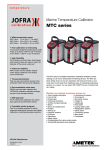
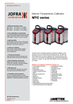
Type approved temperature calibrators to
optimize the performance of your vessel
Wide temperature range
MTC-140 A -17 to 140°C (-1 to 284°F)
MTC-320 A 33 to 320°C (91 to 608°F)
MTC-650 A 33 to 650°C (91 to 1202°F)
Fast calibration is timesaving
The specially designed heating block
profile heats up to 320°C (608°F) in just 4
minutes and to 650°C (1202°F) in only 10
minutes
The MTC series of portable temperature calibrators from
JF Instruments facilitates correct readings on all of your
temperature monitoring devices. The MTC dry-block
design does not use any hazardous hot liquid and heats
up and cools down much faster than traditional ways of
calibrating temperature sensors on a vessel. You can
reach 320°C (608°F) in just 4 minutes and do it safely.
High flexibility
You are not limited by fixed holes. Interchangeable insertion tubes are used to
match the diameter of your sensor-undertest
Enhanced stability
MVI circuitry ensures stability despite
mains supply variations in the engine
room environment
Timesaving features
Fast one-key-one-function access to the
automatic switch test and auto-stepping
Documentation made easy
RS232 communication interface and
JOFRACAL calibration software package
are part of the standard delivery
DNV approval
All JF Instruments calibrators are marine
type approved by Det Norske Veritas
Complete marine program
The MTC series is part of a complete
program of marine approved temperature,
pressure and signal calibrators; including
temperature sensors.
See more at www.jfinstruments.com
Maintain and calibrate monitoring devices for:
• Turbo-charger lubrication • Lubricating oil systems • Cylinder /
piston / fuel valve cooling media • Fuel oil inlet • Scavenge air •
Exhaust gas • Sea water cooling • Thrust / shaft plane / stern tube
bearings • Crankcase protection • Charge air • Turbine and gear
bearings • Uptake gas • Steam • Feed water • Servo oil pitch propeller
• Cooling water outlet • Purifiers • Refrigeration systems • Starting air
• Gland steam • Hydraulic systems • Condensing system • Oil burner
• Main steam • Generators • Condensers • Safety valves
ISO 9001 Manufacturer
-1-
Specification Sheet
SS-CP-2400-US
JF INSTRUMENTS
TM
Marine Temperature Calibrator
The MTC series features a large backlit display that is easy to
read even in well-lit areas. Units feature an informative display
that provides icons and information regarding the status of the
MTC and the calibration in-progress.
The practical Peltier element (electronic heating pump)
consists of many elements of semiconductor material
that are connected electrically in series and thermally in
parallel. These thermoelectric elements and their electrical
interconnections are mounted between two ceramic plates.
The plates serve to mechanically hold the overall structure
together and to electrically insulate the individual elements
from one another.
The MTC series also features an auto-step function. Using this
function you may stay in the control room or on the bridge and
monitor the temperature reading while the calibrator, located
in the engine room by the sensor, automatically steps through
a number of pre-programmed temperatures.
MVI - Improved temperature stability
MVI stands for ’’Mains power Variance Immunity’’.
Unstable mains power supplies are a major contributor to
on-site calibration inaccuracies. Traditional temperature
calibrators often become unstable in shipboard environments
where large electrical motors, heating elements, and other
devices are periodically cycled on and off. The cycling of
supply power can cause the temperature regulator to perform
inconsistently leading to both inaccurate readings and unstable temperatures.
Fast heating and cooling
The MTC-320 A and the MTC-650 A contain an innovative
heating block profile. This design heats up the MTC-320 A to
maximum temperature in just 4 minutes and the MTC-650 A
in only 10 minutes. The fast performance of the heating block
is due to the special profile that minimizes mass and yet, still
accepts an insertion tube
with a 1 in (26 mm) outer
diameter. This design is
a balanced compromise
between temperature
stability, homogeneity,
and rapid heating and
cooling.
The MTC series calibrators MTC-320 A and MTC-650 A
employ the MVI, thus avoiding such stability problems. The
MVI circuitry continuously monitors the supply voltage and
ensures a constant energy flow to the heating elements.
The MTC-140 A does not require the MVI circuitry because the
Peltier elements are energized with a stabilised DC voltage.
Easy-to-use, intuitive operation
All instrument controls may be performed from the front panel.
The heat source is positioned away from the panel. This design
helps to protect the operator.
The main functions on the MTC series are designed with onekey-one-function logic. This means that there are no submenus or difficult to remember multiple keystrokes necessary
to access primary functions.
The easy-to-read, backlit display features dedicated icons,
which help in identifying instrument conditions and operational
steps.
MTC-140 A heating/cooling block
The model MTC-140 A features Peltier elements. In 1834,
Jean Peltier, a French physicist found that an ’’opposite
thermocouple effect’’ could be observed when an electric
current was connected to a thermocouple. Heat would be
absorbed at one of the junctions and discharged at the
other junction. This effect is called the ’’PELTIER EFFECT’’.
-2-
Specification Sheet
SS-CP-2400-US
Set temperature
Re-calibration/adjustments
The ’’Up’’ and ’’Down’’ arrow keys allow the user to set the exact
temperature desired with a resolution of 0.1°C or °F.
The MTC series has a very easy and straightforward procedure
for re-calibration/adjustment. There is no need for a screwdriver
or PC software. The only thing you need is a reliable reference
thermometer.
Place the probe in the calibrator and follow the instructions on
the display. Third-party labs and calibration facilities will be
able to perform this function if a certificate from an independent
source is necessary. Of course, AMETEK can provide you
with a traceable calibration certificate from our labs when you
require a higher level of confidence.
Instrument setups
The MTC series stores the complete instrument setup,
including: engineering units, stability criteria, resolution,
display contrast, slope (ramp) rate, auto-step settings, and
maximum temperature.
Stability indicator
The bold checkmark (√) on the display indicates that the
calibrator has reached the desired set temperature and is
stable. The operator may change the stability criteria and
establish a greater sense of security in the calibration results.
A convenient countdown timer is activated five minutes before
the unit reaches stability.
Simplified calibration documentation
All MTC instruments are supplied with RS232 computer
interface and the JOFRACAL calibration software. This
software allows the user to customize his or her calibration
routines. The software is easy to use so you do not have to be
a programmer to configure your own calibration procedures.
After calibration you can print out certificates that contain
all necessary information for your ISM or similar quality
systems.
Automatic switch test
Operators can save a lot of time using the automatic
thermoswitch test function to find values for the ’’Open’’ and
’’Close’’ temperatures. Additionally, this feature displays the
hysteresis (deadband) between the two points. The feature
ensures a very high repeatability when testing thermoswitches. Simply press the SWITCH TEST key to activate the
function.
Auto-stepping
This feature saves manpower. The operator may stay in the
control room, or on the bridge, monitoring the output from the
sensor-under-test while the MTC series calibrator is placed in
the engine room and automatically changes the temperature
using a programmed step value and rate. Up to 9 different
temperature steps may be programmed, including the hold
time for each step.
This feature is also ideal for burning-in new sensors prior to
installation; this minimizes initial drift and allows for initial
testing.
The JOFRACAL software supports automatic calibration
for all JF-Instruments dry-block calibrators equipped with a
RS232 serial data interface. For semi-automatic calibrations,
the software also supports liquid baths, ice points, or other
dry-block heating and cooling sources. Using the software’s
SCENARIO function allows for combining instruments in
virtually any configuration.
The JOFRACAL software is able to store all your results in a
certificate database, a sensor database and an instrument
database, and use a database function history and search.
Maximum temperature
From the setup menu, the user can select the maximum
temperature limit for the calibrator. This function prevents
damage to the sensor-under-test caused by the application
of excessive temperatures. The feature also aids in reducing
drift resulting from extended periods of exposures to high
temperatures. This feature can be locked with an access
code.
-3-
Specification Sheet
SS-CP-2400-US
FUNCTIONAL SPECIFICATIONS
Heating time
Mains specifications
Voltage MTC-140/320/650 A .. 115V(90-127) 230V(180-254)
Frequency .............................................................. 45 - 65 Hz
Power consumption (max.) MTC-140 A ...................... 150 VA
Power consumption (max.) MTC-320 A / 650 A ........1150 VA
MTC-140 A
MTC-140 A
-17 to 23°C (1 to 73°F) ...................... 3 minutes
23 to 140°C (73 to 284°F).............. 15 minutes
MTC-320 A
MTC-650 A
33 to 320°C (91 to 608°F) ................ 4 minutes
33 to 650°C (91 to 1202°F) ............ 10 minutes
Cooling time
Temperature range
MTC-140 A
Maximum..........................................................140°C (284°F)
Minimum @ ambient temp. 0°C (32°F)........... -30°C (-22°F)
Minimum @ ambient temp. 23°C (73°F)............... -17°C (1°F)
Minimum @ ambient temp. 40°C (104°F) ............ -2°C (28°F)
MTC-140 A
MTC-140 A
MTC-140 A
100 to 0°C (212 to 32°F)................. 10 minutes
0 to -15°C (32 to 5°F)...................... 13 minutes
140 to 100°C (284 to 212°F)............. 2 minutes
MTC-320 A
MTC-650 A
320 to 100°C (608 to 212°F)........... 16 minutes
650 to 100°C (1202 to 212°F) ......... 28 minutes
Switch input (dry contact)
MTC-320 A .................................... 33 to 320°C (91 to 608°F)
MTC-650 A...................................33 to 650°C (91 to 1202°F)
Test voltage ............................................... Maximum 5 VDC
Test current ................................................Maximum 2.5 mA
Resolution (user-selectable)
JOFRACAL software
Selectable ........................................................1° or 0.1°C/°F
Minimum hardware requirements for JOFRACAL calibration
software.
Stability
•
MTC-140 A ............................................... ±0.05°C (±0.09°F)
MTC-320 A / 650 A ...................................... ±0.1°C (±0.18°F)
•
•
•
Measured after the stability indicator has been on for 10 minutes.
Measuring time is 30 minutes.
Time to stability (approximate)
•
•
MTC-140 A .................................................................... 5 min.
MTC-320 A / 650 A ....................................................... 8 min.
INTELTM 486 processor
(PENTIUMTM 200 MHz recommended)
16 MB RAM (32 MB recommended)
40 MB free disk space on hard disk prior to installation
Standard VGA (800 x 600, 16 colors) compatible screen
(1024 x 786, 256 colors recommended)
CD-ROM drive for installation of the program
1 free RS232 serial port
Accuracy
MTC-140 A .................................................... ±0.4°C (±0.7°F)
MTC-320 A .................................................... ±0.5°C (±0.9°F)
MTC-650 A.................................................... ±0.9°C (±1.6°F)
Specification when using the internal reference. (Load 4 mm OD
reference probe in the center of the insert).
Immersion depth
MTC-140 A (insulation included)................. . 4.5 in (115 mm)
MTC-320 A / 650A ........................................ 4.3 in (110 mm)
Engine rooms - testing the
temperature in exhaust gas
Savings
The exhaust gas temperature is
a very important factor. If the
temperature is too low, too little
fuel is let into the cylinder, and
if the temperature is too high,
too much fuel is let into the
cylinder.
Often a range of ±10°C (50°F)
is allowed, before an alarm is
activated. However, if calibration
is performed more often, this
range could be reduced and a
more economical combustion
could be achieved.
Engine rooms - testing the temperature in
exhaust gas
Application
On each cylinder, a thermometer has been placed
close to the exhaust gas outlet to measure the
temperature of the exhaust gas. This thermometer
breaks very often due to the impact from the exhaust
gas. As a consequence the temperature indication is
often inaccurate. The thermometers most frequently
have a scale from 350 to 450°C (662 to 842°F).
-4-
Specification Sheet
SS-CP-2400-US
PHYSICAL SPECIFICATIONS
KEY FEATURES
Automatic switch test
Instrument dimensions
Finds switching temp. ....................... Open, close, hysteresis
Slope rate, programable ............................... 0.1 to 9.9 °C/°F
MTC-140 A, MTC-320 A, MTC-650 A
L x W x H:................9.5 x 5.5 x 12.8 in (241 x 139 x 325 mm)
Auto stepping
Instrument weight
Programmable....................................................Up to 9 steps
Dwell time on each step .................................. Programmable
MTC-140 A ...................................................... 14.3 lb (6.5 kg)
MTC-320 A ............................................................ 11 lb (5 kg)
MTC-650 A...................................................... 14.1 lb (6.4 kg)
Enhanced stability
Unstable mains protection ................................. MVI Circuitry
Stability indication ............................................Yes, in display
Multi-information display
Stability indicator........................................... Bold checkmark
Countdown timer before stable ............................... 4 minutes
Temperature ......................... SET and READ simultaneously
Alphanumeric messages................................................... Yes
Calibration status icons..................................................... Yes
Training mode (heating/cooling block disabled)
Simulation of all functions ................................................. Yes
Simulating heating and cooling........Approx. 100° per minute
Service facilities
Adjustment of the unit from the keypad ............................ Yes
Self explanatory guide in display ...................................... Yes
Other information: Displays serial number, software revision
level, and last calibration date
Setup facilities
Stability criteria..............Extra time before ’’stable indication’’
is shown
Display resolution..............................................0.1° or 1°C/°F
Temperature units ................................................... °C and °F
Slope rate ....................................................0.1 to 9.9°/minute
Maximum temperature ....................... Any value within range
Type approval vertifcate
All JF Instruments calibrators are type approved by DET
NORSKE VERITAS.
Insert dimensions
MTC-140 A
Diameter x length ................ 0.75 x 3.9 in (19 mm x 100 mm)
MTC-320 A, MTC-650 A
Diameter x length ...................... 1 x 4.7 in (26 mm x 120 mm)
Weight of non-drilled insert (approximate)
MTC-140 A ..........................................................2.6 oz (75 g)
MTC-320 A ........................................................ 5.8 oz (170 g)
MTC-650 A...................................................... 17.8 oz (510 g)
Shipping (with std. accessories + carrying case)
Weight: MTC-140 A ....................................... 27.6 lb (12.5 kg)
Weight: MTC-320 A............................................. 24 lb (11 kg)
Weight: MTC-650 A ............................................ 27 lb (12 kg)
Size: L x W x H...... 19.9 x 9.1 x 16.3 in (507 x 232 x 415 mm)
Shipping (with std. accessories but no carrying case)
Weight: MTC-140 A ............................................. 22 lb (10 kg)
Weight: MTC-320 A............................................ 17.5 lb (8 kg)
Weight: MTC-650 A ...........................................21 lb (9.5 kg)
Size: L x W x H......16.4 x 9.8 x 14.6 in (465 x 255 x 470 mm)
Shipping (carrying case only)
Weight: ............................................................. 11 lb (5.0 kg)
Size: L x W x H...... 19.9 x 9.1 x 16.3 in (507 x 232 x 415 mm)
Miscellaneous
Serial data interface ............................... RS232 (9-pin Male)
Operating temperature.......................0 to 40°C (32 to 104°F)
Storage temperature ........................-20 to 50oC (-4 to 122oF)
Humidity ............................................................ 0 to 90% RH
Protection class ..............................................................IP-10
CE Conformity........... EN61326 : 1997/A1:1998 / corr. (2000)
......................................................EN61010-1 : 1993/A2:1995
-5-
Specification Sheet
SS-CP-2400-US
Marine approved temperature sensors
STANDARD DELIVERY
JF instruments also has a
series of temperature sensors
which are type approved by
classification societies for
marine applications such as
measuring exhaust gases,
cooling water for diesel
engines, and product or room
temperatures in refrigeration
stores. These sensors are
specially designed with
high enduance for vibration
according to IEC 68-2-6.
Approvals: Lloyds Register
of Shipping, Germanischer
Lloyd, Bureau Veritas and
Det Norske Veritas.
For fur ther information
please visit our web-page at
www.jfinstruments.com
Standard delivery MTC-140/320/650 A
•
•
•
•
•
•
•
•
•
•
•
MTC dry-block calibrator (user specified)
Mains power cable (user specified)
Traceable certificate - temperature performance
Insert (user specified)
Tool for insertion tubes
User manual
Test cables (1 x red, 1 x black)
3 pcs. insulation plugs for:
1/4, 3/8, 1/2 in (6, 10, 13 mm) sensors (MTC-140 A only)
Aluminium carrying case
RS232 cable
JOFRACAL software
ACCESSORIES
Part no.
Description
105337
123408
122832
60F174
122822
60F135
60F139
60F138
60F137
60F141
60F140
60F143
60F142
60F136
104203
104216
60F170
123469
MTC series, user manual
Carrying case
Cleaning brush, 4 mm (3/Pkg)
Cleaning brush, 6 mm (3/Pkg)
Cleaning brush, 8 mm (3/Pkg)
Mains cable, 115V, USA, Type B
Mains cable, 220V, Australia, Type F
Mains cable, 220V, Italy, Type E
Mains cable, 220V, South Africa, Type D
Mains cable, 230V, Denmark, Type G
Mains cable, 230V, Europe, Type A
Mains cable, 230V, Israel, Type I
Mains cable, 230V, Switzerland, Type H
Mains cable, 240V, UK, Type C
Test cable set
Thermal protection shield
Insert removal tool
Insulation plug (MTC-140 A only) 3 pcs.
for 1/4 in (6 mm), 3/8 in (10 mm), 1/2 in (13 mm)
Insulation tube 4 in (100 mm)
10 insulation plates
RS232 cable
JOFRACAL software
65-F100
105173
105366
124915
Carrying case - part no. 123408
The protective carrying case
ensures safe transportation
and storage of the instrument
and all associated equipment.
The carrying case is included
in the standard delivery.
Thermal Protection Shield - part no. 104216
An external heat shield is
available and may be placed
on top of the calibrator to
reduce the hot air stream
around the sensor-under-test.
This is especially important
for testing thermocouples
having
head-mounted
transmitters with cold-junction
compensation.
Inserts, heat shield, and cleaning brushes
Always use the original inserts where material and physical
dimensions have been optimized. A drilling guide is included
if you buy undrilled inserts.
Use the cleaning brushes to clean the bores in your inserts
when necessary.
Insulation tube and plates - part no. 65F100 and 105173
Improve your calibration
uncertainty by insulating the
sensor-under-test.
Minimize the heat dissipation
from the top of the block and
through the sensor-undertest.
-6-
Specification Sheet
SS-CP-2400-US
Inserts - undrilled
INSERTS FOR MTC SERIES
General inserts description
Inserts
Inserts for MTC-140 A and MTC-320 A are made of aluminium.
Inserts for MTC-650 A are made of brass.
5-pack, undrilled
insertion tubes
140 A
part no.
320 A
part no.
650 A
part no.
60F448
100175
100194
All specifications on hole sizes refer to the outer diameter of
the sensor-under-test.
The correct clearance size is applied in all predrilled inserts.
Specially drilled inserts are available on request.
Inserts - predrilled - metric
Probe
diameter
140 A
part no.
320 A
part no.
650 A
part no.
3 mm
4 mm
5 mm
6 mm
7 mm
8 mm
9 mm
10 mm
11 mm
12 mm
13 mm
14 mm
15 mm
16 mm
18 mm
20 mm
Set of above inserts
Multi-hole M01
123428
60F451
123429
60F453
123430
105185
105186
105187
123431
123432
123433
N/A
N/A
N/A
N/A
N/A
124679
123479
123436
100177
123437
100179
123438
100182
100183
100185
100188
100186
60F339
100190
100191
123439
123440
123441
124681
123475
123444
100196
123445
100198
122516
100201
100202
105188
100204
100206
105189
100208
100209
123446
122517
122518
124685
123476
Undrilled inserts
(MTC-140 A)
Undrilled inserts
(MTC-320 A)
(MTC-650 A)
3 mm
4 mm
3/16 in
6 mm
5 mm
Multi-hole M01
(MTC-140 A)
1/8 in
1/4 in
Multi-hole M02
(MTC-140 A)
9 mm
4 mm
3 mm
3/8 in
6 mm
*Note: MTC-140 only: All multi-hole inserts are delivered with a
matching insulation plug.
5 mm
Multi-hole M01
(MTC-320 A)
(MTC-650 A)
Inserts - predrilled - imperial (inch)
1/8 in
3/16 in
1/4 in
Probe
diameter
140 A
part no.
320 A
part no.
650 A
part no.
1/8 in
3/16 in
1/4 in
5/16 in
3/8 in
7/16 in
1/2 in
9/16 in
5/8 in
11/16 in
3/4 in
13/16 in
7/8 in
Set of above inserts
Multi-hole M02
60F450
60F452
60F454
60F456
60F458
60F460
60F462
60F464
60F466
N/A
N/A
N/A
N/A
124680
123480
100176
100178
100180
100181
100184
100187
100189
60F344
100192
60F348
100193
60F352
60F354
124682
123477
100195
100197
100199
100200
100203
100205
100207
60F408
100210
60F412
100211
60F416
60F418
124686
123478
Multi-hole M02
(MTC-320 A)
(MTC-650 A)
*Note: MTC-140 only: All multi-hole inserts are delivered with a
matching insulation plug.
-7-
ORDERING INFORMATION
temperature
software
Model MTC series dry-block temperature calibrators
Order number
MTC140A
MTC320A
MTC650A
115
230
A
B
C
D
E
F
G
H
I
Description
Base model number - 1st thru 7th characters
MTC-140 A, -17 to 140°C (-1 to 284°F)
MTC-320 A, 50 to 320°C (122 to 608°F)
MTC-650 A, 50 to 650°C (122 to 1202°F)
Power supply - 8th thru 10th characters
115VAC, 50/60Hz
230VAC, 50 Hz
Mains power cable type - 11th characters
EUROPEAN, 230V,
USA/CANADA, 115V
UK, 240V
SOUTH AFRICA, 220V
ITALY, 220V
AUSTRALIA, 240V
DENMARK, 230V
SWITZERLAND, 220V
ISRAEL, 230V
Insert type and size - 12th thru 14th characters
003
Metric, pre-drilled, 3 mm
004
Metric, pre-drilled, 4 mm
005
Metric, pre-drilled, 5 mm
006
Metric, pre-drilled, 6 mm
007
Metric, pre-drilled, 7 mm
008
Metric, pre-drilled, 8 mm
009
Metric, pre-drilled, 9 mm
010
Metric, pre-drilled, 10 mm
011
Metric, pre-drilled, 11 mm
012
Metric, pre-drilled, 12 mm
013
Metric, pre-drilled, 13 mm
014
Metric, pre-drilled, 14 mm
(Not available for MTC-140)
015
Metric, pre-drilled, 15 mm
(Not available for MTC-140)
016
Metric, pre-drilled, 16 mm
(Not available for MTC-140)
018
Metric, pre-drilled, 18 mm
(Not available for MTC-140)
020
Metric, pre-drilled, 20 mm
(Not available for MTC-140)
125
Inch, pre-drilled, 1/8 in
187
Inch, pre-drilled, 3/16 in
250
Inch, pre-drilled, 1/4 in
312
Inch, pre-drilled, 5/16 in
375
Inch, pre-drilled, 3/8 in
437
Inch, pre-drilled, 7/16 in
500
Inch, pre-drilled, 1/2 in
562
Inch, pre-drilled, 9/16 in
625
Inch, pre-drilled, 5/8 in
688
Inch, pre-drilled, 11/16 in
(Not available for MTC-140)
750
Inch, pre-drilled, 3/4 in
(Not available for MTC-140)
813
Inch, pre-drilled, 13/16 in
(Not available for MTC-140)
875
Inch, pre-drilled, 7/8 in.
(Not available for MTC-140)
M01
Multi-hole insert type 1
M02
Multi-hole insert type 2
Options - 15th thru 18th characters
C
Carrying case (standard)
F
Traceable certificate (standard for Europe, Asia, Australia and Africa)
G
NIST traceable certificate (standard for Western Hemisphere)
H
DANAK accredited certificate
X
Placeholder character for unused option
pressure
signal
AMETEK
Calibration Instruments
offers a complete range of calibration
equipment for pressure, temperature,
and signal - including software.
JOFRA Temperature standards
Portable precision thermometer.
Dry-block calibrators: 4 series, more
than 20 models - featuring speed,
portability, accuracy, and advanced
documenting functions.
M&G Primary pressure standards
Pneumatic floating-ball or hydraulic
piston deadweight testers - easy-touse with accuracies up to 0.015% of
reading.
JOFRA Pressure standards
Convenient electronic systems
ranging from -1 to 700 bar (25 inHg to
10,000 psi) - multiple choices of pressure ranges, pumps, and accuracies,
fully temperature-compensated for
problem-free and accurate field use.
JOFRA Signal calibration
Process signal measurement and
simulation for easy control loop calibration and measurement tasks - from
handheld field instruments for multi
or single signals to laboratory reference level bench top instruments.
MTC650A 230 A M01 CFXX Sample order number (all 18 characters)
JOFRA MTC-650 A series dry-block, 230VAC power with European
power cord, pre-drilled multi-hole type 1 (1 x 3 mm, 1 x 4 mm.,
1 x 5 mm, 1 x 6 mm, 1 x 9 mm) including carrying case and
traceable certificate.
www.ametekcalibration.com
www.jfinstruments.com
AMETEK Test & Calibration Instruments AMETEK Denmark A/S
USA, Florida Tel: +1 (727) 536-7831
Denmark Tel: +45 4816 8000
Tel:
(800) 527-9999
[email protected]
[email protected]
AMETEK GmbH
AMETEK Singapore Pte. Ltd.
Germany Tel: +49 2159 9136 0
Singapore
Tel: +65 6 484 2388
[email protected]
[email protected]
...because calibration is
a matter of confidence
AMETEK is a leading global manufacturer of electrical and electromechanical products
for niche markets. AMETEK’s annual sales exceed $1billion. NYSE (AME) since 1930.
Operations are in US, Europe and Asia, with about 1/3 of sales to markets outside the US.
Distributor:
ISO 9001 Manufacturer
Pub Code SS-CP-2400-US Issue 0408
Information within this document is subject to change without notice.
-8-
Copyright 2004 by AMETEK, Inc.
AMETEK is a registered trademark of AMETEK, Inc.