1
temperature
Specification Sheet
SS-CP-2285-US
TM
JOFRA ATC series
Advanced
Temperature
Calibrators
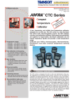
The JOFRATM ATC series (Advanced Temperature Calibrators) combines the accuracy of laboratory temperature
sources with the speed and portability of field dry block
calibrators. The unique dual-zone design sets new standards for optimum temperature performance.
Wide temperature range
ATC-155
ATC-156
ATC-157
ATC-320
ATC-650
-24 to 155°C (-11 to 311°F)
-24 to 155°C (-11 to 311°F)
-45 to 155°C (-49 to 311°F)
33 to 320°C (91 to 608°F)
33 to 650°C (91 to 1202°F)
Improved temperature homogeneity
The unique dual-zone block ensures
good temperature homogeneity in the
critical calibration zone of the heating/
cooling block.
High accuracy
NOW... DUAL-ZONE TECHNOLOGY
in the entire temperature range
-45 to 650°C (-49 to 1202°F)
Using the internal reference or the
external reference probe. 4-wire TrueOhm-Measurement technology is used.
Enhanced stability
MVI circuitry ensures temperature
stability despite mains supply variations.
Cost effective calibration system
Stand alone operation eliminates the
need for secondary equipment and PC.
Universal inputs handle multiple type
temperature sensors.
Timesaving features
Up- and download complete calibration
tasks. Autostepping, switch testing and
many more features make the daily use
smoth and fast.
Documentation made easy
RS-232 communication and calibration
software AMECAL-TEMPERATURE are
standard delivery.
PRODUCT DESCRIPTION
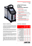
The ATC series calibrators are available in four different temperature ranges
and each version in two models, A and B.
All JOFRA ATC series models (except the ATC-155) feature the unique
dual-zone heating block - designed for optimum performance and superior
temperature homogeneity throughout the block. This new design has a
performance equivalent to a liquid temperature bath. The ATC-157 (super
cooler) features the widest temperature range for a cooling dry-block on
the market today.
Each ATC dry-block calibrator may be used to perform fully automatic
calibration routines without using an external computer. Use the computer
for full upload and download capabilities. Units may also be supplied with
inputs for external reference sensors and for sensors-under-test. All ATC
calibrators feature RS-232 serial communication and standard delivery also
includes the AMECAL-TEMPERATURE calibration PC software.
-1-
SS-CP-2285-US
MVI - Improved temperature stability
The ATC series of calibrators provide precision temperature
calibration of sensors; whatever the type or format. This is
accomplished through an innovative dual-zone heating block.
All JOFRA ATC models (except the ATC-155) feature a dualzone heating block. Each heating zone is independently
controlled for precision temperature measurement. The
homogeneity in the lower part of the block is close to that
of a laboratory liquid bath. The lower zone ensures optimum
heat dissipation throughout the entire block. The upper zone
compensates for heat loss from the sensor-under-test and
from the top of the block. This design also eliminates the
need for insulation of the sensors-under-test and makes
it possible to calibrate liquid-filled and other mechanical
sensors.
MVI stands for ’’Mains power Variance Immunity’’.
Unstable mains power supplies are a major contributor to
on-site calibration inaccuracies. Traditional temperature calibrators often become unstable in production environments
where large electrical motors, heating elements, and other
devices are periodically cycled on or off. The cycling of
supply power can cause the temperature regulator to perform
inconsistently leading to both inaccurate readings and unstable temperatures.
Main Zone
Upper Zone
Unique temperature performance
Sensor-under-test
Temperature
difference
The JOFRA ATC series calibrators ATC-320 and ATC-650
employ the MVI, thus avoiding such stability problems. The
MVI circuitry continuously monitors the supply voltage and
ensures a constant energy flow to the heating elements. All
other ATC models run on stabilized DC voltage and thus do
not need the MVI circuitry.
Set
temperature
Internal reference
Highest accuracy (model B only)
ATC heating and cooling models
The models with both heating and cooling capabilities
(ATC-155, -156, -157) feature the Peltier element multi-stagetechnology. This both improves efficiency and extends the life
of the »electronic heat pump«. The JOFRA ATC-157 goes as
deep as minus 71°C (128°F) below ambient temperature.
Peltier effect (ATC-155, -156, -157)
In 1834, Jean Peltier, a French physicist found that an ’’opposite thermocouple effect’’ could be observed when an electric
current was connected to a thermocouple. Heat would be
absorbed at one of the junctions and discharged at the
other junction. This effect is called the ’’PELTIER EFFECT’’.
The practical Peltier element (electronic heating pump) consists of many elements of semiconductor material connected
electrically in series and thermally in parallel. These thermoelectric elements and their electrical interconnections are
mounted between two ceramic plates. The plates serve to
mechanically hold the overall structure together and to electrically insulate the individual elements from one another.
-2-
ATC series calibrators may be supplied with a built-in reference thermometer for use with an external probe. This feature allows one instrument to provide the freedom and flexibility to perform calibrations at the process site while maintaining a high accuracy.
A special 90° angled external reference sensor has been
designed to accommodate sensors with a transmitter head,
Specification Sheet
SS-CP-2285-US
top connector or similar arrangement.
(More information about the JOFRA STS-100 reference
sensors in the seperate specification sheet: SS-CP-2279)
The user can decide whether to read the built-in reference
sensor or the more accurate angled reference sensor from
the calibrator’s large, easy-to-read LCD display. The external
sensor and the internal sensor are independent of one
another. Downloading of reference sensor linearization is
done via a personal computer.
Easy-to-use, intuitive operation
All instrument controls may be performed from the front
panel. The heat source is positioned away from the panel
which helps protecting the operator.
The ATC keyboard is equipped with five, positive feedback
function keys. They correspond to the text in the display and
change functionality based on instrument operations. There
are also dedicated function keys with permanent functions.
SET-Follows-TRUE (model B only)
Available on B models only, the “SET-Follows TRUE” causes
the instrument to tune-in so that the temperature of the
external reference “TRUE” is related to the desired “SET”
temperature. This is used when it is critical that the temperature in the block is matched to the desired temperature
as measured with an accurate external reference sensor.
This function is ideal for calibrating gas correctors or other
custody transfer applications. It is extremely beneficial in the
calculation process.
Reading of sensor-under-test (model B only)
The ATC series model B is equipped with built-in converters
(inputs) that measure virtually any type of temperature
sensor including:
•
•
•
•
•
•
thermostats
resistance thermometers
thermocouples
transmitters
milliamps (mA)
voltage (V)
The easy-to-read, backlit display is large with a high contrast
that is readible even in high ambient light conditions. The
display is easily read from all angles and from a distance
without parallax problems. The display also features icons
which help identifying instrument conditions and operational
steps.
Set temperature
The “Set temperature” feature allows the user to set the exact
desired temperature with a resolution of 0.01°.
ATC series calibrators can be user-programmed for completely automated temperature calibrations. Once the unit
is set up, the instrument operates itself by performing the
configured calibration routine. All calibration data is stored
and available for uploading and generating exact calibration
certificates or reports.
Switch test (model B only)
Users may perform a thermoswitch test and find “Open”,
“Closed” and the hysteresis (deadband) automatically. The
instrument retains the last five tests. This information cannot
be uploaded to a personal computer.
Auto stepping
Up to 20 different temperature steps may be programmed
including the hold time for each step. Upon completion of
an auto step routine, the user can easily read the results
for the sensor-under-test. Up to five (5) auto step results are
retained.
Enhanced stability
A stability indicator shows when the ATC calibrator has
reached the desired temperature and is stable. The user
may change the stability criteria, external reference and the
sensor-under-test quickly and simply. The stability criteria are
the user’s security for a correct calibration. A count-down
timer is displayed next to the temperature read-out.
Instrument setups
The ATC series allows the user to store up to nine (9)
complete instrument setups. You may store all sorts of
information including temperature units, stability criteria, use
of external reference sensor, resolution, sensor-under-test
(SUT), conversion to temperature, display contrast, etc. The
setup may be recalled at any time.
-3-
SS-CP-2285-US
The AMECAL-TEMPERATURE software supports all JOFRA
dry-block calibrators equipped with an RS-232 serial data
interface, the JOFRA DTI-1000 reference thermometer and
applications using liquid baths, ice point or other dry-block
heat sources. Using the software’s “SCENARIO” function,
instruments may be combined in virtually any configuration.
Maximum temperature
From the setup menu, the user can select the maximum
temperature limit for the calibrator. This function prevents
damage to the sensor-under-test caused by the application
of excessive temperatures. The feature also aids in reducing
drift resulting from extended periods of exposures to high
temperatures. This feature can be locked with an access
code.
Simplified calibration documentation
All ATC series calibrators are provided with the AMECALTEMPERATURE software. This WINDOWS®-based software allows the user to customize his or her calibration routines. The software is easy to use so you do not need to be
a programmer to configure your own calibration procedures.
The software features prompts, menus and help functions
that guide you through the configuration process.
Calibrations are collected and stored as “Work orders” in
a file and downloaded to the calibrator from a personal computer using a standard RS-232 interface cable. The ATC
calibrator stores the calibration procedure and may be taken
out to the process site without using a personal computer.
This allows your ATC calibrator to:
•
•
As found/as left (model B only)
The JOFRA ATC series calibrator automatically handles
“As Found/As Left” calibrations. The calibrator stores both
results. The first performed calibration is “As found” and
the last performed calibration is the “As left”, regardless of
the number of calibrations/adjustments that may have been
made in between.
Operate as a stand-alone instrument, using
advanced calibration routines without the assistance of a personal computer on site;
SYNC output
An output is located directly on the front of the ATC calibrator.
This output signals when the instrument is stable and may be
used with ancillary devices such as video recorders, digital
cameras or as an input to a data logging device. The SYNC
output may be useful for automating and documenting your
calibrations when calibrating external reading devices.
Prevent unauthorized changes to a calibration
routine. Personnel who are not authorized to
alter a calibration routine cannot do so.
Once all calibrations are
completed, the data may be
uploaded to the AMECALTEMPERATURE software for
post-processing and printing
of certificates. The calibration data collected may be
stored on the personal computer for later recall or analysis.
Calibration (model B only)
Users may perform or read the results of the calibration tasks
directly on the instrument. When calibrating an indicating
device, users may key in the results during or after the test.
Using the “Calibration info” function, the user may view the
complete calibration task, including the “Scenario” before the
calibration takes place.
-4-
Specification Sheet
SS-CP-2285-US
FUNCTIONAL COMPARISON
Feature
Dual-zone heating/cooling block (not ATC-155)
MVI - Mains Variance Immunity (or similar)
Stability indicator
Automatic step function
Calibration software included
SYNC output (for external recording device)
Display resolution 0.01°
Inserts storage compartment
Graphical LCD display
Programmable max. temperature
Input for RTD, TC, V, mA
4-20 mA transmitter input incl. 24 VDC supply
All inputs scalable to temperature
Automatic switch test (open, close and hysteresis)
External precision reference probe input
Download of calibration work orders from PC
Upload of calibration results (as found & as left)
“SET” follows “TRUE”
GUIDELINE EA-10/13
Model
A
B
•
•
•
•
•
•
•
•
•
•
•
•
•
•
•
•
•
•
•
•
•
•
•
•
•
•
•
•
EA means European Accreditation. The purpose of this organization is to maintain and develop multilateral agreements
within member and non-member accreditation bodies to
achieve universal acceptance of accredited certificates and
reports and interchange of technical knowledge among the
countries.
EA has given birth to a new “Guideline on the Calibration of
Temperature Block Calibrators”, including a complete uncertainty budget. Publication reference is EA-10/13.
Besides measuring absolute temperature by representative
set points, the calibrator must also be investigated for the
following: Axial temperature homogeneity, temperature difference between the borings, influence on the temperature in
the measurement zone due to different loading, stability with
time, and temperature deviation due to heat conduction.
AMETEK CALIBRATION INSTRUMENTS is convinced that
this guideline will become the standard of how to specify/
qualify a dry-block temperature calibrator in the future.
-5-
SS-CP-2285-US
ATC-156
-24 to 23°C (-11 to 73°F) ......................................... 4 minutes
23 to 100°C (73 to 212°F) ....................................... 9 minutes
100 to 155°C (212 to 311°F) .................................. 10 minutes
FUNCTIONAL SPECIFICATIONS
Mains specifications
ATC-157
-45 to 23°C (-49 to 73°F) ........................................ 6 minutes
23 to 100°C (73 to 212°F) ....................................... 8 minutes
100 to 155°C (212 to 311°F) .................................... 9 minutes
ATC-155/156/157/320 ............. 115V(90-127) 230V(180-254)
ATC-650 ................................ 115V(100-127) 230V(200-254)
Frequency .............................................................. 45 - 65 Hz
Power consumption (max.) ATC-155 .......................... 200 VA
Power consumption (max.) ATC-156/157 ................... 300 VA
Power consumption (max.) ATC-320/650 .................1150 VA
ATC-320
50 to 320°C (122 to 608°F) ..................................... 7 minutes
Temperature range
ATC-650
50 to 320°C (122 to 608°F) ................................... 10 minutes
50 to 650°C (122 to 1202°F) ................................. 27 minutes
ATC-155/156 Maximum.................................... 155°C (311°F)
Minimum @ ambient temp. 0°C (32°F)........... -40°C (-40°F)
Minimum @ ambient temp. 23°C (73°F)............ -24°C (-11°F)
Minimum @ ambient temp. 40°C (104°F) .......... -12°C (10°F)
Cooling time
ATC-155
155 to 100°C (311 to 212°F) .................................... 3 minutes
100 to 23°C (212 to 73°F) ..................................... 10 minutes
23 to 0°C (73 to 32°F) ............................................. 7 minutes
0 to -20°C (32 to -4°F)........................................... 15 minutes
ATC-157 Maximum ........................................... 155°C (311°F)
Minimum @ ambient temp. 0°C (32°F)............-57°C (-71°F)
Minimum @ ambient temp. 23°C (73°F)........... -45°C (-49°F)
Minimum @ ambient temp. 40°C (104°F) .........-31°C (-24°F)
ATC-320 ...................................... 33 to 320°C (91 to 608°F)
ATC-650 .......................................33 to 650°C (91 to 1202°F)
ATC-156
155 to 100°C (311 to 212°F) .................................... 4 minutes
100 to 23°C (212 to 73°F) ....................................... 9 minutes
23 to 0°C (73 to 32°F) ............................................. 6 minutes
0 to -20°C (32 to -4°F)........................................... 13 minutes
Resolution (user-selectable)
All temperatures ......................................... 1° or 0.1° or 0.01°
Stability
ATC-157
155 to 100°C (311 to 212°F) .................................... 3 minutes
100 to 23°C (212 to 73°F) ....................................... 6 minutes
23 to 0°C (73 to 32°F) ............................................. 3 minutes
0 to -30°C (32 to -22°F) .......................................... 9 minutes
-30 to -45°C (-22 to -45°F) .................................... 15 minutes
ATC-155/156/157....................................... +0.02°C (+0.04°F)
ATC-320 .................................................... +0.02°C (+0.04°F)
ATC-650 .................................................... +0.03°C (+0.06°F)
Measured after the stability indicator has been on for 10 minutes.
Measuring time is 30 minutes.
Time to stability (approximate)
ATC-320
320 to 100°C (608 to 212°F) ................................. 22 minutes
100 to 50°C (212 to 122°F) .................................. 20 minutes
All models ............................................................. 10 minutes
Accuracy (model B)
ATC-155/156/157 B ................................... +0.04°C (+0.07°F)
ATC-320 B..................................................+0.07°C (+0.13°F)
ATC-650 B..................................................+0.11°C (+0.20°F)
ATC-650
650 to 100°C (1202 to 212°F)................................ 43 minutes
100 to 50°C (212 to 122°F) ................................... 25 minutes
12 month period. Relative to reference standard. Specification by
use of the external reference.
SYNC output (dry contact)
Switching voltage ..................................... Maximum 30 VDC
Switching current .......................................Maximum 100 mA
Accuracy (model A+B)
ATC-155/156/157 A+B ...............................+0.19°C (+0.34°F)
ATC-320 A+B ............................................ +0.26°C (+0.47°F)
ATC-650 A+B ............................................ +0.39°C (+0.70°F)
INPUT SPEC’S (B MODELS ONLY)
12 month period. Specification by use of the internal reference.
All input specifications apply with the calibrator’s dry-block running
at the respective temperature (stable plus an additional 20 minute
period). Where the input measuring range is out of the calibrator’s
range, the SET temperature is either MIN. or MAX.
Radial homogeneity (difference between holes)
ATC-155/156/157............................................0.02°C (0.04°F)
ATC-320 .........................................................0.01°C (0.02°F)
ATC-650 .......................................................0.05°C (0.09°F)
Transmitter supply
Immersion depth
Output voltage................................................... 24VDC +10%
Output current ............................................. Maximum 25 mA
ATC-155/156/157.......................................... 160 mm (6.3 in.)
ATC-320/650.................................................150 mm (5.9 in.)
Transmitter input mA
Heating time
Range.....................................................................0 to 24 mA
Accuracy (12 months) ................. +0.01% Rdg. +0.015% F.S.
ATC-155
-24 to 23°C (-11 to 73°F) ......................................... 4 minutes
23 to 100°C (73 to 212°F) ..................................... 10 minutes
100 to 155°C (212 to 311°F) .................................. 13 minutes
Voltage input VDC (B models only)
Range:.................................................................. 0 to 12VDC
Accuracy (12 months) ............... +0.005% Rdg. +0.015% F.S.
-6-
Specification Sheet
SS-CP-2285-US
Switch input (B models only)
Thermocouple input
Switch dry contacts
Test voltage ................................................ Maximum 5 VDC
Test current ................................................Maximum 2.5 mA
Range .......................................................................... 78 mV
F.S. (Full Scale)............................................................ 78 mV
Accuracy (12 months) ....................0.01% rdg. + 0.005% F.S.
RTD reference input (B models only)
TC
Type
Type..................... 4-wire RTD with true ohm measurements1
F.S. (Full Scale).........................................................350 ohm
Accuracy (12 months) ................±0.003% rdg. + 0.002% F.S.
RTD
Type
Temperature
°C
°F
E
12 Months
°C
°F
-50
-58
±0.024
±0.042
0
32
±0.026
±0.046
155
311
±0.032
±0.057
Reference 320
608
±0.038
±0.068
650
1202
±0.047
±0.084
700
1292
±0.056
±0.101
Note 1: True ohm measurement are an effective method to eliminate
errors from induced thermoelectrical voltages
Pt100
J
K
RTD input
Type of RTD .................................................... 2-, 3- or 4-wire
F.S. (range) ......................................... 350 ohm or 2900 ohm
Accuracy (12 months) ................±0.005% rdg. + 0.005% F.S.
RTD
Type
Pt1000
Pt500
Pt100
Pt50
Pt10
Cu100
Cu50
Temperature
°C
°F
-50
0
155
320
500
-50
0
155
320
500
-50
0
155
320
650
700
-50
0
155
320
650
700
-50
0
155
320
650
700
-50
0
150
-50
0
150
-58
32
311
608
932
-58
32
311
608
932
-58
32
311
608
1202
1292
-58
32
311
608
1202
1292
-58
32
311
608
1202
1292
-58
32
302
-58
32
302
T
12 Months
°C
°F
±0.046
±0.050
±0.061
±0.071
±0.087
±0.083
±0.087
±0.100
±0.111
±0.130
±0.054
±0.058
±0.069
±0.079
±0.106
±0.112
±0.098
±0.103
±0.116
±0.128
±0.161
±0.169
±0.453
±0.462
±0.495
±0.524
±0.610
±0.620
±0.050
±0.052
±0.060
±0.090
±0.093
±0.100
±0.083
±0.090
±0.110
±0.127
±0.156
±0.149
±0.157
±0.180
±0.200
±0.235
±0.097
±0.104
±0.124
±0.142
±0.191
±0.202
±0.176
±0.185
±0.209
±0.230
±0.290
±0.303
±0.815
±0.831
±0.891
±0.943
±1.098
±1.116
±0.090
±0.094
±0.108
±0.162
±0.167
±0.180
R
S
B
N
XK
U
Temperature
°C
°F
-50
0
155
320
650
1000
-50
0
155
320
650
1200
-50
0
155
320
650
1372
-50
0
155
320
400
-50
0
155
320
650
1760
-50
0
155
320
650
1768
250
320
650
1820
-50
0
155
320
650
800
-50
0
155
320
650
800
-50
0
155
320
600
-58
32
311
608
1202
1832
-58
32
311
608
1202
2192
-58
32
311
608
1202
2502
-58
32
311
608
752
-58
32
311
608
1202
3200
-58
32
311
608
1202
3214
482
608
1202
3308
-58
32
311
608
1202
1472
-58
32
311
608
1202
1472
-58
32
311
608
1112
12 Months
°C
°F
±0.08
±0.07
±0.07
±0.08
±0.11
±0.15
±0.10
±0.08
±0.08
±0.10
±0.12
±0.19
±0.11
±0.10
±0.11
±0.12
±0.16
±0.28
±0.12
±0.10
±0.09
±0.09
±0.10
±1.31
±0.78
±0.50
±0.42
±0.41
±0.50
±0.98
±0.78
±0.50
±0.46
±0.45
±0.52
±1.57
±0.99
±0.69
±0.48
±0.16
±0.15
±0.14
±0.14
±0.16
±0.17
±0.07
±0.06
±0.06
±0.07
±0.11
±0.12
±0.12
±0.10
±0.09
±0.09
±0.10
±0.14
±0.12
±0.12
±0.14
±0.20
±0.28
±0.17
±0.14
±0.15
±0.18
±0.19
±0.34
±0.20
±0.18
±0.20
±0.22
±0.28
±0.50
±0.22
±0.18
±0.16
±0.17
±0.17
±2.35
±1.40
±0.90
±0.75
±0.74
±0.90
±1.77
±1.40
±0.90
±0.83
±0.81
±0.94
±2.83
±1.78
±1.23
±0.86
±0.29
±0.27
±0.24
±0.25
±0.28
±0.31
±0.13
±0.11
±0.12
±0.13
±0.19
±0.22
±0.21
±0.18
±0.17
±0.17
±0.19
If automatic cold junction compensation is used, the specification for
CJ is ±0.40°C (±0.72°F).
-7-
SS-CP-2285-US
STANDARD DELIVERY
PHYSICAL SPECIFICATIONS
Instrument dimensions (L x W x H)
Standard delivery ATC-155, -156, -157, -320 and -650
All models ........... 352 x 156 x 360 mm (13.9 x 6.1 x 14.2 in.)
•
•
•
•
•
Instrument weight
ATC-155......................................................... 12.4 kg (27.3 lb)
ATC-156.........................................................12.2 kg (26.9 lb)
ATC-157......................................................... 13.1 kg (28.9 lb)
ATC-320 ........................................................10.2 kg (22.5 lb)
ATC-650 ........................................................ 12.1 kg (26.7 lb)
•
Insert dimensions
•
•
•
•
•
•
ATC-155/156 ............................. 30 x 150 mm (1.18 x 5.91 in.)
ATC-157 ................................... 20 x 150 mm (0.79 x 5.91 in.)
ATC-320/650 ..............................30 x 160 mm (1.18 x 6.3 in.)
Weight of non-drilled insert (approximate)
ATC-155/156.........................................................290 g (9 oz)
ATC-157............................................................. 130 g (4.6 oz)
ATC-320/650.................................................. 940 g (33.2 oz)
ATC dry-block calibrator (user specified)
Mains power cable (user specified)
Traceable certificate - temperature performance
Insert (user specified)
3 pcs. insulation plugs for 6, 10, 16 mm sensors
(ATC-155/156 only)
3 pcs. insulation plugs for 5, 8, 11 mm sensors
(ATC-157 only)
Tool for insertion tubes
RS-232 cable
Software, AMECAL-TEMPERATURE
Software, AMETRIM-ATC to adjust the ATC series
Users’ manual (multi-language)
Reference manual (English)
Model B instruments contain the following extra items:
•
Test cables (2 x red, 2 x black)
•
Traceable certificate - input performance
Shipping (including optional carrying case)
ATC-155......................................................... 22.4 kg (49.4 lb)
ATC-156.........................................................22.2 kg (48.9 lb)
ATC-157......................................................... 23.1 kg (50.9 lb)
ATC-320 ........................................................ 20.7 kg (45.6 lb)
ATC-650 ........................................................22.6 kg (49.8 lb)
AMECAL-TEMPERATURE software
Size: L x W x H 659x309x514 mm (26x12.2x20.2 in.)
Listed are the minimum hardware requirements needed for
running the AMECAL-TEMPERATURE calibration software.
Shipping (without carrying case)
•
ATC-155......................................................... 16.7 kg (36.8 lb)
ATC-156.........................................................16.5 kg (36.4 lb)
ATC-157......................................................... 17.4 kg (38.4 lb)
ATC-320 ........................................................... 15 kg (33.1 lb)
ATC-650 ........................................................ 16.9 kg (37.2 lb)
•
•
•
Size: L x W x H 570 x 235 x 440 mm (22.4 x 9.3 x 17.3 in.)
•
•
Shipping (carrying case only)
Weight: ........................................................... 6.0 kg (13.2 lb)
Size: L x W x H 659 x 309 x 514 mm (26 x 12.2 x 20.2 in.)
Miscellaneous
Serial data interface ........................... RS-232C (9-pin Male)
Operating temperature.......................0 to 40°C (32 to 104°F)
Storage temperature ........................-20 to 50oC (-4 to 122oF)
Humidity ............................................................ 0 to 90% RH
Protection class ..............................................................IP-10
CE Conformity................................. EN61326 : 1997/A1:1998
......................................................EN61010-1 : 1993/A2:1995
-8-
INTELTM 486 processor
(PENTIUMTM 200 MHz recommended)
16 MB RAM (32 MB recommended)
40 MB free disk space on hard disk prior to installation
Standard VGA (640 x 480, 16 colors) compatible screen
(800 x 600, 256 colors recommended)
CD-ROM drive for installation of the program
1 or 2 free RS-232 serial ports,
depending on configuration
Specification Sheet
SS-CP-2285-US
ACCESSORIES
Part no. Description
105446
ATC series, reference manual
105447
ATC series, user manual
105805
Carrying case
122832
Cleaning brush, 4 mm (3/pkg)
60F174
Cleaning brush, 6 mm (3/pkg)
122822
Cleaning brush, 8 mm (3/pkg)
60D711+712 Connector, Lemo (male) for reference
input cable (4.3 to 5.1 mm diameter)
122771
Connector, Mini Jack, for “stable” relay output
60F135
Mains cable, 115V, USA, type B
60F139
Mains cable, 220V, Australia, type F
60F138
Mains cable, 220V, Italy, type E
60F137
Mains cable, 220V, South Africa, type D
60F141
Mains cable, 230V, Denmark, type G
60F140
Mains cable, 230V, Europe, type A
60F143
Mains cable, 230V, Israel, type I
60F142
Mains cable, 230V, Switzerland, type H
60F136
Mains cable, 240V, UK, type C
122823
Ref. input cable, Lemo to Banana
122801
Ref. probe cable, Lemo to Lemo (0.5 m)
STS-100A901AA Ref probe, with accredited certificate
STS-100A901CA Reference probe, no certificate
105366
RS-232 cable
104203
Test cable set (model B only)
105496
Heat shield
120519
Thermocouple, type Cu-Cu, male plug
120517
Thermocouple, type K, male plug
120514
Thermocouple, type N, male plug
120515
Thermocouple, type T, male plug
60F170
Tool for insertion tube
105810
Insulation plug (ATC-155/156 series only) 3 pcs.
for 6 mm (1/4 in.), 10 mm (3/8 in.), 16 mm (5/8 in.)
123374
Insulation plug (ATC-157 series only) 3 pcs.
for 5 mm (0.2 in.), 8 mm (0.31 in.), 11 mm (0.43 in.)
122833
Basic calibration kit for ATC-155/-156
123685
Basic calibration kit for ATC-157
122834
Basic calibration kit for ATC-320/-650
Carrying case (Optional)
The optional protective
carrying case ensures
safe transportation and
storage of the instrument
and all associated equipment.
Heat shield (Optional)
An external heat shield
is available and may be
placed on top of the calibrator to reduce the hot
air stream around the
sensor-under-test. This
is especially important
for testing thermocouples having headmounted transmitters
with cold-junction compensation.
Calibration kits (Optional)
Calibration kits contain various supplies required for a complete calibration system. These kits may be ordered with the
instrument as an option or they may be ordered separately.
Basic calibration kit contains a heat protection shield, cleaning brushes (4 mm, 6 mm and 8 mm), undrilled inserts with
4 mm reference holes (3 pcs.) and a self-drilling guide for
inserts.
-9-
SS-CP-2285-US
INSERTS FOR ATC SERIES
4 mm
Reference
Probe Hole
General insert description
JOFRA dry-block insert compatability and materials:
ATC-320 = ATC-650 = ITC-320 = ITC-650 (brass)
ATC-155 = ATC-156 (aluminium)
ATC-157 = ITC-155 (aluminium)
4 mm
4 mm
Custom-made special inserts on request (see order number
below).
4 mm
4 mm
Reference
Probe Hole
All specifications about hole sizes are referring to the outer
diameter of the sensor-under-test.
4 mm
6 mm
Inserts - predrilled - metric
Sensor
diameter
3 mm
4 mm
5 mm
6 mm
7 mm
8 mm
9 mm
10 mm
11 mm
12 mm
13 mm
14 mm
15 mm
16 mm
Other diminsions
(please describe)
ATC-155/156
part no.
105623
105625
105627
105629
105631
105633
105635
105637
105639
105641
105643
105645
105647
105649
122885
ATC-157
part no.
123270
123271
123272
123273
123274
123275
123276
123277
123278
123299**
123300**
123400
ATC-320/650
part no.
6 mm
105622
105624
105626
105628
105630
105632
105634
105636
105638
105640
105642
105644
105646
105648
122886
6 mm
Multi-hole type 1
(ATC-157)
Multi-hole type 1
(ATC-155/156/320/650)
4 mm
Reference
Probe Hole
6 mm
6 mm
6 mm
6 mm
6 mm
4 mm
Reference
Probe Hole
Multi-hole type 2
(ATC-155/156/320/650)
4 mm
3 mm
6 mm
Note:
All inserts (metric and inches) are supplied with a hole for the
4 mm OD reference probe.
Note** ATC-157 only: 12 and 13 mm inserts are delivered without the
4 mm reference hole but supplied with a matching insulation
plug.
4 mm
Reference
Probe Hole
5 mm
Multi-hole type 2
(ATC-157)
4 mm
Reference
Probe Hole
3 mm
3 mm
3 mm
3 mm
3 mm
3 mm
4 mm
Reference
Probe Hole
3 mm
3 mm
3 mm
3 mm
Single hole inserts
4 mm
Description
ATC-155/156
part no.
Type 1
122751
Type 2
122753
Type 3
122755
Type 4
122757
Custom-made
123398
max. 7 holes (please describe)
Note:
3 mm
ATC-157
part no.
ATC-320/650
part no.
123294
123295
123296
123401
122750
122752
122754
122756
123399
6 mm
Multi-hole type 3
(ATC-155/156/320/650)
3 mm
3 mm
Inserts - multi-hole - metric
3 mm
3 mm
Multi-hole type 3
(ATC-157)
4 mm
Reference
Probe Hole
3 mm
6 mm
9 mm
6 mm
5 mm
All multi-hole inserts (metric and inches) for ATC-155/ -156/
-157 are supplied with a matching insulation plug.
4 mm
Multi-hole type 4
(ATC-155/156/320/650)
- 10 -
Specification Sheet
SS-CP-2285-US
4 mm
Reference
Probe Hole
Inserts - undrilled
Inserts
ATC-155/156
part no.
ATC-157
part no.
ATC-320/650
part no.
5-pack, undrilled
insertion tubes
122720
123286
5-pack, undrilled
insertion tubes
122722
123285
with a 4 mm hole for the reference probe
122719
122721
Undrilled inserts
4 mm
Reference
Probe Hole
Inserts - predrilled - imperial (inch)
ATC-155/156
Sensor diameter part no.
1/8 in.
3/16 in.
1/4 in.
5/16 in.
3/8 in.
7/16 in.
1/2 in.
9/16 in.
5/8 in.
Other diminsions
(please describe)
105677
105679
105681
105683
105685
105687
105689
105691
105693
122885
1/8 in
1/8 in
ATC-157
part no.
ATC-320/650
part no.
123279
123280
123281
123282
123283
123301**
123302**
123400
105676
105678
105680
105682
105684
105686
105688
105690
105692
122886
1/4 in
4 mm
Reference
Probe Hole
3/16 in
Multi-hole type 4
(ATC-157)
1/4 in
1/4 in
1/4 in
1/4 in
Note:
All inserts (metric and inches) are supplied with a hole for the
4 mm OD reference probe.
Note** ATC-157 only: 7/16 and 1/2 in inserts are delivered
without the 4 mm reference hole but supplied with
a matching insulation plug.
4 mm
Reference
Probe Hole
1/4 in
1/4 in
1/4 in
Multi-hole type 5
(ATC-155/156/320/650)
1/4 in
4 mm
Reference
Probe Hole
Multi-hole type 5
(ATC-157)
1/8 in
4 mm
Reference
Probe Hole
3/8 in
1/4 in
1/4 in
3/16 in
Multi-hole type 6
(ATC-155/156/320/650)
Single hole inserts
Inserts - multi-hole - imperial (inch)
Description
ATC-155/156
part no.
ATC-157
part no.
ATC-320/650
part no.
Type 4
123297
Type 5
122759
123298
122758
Type 6
122761
122760
Custom-made
123398
12401
123399
max. 7 holes (please describe)
Note: All multi-hole inserts (metric and inches)
for ATC-155/156/157 are supplied with a matching
insulation plug.
- 11 -
SS-CP-2285-US
temperature
ORDERING INFORMATION
software
Model ATC series dry-block temperature calibrators
Order number
pressure
Description
Base model number - 1st thru 6th characters
ATC155
ATC-155 series, -23 to 155°C (-9 to 311°F)
ATC156
ATC-156 series, -23 to 155°C (-9 to 311°F)
ATC157
ATC-157 series, -45 to 155°C (-49 to 311°F)
ATC320
ATC-320 series, 50 to 320°C (122 to 608°F)
ATC650
ATC-650 series, 50 to 650°C (122 to 1202°F)
Model version - 7th character
A
Basic model no sensor-under-test or reference probe input
B
Including sensor-under-test and reference probe input
Power supply - 8th thru 10th characters
115
115VAC, 50/60Hz
230
230VAC, 50 Hz
Mains power cable type - 11th character
A
EUROPEAN, 230V,
B
USA/CANADA, 115V
C
UK, 240V
D
SOUTH AFRICA, 220V
E
ITALY, 220V
F
AUSTRALIA, 240V
G
DENMARK, 230V
H
SWITZERLAND, 220V
I
ISRAEL, 230V
Insert type and size - 12th thru 14th characters
003
Metric, pre-drilled, 3 mm
004
Metric, pre-drilled, 4 mm
005
Metric, pre-drilled, 5 mm
006
Metric, pre-drilled, 6 mm
007
Metric, pre-drilled, 7 mm
008
Metric, pre-drilled, 8 mm
009
Metric, pre-drilled, 9 mm
010
Metric, pre-drilled, 10 mm
011
Metric, pre-drilled, 11 mm
012
Metric, pre-drilled, 12 mm
013
Metric, pre-drilled, 13 mm
014
Metric, pre-drilled, 14 mm (Not available for ATC-157)
015
Metric, pre-drilled, 15 mm (Not available for ATC-157)
016
Metric, pre-drilled, 16 mm (Not available for ATC-157)
125
Inch, pre-drilled, 1/8 in.
187
Inch, pre-drilled, 3/16 in.
250
Inch, pre-drilled, 1/4 in.
312
Inch, pre-drilled, 5/16 in.
375
Inch, pre-drilled, 3/8 in.
437
Inch, pre-drilled, 7/16 in.
500
Inch, pre-drilled, 1/2 in.
562
Inch, pre-drilled, 9/16 in. (Not available for ATC-157)
625
Inch, pre-drilled, 5/8 in. (Not available for ATC-157)
M01
Multi-hole insert type 1
M02
Multi-hole insert type 2
M03
Multi-hole insert type 3
M04
Multi-hole insert type 4
M05
Multi-hole insert type 5
M06
Multi-hole insert type 6 (Not availble for ATC-157)
Options - 15th thru 18th characters
A
Basic calibration kit
C
Carrying case
F
Traceable certificate (standard for Europe, Asia, Australia and Africa)
G
NIST traceable certificate (standard for Western Hemisphere)
H
Accredited certificate
R
90° angled reference probe with accredited certificate
ATC320B 115 B M06 C
Sample order number
JOFRA ATC-320 B series dry-block calibrator, 115VAC power with US
power cord and insert: Pre-drilled multi-hole type 6 (4 mm ref. hole, 1x1/8
in., 2 x 1/4 in., 1 x 3/16 in., 1 x 3/8 in.) including carrying case.
ISO 9001
Manufacturer
AMETEK Test & Calibration
Instruments
8600 Somerset Drive
Largo, Florida 33773, USA
Tel
+1 (727) 536-7831
Tel
(800) 527-9999
Fax
+1 (727) 539-6882
e-mail [email protected]
AMETEK Denmark A/S
Gydevang 32-34
DK-3450 Allerod
Denmark
Tel
Fax
e-mail
Internet www.ametek.com/tci
+45 4816 8000
+45 4816 8080
[email protected]
AMETEK
Calibration Instruments
offers a complete range of calibration
equipment for pressure, temperature,
and signal - including software.
Temperature standards
Portable precision thermometer.
Dry-block calibrators: 3 series, more
than 13 models - featuring speed,
portability, accuracy, and advanced
documenting functions.
Primary pressure standards
Pneumatic floating-ball or hydraulic
piston deadweight testers - easy to
use with accuracies up to 0.015%
of reading.
Electronic pressure standards
Convenient electronic systems
ranging from -1 to 700 bar (25 inHg to
10,000 psi) - multiple choices of pressure ranges, pumps, and accuracies,
fully temperature-compensated for
problem-free and accurate field use.
Signal calibration
Process signal measurement and
simulation for easy control loop
calibration and measurement tasks
- from the small mA loop calibrator
to the complete, software supported,
modular-based ’’calibration shop’’.
...because calibration is
a matter of confidence
AMETEK is a leading global manufacturer of electrical and electromechanical products for
niche markets. Listed on the New York Stock Exchange (AME) since 1930, AMETEK’s annual
sales exceed $1billion. Operations are in North America, Europe and Asia, with about one
third of sales to markets outside the United States.
AMETEK Precision
Instruments Europe GmbH
Postfach 2165
D-40644, Meerbusch
Germany
Tel
+49 2159 9136 0
Fax
+49 2159 9136 39
e-mail
[email protected]
Copyright 2001 by AMETEK, Inc.
Publication SS-CP-2285-US, Issued December 2001
signal
AMETEK Singapore Pte Ltd.
10 Ang Mo Kio Street 65
#05-12 TECHPOINT
Singapore 569059
Tel
Fax
e-mail
+65 484 2388
+65 481 6588
[email protected]
AMETEK is a registered trademark of AMETEK, Inc.
Information within this document is subject to change without notice.
- 12 -